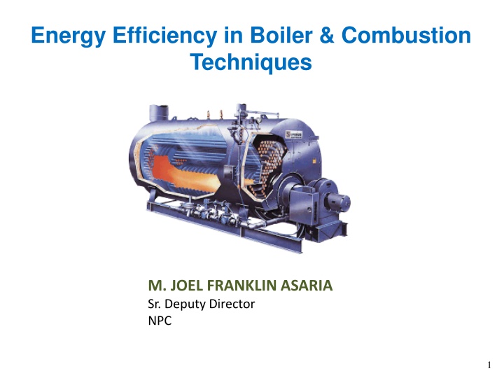
Energy Efficiency in Boiler & Combustion Techniques
This article discusses energy efficiency in boiler systems and combustion techniques, covering topics such as boiler types, classifications, specifications, and applications. It explains the process of heat generation through fuel combustion, transfer to water for steam production, and highlights various boiler types like fire tube and water tube boilers. Additionally, it explores packaged boilers, pulverized fuel boilers, and the importance of ensuring safety measures to prevent explosions. The content emphasizes the significance of assessing energy efficiency opportunities in boiler operations for improved performance and reduced environmental impact.

Download Presentation

Please find below an Image/Link to download the presentation.
The content on the website is provided AS IS for your information and personal use only. It may not be sold, licensed, or shared on other websites without obtaining consent from the author.If you encounter any issues during the download, it is possible that the publisher has removed the file from their server.
You are allowed to download the files provided on this website for personal or commercial use, subject to the condition that they are used lawfully. All files are the property of their respective owners.
The content on the website is provided AS IS for your information and personal use only. It may not be sold, licensed, or shared on other websites without obtaining consent from the author.
E N D
Presentation Transcript
Energy Efficiency in Boiler & Combustion Techniques M. JOEL FRANKLIN ASARIA Sr. Deputy Director NPC 1
OUTLINE Introduction Types & Classification Boiler System Assessment of a Boiler Combustion Energy Efficiency Opportunities 2
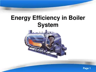
Introduction to Boiler It is an enclosed Pressure Vessel Heat generated by Combustion of Fuel is transferred to water to become steam Process: Evaporation Steam volume increases to 1,600 times from water and produces tremendous force Care explosion is must to avoid What is a boiler? 3
Boiler Specification Boiler Make & Year :XYZ & 2003 MCR(Maximum Continuous Rating) :10TPH (F & A 100oC) Rated Working Pressure :10.54 kg/cm2(g) Type of Boiler :3 Pass Fire tube Fuel Fired : Fuel Oil Heating surface : M2 4
Boiler Types and Classifications Fire in tube or Hot gas through tubes and boiler feed water in shell side Fire Tubes submerged in water Fire Tube Boiler Application Used for small steam capacities (up to 25T/ hr and 17.5kg/cm2) Merits Low Capital Cost and fuel Efficient (82%) Accepts fluctuations Steam pressure variation is less Easy to operate Packaged Boiler wide load 5
Boiler Types and Classifications Water flow through tubes Water Tubes surrounded by hot gas Water Tube Boiler Application Used for Power Plants Steam capacities range from 4.5- 120 t/ hr Characteristics High Capital Cost Used for high pressure and high capacity steam boiler Demands more controls Calls for very stringent water quality 6
Packaged Boiler Package boilers are generally of shell type with fire tube design High heat release rate in small combustion space More number of passes-so more heat transfer Large diameter tubes leading to good convective transfer. number of small heat Higher thermal efficiency 7
Pulverized Fuel Boiler Coal is pulverised to a fine powder, so that less than 2% is +300 microns, and 70-75% is below 75 microns. Coal is blown with part of the combustion air into the boiler plant through a series of burner nozzles. Combustion temperatures from 1300-1700 C Particle residence time in the boiler is typically 2-5 seconds One of the most popular system for firing pulverized coal is the tangential firing burners corner to corner to create a fire ball at the center of the furnace. takes place at using four Tangential firing 8
Fluidized bed Combustion (FBC) boiler When an evenly distributed air or gas is passed upward through a finely divided bed of solid particles such as sand supported on a fine mesh, the particles are undisturbed at low velocity. As air velocity is gradually increased, a stage is reached when the individual particles are suspended in the air stream Further, increase in velocity gives rise to bubble formation, vigorous turbulence and rapid mixing and the bed is said to be fluidized. Coal is fed continuously in to a hot air agitated refractory sand bed, the coal will burn rapidly and the bed attains a uniform temperature Fluidized Bed Combustion 9
Fluidized-bed boiler (Contd..) Advantages : Higher rates of heat transfer between combustion process and boiler tubes (thus reduced furnace area and size required), Compact design combustion temperature 850oC is lower than in a conventional furnace. The lower furnace temperatures means reduced NOx production. In addition, the limestone (CaCO3) and dolomite (MgCO3) react with SO2 to form calcium and magnesium sulfides, respectively, solids which do not escape up the stack; This means the plant can easily use high sulfur coal. Fuel Flexibility: Multi fuel firing 11
Boiler Systems Water treatment system Feed water system Steam System 1 Blow down system Fuel supply system Air Supply system Flue gas system 12
Thermic Fluid Heaters At high temperatures, steam requires a corresponding high operating pressure and establishing high temperatures with steam can be very cumbersome and expensive in some cases. In thermic fluid heaters, a special type of oil-synthetic / mineral -is used as heat carrier. This fluid can be heated up to 300oC at atmospheric pressure. In comparison steam would require a pressure of 85 bars to obtain this temperature. Advantages: High temperature operation at atmospheric pressure Optional temperature level set points No supply or treatment of hot water and hence no heat loss due to condensate flash steam No risk of corrosion Easy to operate
Assessment of a Boiler 1. BOILER PERFORMANCE Causes of poor boiler performance -Poor combustion -Heat transfer surface fouling -Poor operation and maintenance -Deteriorating fuel and water quality Heat balance: identify heat losses Boiler efficiency test: helps to determine deviation from best efficiency 13
Assessment of a Boiler HEAT BALANCE An energy flow diagram describes graphically how energy is transformed from fuel into useful energy, heat and losses Stochiometric ExcessAir Un burnt StackGas FUELINPUT STEAM OUTPUT Convection & Radiation Blow Down Ash and Un-burnt parts of Fuel inAsh 14
Assessment of a Boiler HEAT BALANCE Balancing total energy entering a boiler against the energy that leaves the boiler in different forms 12.7% Heat loss due to dry fluegas 8.1% Heat loss due to steam in fuelgas 1.7% 100.0 % Heat loss due to moisture infuel BOILER 0.3% Fuel Heat loss due to moisture inair 2.4% Heat loss due to unburnts inresidue 1.0% Heat loss due to radiation &other unaccountedloss 73.8% Heat in Steam 17
Assessment of a Boiler HEAT BALANCE Goal: improve energy efficiency by reducing avoidable losses Avoidable losses include: a. Stack gas losses (excess air, stack gas temperature) b. Losses by unburnt fuel c. Blow down losses d. Condensate losses e. Convection and radiation 18
Assessment of a Boiler BOILER EFFICIENCY Thermal efficiency: % of (heat) energy input that is effectively utilised to generate steam BOILER EFFICENCY CALCULATION 2) INDIRECT METHOD: DIRECT METHOD: The energy gain of the working fluid (water and steam) is compared with the energy content of the boiler fuel. 1) The efficiency is the different between losses and energy input 17
Assessment of a Boiler BOILER EFFICIENCY: DIRECT METHOD Boiler efficiency ( ) =Heat Output Q x (hg hf) x100 Q x GCV x 100= Heat Input hg -the enthalpy of saturated steam in kcal/kg of steam hf -the enthalpy of feed water in kcal/kg of water Parameters to be monitored: - Quantity of steam generated per hour (Q) in kg/hr - Quantity of fuel used per hour (q) in kg/hr - The working pressure (in kg/cm2(g)) and superheat temperature (oC), if any - The temperature of feed water (oC) - Type of fuel and gross calorific value of the fuel (GCV) in kcal/kg of fuel 20
Assessment of a Boiler Evaporation ratio monitoring is best suited for any boiler when its own performance is compared on day to day basis as a performance indicator; given that enthalpy gain in steam and fuel calorific value remain constant. A drop in evaporation ratio indicates a drop in Boiler efficiency. Evaporation Ratio (Steam-Fuel consumption ratio) = Feed water consumption (kg/hr) Fuel consumption (kg/hr) Type of fuel Typical Evaporation Ratio Fuel oil Solid fuel Gaseous fuel ~ 13 14 kg steam/kg fuel oil ~ 4 5 kg steam/kg solid fuel ~ 13 kg steam/Nm3 gaseous fuel 21
Assessment of a Boiler BOILER EFFICIENCY: DIRECT METHOD Advantages Quick evaluation Few parameters for computation Few monitoring instruments Easy to compare evaporation ratios with benchmark figures Disadvantages No explanation of low efficiency Various losses not calculated 22
Efficiency Calculation by Direct Method Example: Type of boiler: Coal fired Boiler Heat input data Qty of coal consumed GCV of coal :1.8 TPH :3200K.Cal/kg Heat output data Qty of steam gen Steam pr/temp Enthalpy of steam(sat) at 10 kg/cm2(g) pressure :665 KCal/kg Feed water temperature : 850 C Enthalpy of feed water : 85 KCal/kg : 8 TPH :10 kg/cm2(g)/1800C Find out the Find efficiency ? Find out the Evaporation Ratio?
Boiler efficiency (): = Q x (H h) x 100 Where Q = Quantity of steam generated per hour (kg/hr) H = Enthalpy of saturated steam (kcal/kg) h = Enthalpy of feed water (kcal/kg) (q x GCV) q = Quantity of fuel used per hour (kg/hr) GCV = Gross calorific value of the fuel (kcal/kg) Boiler efficiency ( )= 8 TPH x1000Kg/Tx (665 85) x 100 1.8 TPH x 1000Kg/T x 3200 = 80.0% Evaporation Ratio = 8 Tonne of steam/1.8 Ton of coal = 4.4
Assessment of a Boiler BOILER EFFICIENCY: INDIRECT METHOD Efficiency of boiler ( ) = 100 (i+ii+iii+iv+v+vi+vii) Principle losses: i) Loss of heat due to dry fluegas ii) Loss of heat due to evaporation of water formed due to H2infuel iii) Loss of heat due to evaporation of moisture infuel iv) Loss of heat due to moisture present in combustionair v) Loss of heat due to unburnt in flyash vi) Loss due to unburnt in bottomash vii) Loss due to radiation and other unaccountedlosses 25
Assessment of a Boiler BOILER EFFICIENCY: INDIRECT METHOD Required calculation data Ultimate analysis of fuel (H2, O2, S, C,moisture content, ashcontent) % oxygen or CO2 in the fluegas Fuel gas temperature in C(Tf) Ambient temperature in C (Ta) and humidity of airin kg/kg of dryair GCV of fuel inkcal/kg % combustible in ash (in case of solidfuels) GCV of ash in kcal/kg (in case of solidfuels) 26
Assessment of a Boiler BOILER EFFICIENCY: INDIRECT METHOD Solution : Theoretical air requirement Actual mass of air supplied/ kg of fuel (AAS) = {1 + EA/100} x theoretical air 27
Assessment of a Boiler BOILER EFFICIENCY: INDIRECT METHOD m = mass of dry flue gas in kg/kg of fuel Cp= Specific heat of flue gas (0.23 kcal/kg C) 28
Assessment of a Boiler BOILER EFFICIENCY: INDIRECT METHOD ii. Percentage heat loss due to evaporation of water formed due to H2 in fuel 29
Assessment of a Boiler BOILER EFFICIENCY: INDIRECT METHOD iii. Percentage heat loss due to evaporation of moisture present in fuel 30
Assessment of a Boiler BOILER EFFICIENCY: INDIRECT METHOD 31
Assessment of a Boiler BOILER EFFICIENCY: INDIRECT METHOD 32
Assessment of a Boiler BOILER EFFICIENCY: INDIRECT METHOD In a relatively small boiler, with a capacity of 10 MW, the radiation and unaccounted losses could amount to between 1% and 2% of the gross calorific value of the fuel while in a 500 MW boiler, values between 0.2% to 1% are typical. 33
Assessment of a Boiler BOILER EFFICIENCY: INDIRECT METHOD ADVANTAGES Complete mass and energy balance for each individual stream Makes it easier to identify options to improve boiler efficiency DISADVANTAGES Time consuming Requires lab facilities for analysis 34
Assessment of a Boiler BOILER BLOW DOWN Controls total dissolved solids (TDS) in the water that is boiled Blows off water and replaces it with feed water Conductivity measured as indication of TDS levels Calculation of quantity blow down required: Feed water TDS x % Make up water Maximum Permissible TDS in Boiler water Blow down(%) = 35
Assessment of a Boiler BOILER BLOW DOWN Two types of blow down Intermittent Manually operated valve Substantial heat loss Continuous Ensures constant TDS and steam purity Heat lost can be recovered Common in high-pressure boilers 36
Assessment of a Boiler BOILER FEED WATER TREATMENT Quality of steam depend on water treatment to control Steam purity Deposits Corrosion Efficient heat transfer only if boiler water is free from deposit-forming solids 37
Assessment of a Boiler BOILER FEED WATER TREATMENT Deposit control To avoid efficiency losses and reduced heat transfer Hardness salts of calcium and magnesium Alkaline hardness: removed by boiling Non-alkaline: difficult toremove Silica forms hard silica scales 38
Assessment of a Boiler BOILER FEED WATER TREATMENT Internal water treatment Chemicals added to boiler to prevent scale Different chemicals for different water types Conditions: Feed water is low in hardness salts Low pressure, high TDS content is tolerated Small water quantities treated Internal treatment alone not recommended 39
Assessment of a Boiler BOILER FEED WATER TREATMENT External water treatment: Removal of suspended/dissolved solids and dissolved gases Pre-treatment: sedimentation and settling First treatment stage: removal of salts Processes a) Ion exchange b) Demineralization c) De-aeration 38
Assessment of a Boiler EXTERNAL WATER TREATMENT Mechanical de-aeration Vent Spray Nozzles O2 and CO2 removed by heating feed water Boiler Feed Water Steam Scrubber Section (Trays) Economical treatment process Vacuum type can reduce O2 to 0.02 mg/l Storage Section Pressure type can reduce O2 to 0.005mg/l De-aerated Boiler Feed Water 41
Assessment of a Boiler EXTERNAL WATER TREATMENT Chemical de-aeration Removal of trace oxygen with scavenger Sodium sulphite: Reacts with oxygen: sodium sulphate Increases TDS: increased blow down Hydrazine Reacts with oxygen: nitrogen + water Does not increase TDS: used in high pressure boilers 42
Energy Efficiency Opportunities 1. 2. Stack temperature control Feed water preheating using economizers Combustion air pre-heating Incomplete combustion minimization Excess air control Avoid radiation and convection heat loss Automatic blow down control Reduction of scaling and soot losses Reduction of boiler steam pressure Variable speed control Controlling boiler loading Proper boiler scheduling Boiler replacement 3. 4. 5. 6. 7. 8. 9. 10. 11. 12. 13. 43
Energy Efficiency Opportunities 1. Stack Temperature Control Keep as low as possible If >200 C then recover waste heat 2. Feed Water Preheating Economizers Potential to recover heat from 200 300 oC flue gases leaving a modern 3-pass shell boiler 3. Combustion AirPreheating If combustion air raised by 20 C = 1% improve thermal efficiency 44
Reduce Stack Temperature Stack temperatures greater than 200 C indicates potential for recovery of waste heat. It transfer/recovery equipment and hence the urgency of taking an early shut down for water / flue side cleaning. also indicate the scaling of heat 22o C reduction in flue gas temperature increases boiler efficiency by 1%
Feed Water Preheating using Economiser For an older shell boiler, with a flue gas exit temperature of 260oC, an economizer could be used to reduce it to 200oC, Increase in overall thermal efficiency would be in the order of 3%. Condensing economizer(N.Gas) Flue gas reduction up to 65oC 6oC raise in feed water temperature, by economiser/condensate recovery, corresponds to a 1% saving in fuel consumption
Energy Efficiency Opportunities 4. Minimize Incomplete Combustion Symptoms: Smoke, high CO levels in exit flue gas Causes: Air shortage, fuel surplus, poor fuel distribution Poor mixing of fuel and air Oil-fired boiler: Improper viscosity, worn tops, cabonization on dips, deterioration of diffusers or spinner plates 47
Energy Efficiency Opportunities Combustion Control TIME All combustion requires sufficient Time which depends upon type of Reaction TEMPERATURE Temperature must be more than ignition temperature TURBULENCE Proper turbulence helps in bringing the fuel and air in intimate contact and gives them enough time to complete reaction. 48
Energy Efficiency Opportunities Combustion Reactions 49
Fouling, Scaling and Soot Fouling or scaling- Water side Act as insulators and reduces heat transfer resulting in higher flue gas temperature Higher flue gas temperatures at constant steam demand and excess air level Water treatment has to be improved-Improve softening and maintaining lower total dissolved solids (TDS) through injecting chemicals into boiler feed water and adopting proper boiler blowdown Soot- Fire side Act as insulators and reduce heat transfer resulting in higher flue gas temperature Burner is defective or air supply is insufficient. Surfaces should be cleaned of soot periodically Repair the burner and fine- tune the combustion system. water


 boiler")

")


: = Q x (H – h) x 100")