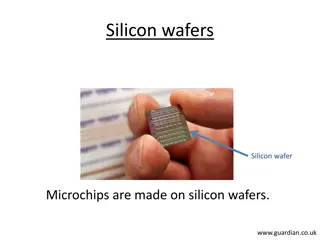
Silicon Detector Technology

Silicon Basics
Silicon is wonderful stuff
•
Low energy to create
e-hole pair (3.6 eV)
•
Long mean free path
•
High mobility (fast
charge collection)
•
Low Z (low multiple
scattering)
•
Well-developed
technology
–
Fine lithography of
structures
–
“native” oxide
R. Lipton
Silicon Basics
•
Silicon detectors are
typically high
resistivity >1 KW-cm
“float zone” silicon
•
The small energy gap
between impurity
“donor” or “acceptor”
levels means most
mobile electrons and
holes are due to
dopants (at RT)
This is why we are not
overwhelmed with
current when a bias is
applied
R. Lipton
2
Intrinsic
n-type
p-type
band
diagram
density of
states
Fermi-dirac
distribution
carrier
concentrations
Charge Drift and Collection
Diode depletion
•
Silicon detectors have lightly
doped bulk (usually n) and
heavily doped contacts.
Unusually large depleted
area.
•
Diffusion of charge carriers
will form a local depleted
region with no applied
voltage
•
As we apply external bias
the depletion region (and
the internal field) grows
until it hits the bottom.
R. Lipton
3
Very asymmetric doping in
our devices
pn junction
no external
fields
Device Characteristics
R. Lipton
4
Resistivity:
Depletion :
Electric Field:
electron, hole mobility
Effective carrier concentration
x = distance from junction D = silicon thickness
Device Testing - CV
There are a few standard tests
which measure the basic
properties of silicon detectors
•
Detectors are normally
operated fully depleted – all
impurities ionized. This leaves a
“space charge” region depleted
of charge carriers that acts like a
dielectric in the junction/ohmic
capacitor
Assume this acts as a parallel plate
capacitor (diode test structures):
R. Lipton
5
Device Testing - IV
A high quality detector will also have
low leakage current – current driven by
carrier generation in the depleted bulk.
•
Strongly temperature dependent
•
Avalanche breakdown at 3x10
5
V/cm
Measure V
bias
vs I curves
•
Look for anomalous currents
•
Breakdown voltage
Current can be affected by surface
defects, problems with the ohmic
contact, cut edge currents, impurities
(especially metals), and physical
damage
R. Lipton
6
Test structures
Rapid rise until
depletion
Charge Drift, diffusion
A ~300 micron thick piece of silicon with
initial doping concentration of 1x10
12
has V
d
of 68 V – operate at ~100 V
•
In p(n) type silicon electrons (holes)
are collected at the junction
•
As carriers drift they diffuse
•
As carriers drift they move due to
Lorentz forces from the solenoid field
•
As carriers drift electrons can
recombine with holes
•
As carriers drift they may be “eaten”
by traps in the silicon
•
Carriers in field-free regions can still
diffuse to collection electrodes
R. Lipton
7
e
= 1.5x10
-1
m
2
/Vsec
h
= 4.5 x10
-2
m
2
/Vsec
(affected by temperature,
doping concentration and the
magnitude of the applied
field)
Drift time to an electrode:
Carrier Drift and Diffusion
R. Lipton
8
Carrier Drift
R. Lipton
9
Electron, hole drift:
Drift time to an electrode:
Signal Development
•
Signal induced by moving
charges depend on
work
done by circuit.
The charge
induced on an electrode
depends on the coupling
between the moving charge
and the electrode
•
In a multi-electrode system
the
induced current on an
electrode depends on the
velocity of the charge and
the value of the effective
“
weighting
”
field
R. Lipton
10
(Radeka – from Ramo and Shockley)
Weighting field -
determined by
putting 1V on strip,
grounding all other
electrodes
Strip Detector
R. Lipton
11
(Radeka)
Signal Shapes
R. Lipton
12
Spieler
Weighting potential for a 300 μm
thick strip detector 50μm pitch
Simulation
A silicon detector is rather
complex. There are commercial
“TCAD” packages that can
simulate silicon-based devices
utilizing finite element analysis
using the detailed semiconductor
equations:
•
Internal fields
•
Coupling to electrodes
•
Charge diffusion and drift
•
Traps
•
Surface effects
R. Lipton
13
R. Lipton
14
TCAD simulation of hole
currents due to a track
impact in a n-bulk 50
micron thick pixel detector
Strip Detector
•
Bias resistor integrated on each strip
usually implanted polysilicon resistor
•
Coupling capacitor formed by very
thin (2500 A) dielectric. The
dielectric is usually a “grown
thermal” oxide supplemented with
deposited layers formed by CVD
(chemical vapor deposition)
•
In addition there are “guard rings”
which keep the field from reaching
the damaged silicon near cut edges.
•
“Microdischarge” breakdown can
occur when fields near the implant
increase due to charges in the oxide
and potential of the coupling
aluminization
R. Lipton
15
S
i
n-
p+
n+
oxide
junction
Ohmic
contact
Detector Fabrication
(Spieler)
To fabricate silicon detectors the
basic process is similar to IC
fabrication
•
Lithography utilizing masking
and exposure of photoresists
•
Growth and deposition of
silicon dioxide layers (glass)
•
Implantation or diffusion of
dopants
•
Thermal annealing to
incorporate dopants into the
silicon lattice
We deal with micron-level
features where ICs are at ~14 nm
R. Lipton
16
n, p and junctions
Silicon can be doped with donor or
acceptor impurities. This
corresponds to n (usually
phosphorus) or p (boron) type
silicon.
•
The contact between the heavily
doped and lightly doped regions
provide the junction (p-n) and ohmic (n-n
+
or p-p
+
) contacts
•
Junction contacts are high field (possible breakdown) regions
•
Ohmic contacts need to be heavily doped for a proper metal-
semiconductor contact
R. Lipton Higgs Factory
Workshop[ 11/16/2012
17
Semiconductor Surface
The surface is a crucial part of the detector
design
•
Junction side must be polished and defect-
free
•
Field must be ~0 at damaged cut edge
•
Silicon dioxide used as insulator and
passivation can accumulate charge (usually
positive)
•
An electron accumulation layer builds up
near the positively charged silicon/silicon
dioxide interface – this acts as an insulator
on a p+/n or a conductor on a n+/p junction
– need an additional “p-stop” to electrically
isolate n strips on p conductor
•
Detectors can also be sensitive to charge
attracted to the surface – affected by
humidity
R. Lipton Higgs Factory
Workshop[ 11/16/2012
18
Electron concentration
1e11 oxide charge
n-type
Detector
Layout
R. Lipton
19
bias
resistor
DC test
pad
coupling
capacitor
aluminization
Guard
ring
bond
pad
strip
implant
Bias line
100
m
Wirebonding
R. Lipton
20
Aluminum ultrasonic welding or
gold thermocompression
•
Aluminum wedge bonding
achieves the finest pitch and
does not need elevated
temperature
•
This is a bit of an art – getting
good bonds depends on machine,
operator, and especially the
surface properties of the
materials
Interconnect
How we connect the
detectors to the electronics,
cool them, and mount them
is increasingly important
•
Interconnect is a common
point of failure
•
Determines pitch
•
Can be expensive
•
Adds capacitance and
inductance
•
Can determine geometry
R. Lipton
21
Hybrid Pixel Interconnect using bump bonds
Silicon is a remarkable material with low energy requirements for creating e-hole pairs, long mean free paths, high mobility for fast charge collection, and well-developed technology for fine lithography. Silicon detectors operate based on carrier band diagrams, density of states, and Fermi-Dirac distribution, utilizing intrinsic and extrinsic properties for efficient charge drift and collection. The devices exhibit asymmetric doping, creating depletion regions crucial for their operation. Various device characteristics and testing methods, such as CV and IV tests, are used to ensure the performance and quality of silicon detectors.

Download Presentation

Please find below an Image/Link to download the presentation.
The content on the website is provided AS IS for your information and personal use only. It may not be sold, licensed, or shared on other websites without obtaining consent from the author.If you encounter any issues during the download, it is possible that the publisher has removed the file from their server.
You are allowed to download the files provided on this website for personal or commercial use, subject to the condition that they are used lawfully. All files are the property of their respective owners.
The content on the website is provided AS IS for your information and personal use only. It may not be sold, licensed, or shared on other websites without obtaining consent from the author.
E N D
Presentation Transcript
Silicon Basics Silicon is wonderful stuff Low energy to create e-hole pair (3.6 eV) Long mean free path High mobility (fast charge collection) Low Z (low multiple scattering) Well-developed technology Fine lithography of structures native oxide R. Lipton
Silicon Basics carrier band diagram density of states Fermi-dirac distribution concentrations Silicon detectors are typically high resistivity >1 KW-cm float zone silicon The small energy gap between impurity donor or acceptor levels means most mobile electrons and holes are due to dopants (at RT) This is why we are not overwhelmed with current when a bias is applied R. Lipton Intrinsic n-type p-type 2
Charge Drift and Collection Very asymmetric doping in our devices Diode depletion Silicon detectors have lightly doped bulk (usually n) and heavily doped contacts. Unusually large depleted area. Diffusion of charge carriers will form a local depleted region with no applied voltage As we apply external bias the depletion region (and the internal field) grows until it hits the bottom. R. Lipton pn junction no external fields 3
Device Characteristics V 2e qNeff 2 1 + + N D q x = = = bias eff Resistivity: ( V fd= = N N q ) Depletion : n p 2 n p V V V 2 = = x 1 electron, hole mobility fd bias fd e, h = = ) + + E x ( Electric Field: D D D Neff = = Effective carrier concentration x = distance from junction D = silicon thickness Junction side Charge density Electric Field partially depleted p+ 300 m Fully depleted n n+ Overdepleted R. Lipton 4 Ohmic side
Device Testing - CV P81_120L-002 Cv compare of P81_120L-002 & 021 P81_120L-21 1.4E+18 There are a few standard tests which measure the basic properties of silicon detectors Detectors are normally operated fully depleted all impurities ionized. This leaves a space charge region depleted of charge carriers that acts like a dielectric in the junction/ohmic capacitor Assume this acts as a parallel plate capacitor (diode test structures): 1.2E+18 1.0E+18 1/(c*c) 8.0E+17 6.0E+17 4.0E+17 2.0E+17 0.0E+00 0 50 100 150 200 250 300 350 V(v) ( qN ) 2 + N N = A D x V V d bi bias N A D ( )( qN 2 + 1 1 1 2 N N N ) = = A + D A D C A V V ( ) bi bias 2 2 N N C A qN N V V A D A D bi bias R. Lipton 5
Device Testing - IV Test structures A high quality detector will also have low leakage current current driven by carrier generation in the depleted bulk. Strongly temperature dependent Avalanche breakdown at 3x10⁵ V/cm Measure Vbias vs I curves Look for anomalous currents Breakdown voltage Current can be affected by surface defects, problems with the ohmic contact, cut edge currents, impurities (especially metals), and physical damage E kT - I(T)=T2e Rapid rise until depletion R. Lipton 6
Charge Drift, diffusion vd=mE A ~300 micron thick piece of silicon with initial doping concentration of 1x10¹² has Vd of 68 V operate at ~100 V In p(n) type silicon electrons (holes) are collected at the junction As carriers drift they diffuse As carriers drift they move due to Lorentz forces from the solenoid field As carriers drift electrons can recombine with holes As carriers drift they may be eaten by traps in the silicon Carriers in field-free regions can still diffuse to collection electrodes R. Lipton e = 1.5x10⁻¹ m2/Vsec h = 4.5 x10⁻² m2/Vsec (affected by temperature, doping concentration and the magnitude of the applied field) -x2 4Dt 1 C(x,y,t)= 4pDtde Drift time to an electrode: D ln 2 2 V V b d = = ) t x ( x d 1 V d + + V V V 2 b d 7 D
Carrier Drift and Diffusion 20 B=0, e 18 B=0, h 16 14 B=4, e 12 B=4, h 10 8 6 4 2 0 -200 -150 -100 -50 Charge Collection point 0 50 100 150 200 R. Lipton 8
Carrier Drift = = V E x ( ) Electron, hole drift: e h , e h , 2 D V V b d = = ) t x ( ln Drift time to an electrode: x d 1 V 2 d + + V V V 2 b d D 70 Charge Collection Time (Vd = 40 V) Electrons Holes 60 50 40 Time (ns) 30 20 10 0 40 50 60 70 80 90 100 Bias Voltage R. Lipton 9
(Radeka from Ramo and Shockley) Signal Development Signal induced by moving charges depend on work done by circuit. The charge induced on an electrode depends on the coupling between the moving charge and the electrode In a multi-electrode system the induced current on an electrode depends on the velocity of the charge and the value of the effective weighting field Weighting field - determined by putting 1V on strip, grounding all other electrodes R. Lipton 10
Strip Detector (Radeka) R. Lipton 11
Signal Shapes Weighting potential for a 300 m thick strip detector 50 m pitch Spieler R. Lipton 12
Simulation A silicon detector is rather complex. There are commercial TCAD packages that can simulate silicon-based devices utilizing finite element analysis using the detailed semiconductor equations: Internal fields Coupling to electrodes Charge diffusion and drift Traps Surface effects R. Lipton 13
TCAD simulation of hole currents due to a track impact in a n-bulk 50 micron thick pixel detector R. Lipton 14
bias resistor coupling capacitor (10 pf/cm) Strip Detector to readout Bias supply Bias resistor integrated on each strip usually implanted polysilicon resistor Coupling capacitor formed by very thin (2500 A) dielectric. The dielectric is usually a grown thermal oxide supplemented with deposited layers formed by CVD (chemical vapor deposition) In addition there are guard rings which keep the field from reaching the damaged silicon near cut edges. Microdischarge breakdown can occur when fields near the implant increase due to charges in the oxide and potential of the coupling aluminization Detector diode junction Ohmic contact oxide Al S i p+ Si n- n+ 2 = = E c si V break qNeff 2 R. Lipton 15
Detector Fabrication (Spieler) To fabricate silicon detectors the basic process is similar to IC fabrication Lithography utilizing masking and exposure of photoresists Growth and deposition of silicon dioxide layers (glass) Implantation or diffusion of dopants Thermal annealing to incorporate dopants into the silicon lattice We deal with micron-level features where ICs are at ~14 nm R. Lipton 16
n, p and junctions Silicon can be doped with donor or acceptor impurities. This corresponds to n (usually phosphorus) or p (boron) type silicon. The contact between the heavily doped and lightly doped regions provide the junction (p-n) and ohmic (n-n+ or p-p+) contacts Junction contacts are high field (possible breakdown) regions Ohmic contacts need to be heavily doped for a proper metal- semiconductor contact R. Lipton Higgs Factory Workshop[ 11/16/2012 17
Semiconductor Surface The surface is a crucial part of the detector design Junction side must be polished and defect- free Field must be ~0 at damaged cut edge Silicon dioxide used as insulator and passivation can accumulate charge (usually positive) An electron accumulation layer builds up near the positively charged silicon/silicon dioxide interface this acts as an insulator on a p+/n or a conductor on a n+/p junction need an additional p-stop to electrically isolate n strips on p conductor Detectors can also be sensitive to charge attracted to the surface affected by humidity R. Lipton Higgs Factory Workshop[ 11/16/2012 Electron concentration 1e11 oxide charge n-type 18
Detector Layout Bias line bias resistor Guard ring DC test pad coupling capacitor aluminization 100 m strip implant bond pad R. Lipton 19
Wirebonding Aluminum ultrasonic welding or gold thermocompression Aluminum wedge bonding achieves the finest pitch and does not need elevated temperature This is a bit of an art getting good bonds depends on machine, operator, and especially the surface properties of the materials R. Lipton 20
Interconnect Analog cable cable Analog SVX4 SVX4 How we connect the detectors to the electronics, cool them, and mount them is increasingly important Interconnect is a common point of failure Determines pitch Can be expensive Adds capacitance and inductance Can determine geometry hybrid hybrid Hybrid Pixel Interconnect using bump bonds R. Lipton 21


")