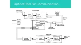
Optical Fiber Signal Degradation in Communication Engineering

Technocrats Institute of
Technology(Excellence), Bhopal
Optical Fibre Communication
Electronics & Communication
Engineering
EC-VIII
 
www.technocratsgroup.edu.in
2
Technocrats Institute of Technology(Excellence), Bhopal
<Subject Name> | <Unit-No> | <Session-
No>
Unit II
Signal degradation in Optical Fibre
Signal degradation on optical fiber due to dispersion and
attenuation, intermodal and intramodal dispersion,
Fabrication of fibers and measurement techniques like OTDR
 
www.technocratsgroup.edu.in
3
 
<Subject Name> | <Unit-No> | <Session-
No>
One of the important property of optical fiber is 
signal attenuation
. It
is also known as fiber loss or signal loss. The signal attenuation of
fiber determines the maximum distance between transmitter and
receiver. The attenuation also determines the number of repeaters
required, maintaining repeater is a costly affair.
Another important property of optical fiber is 
distortion
 mechanism.
As the signal pulse travels along the fiber length it becomes more
broader. After sufficient length the broad pulses starts overlapping with
adjacent pulses. This creates error in the receiver. Hence the distortion
limits the information carrying capacity of fiber.
Technocrats Institute of Technology(Excellence), Bhopal
 
www.technocratsgroupedu.in
4
 
<Subject Name> | <Unit-No> | <Session-
No>
Attenuation is a measure of decay of signal strength or loss of light power that
occurs as light pulses propagate through the length of the fiber.
In optical fibers the attenuation is mainly caused by two physical factors
absorption and scattering losses.
The rate at which light is absorbed is dependent on the wavelength of the light and
the characteristics of particular glass.
The attenuation of fiber is governed by the materials from which it is fabricated,
the manufacturing process and the refractive index profile chosen. Attenuation
loss is measured in dB/km.
Technocrats Institute of Technology(Excellence), Bhopal
 
www.technocratsgroup.edu.in
5
 
<Subject Name> | <Unit-No> | <Session-
No>
Technocrats Institute of
Technology(Excellence), Bhopal
 
www.technocratsgroup.edu.in
6
 
<Subject Name> | <Unit-No> | <Session-
No>
Example 1: A low loss fiber has average loss of 3 dB/km at 900 nm. Compute
the length over which –
a) Power decreases by 50 % b) Power decreases by 75 %.
=====
Solution :
 
α = 3 
dB/km
a) Power decreases by 50 %.
Technocrats Institute of
Technology(Excellence), Bhopal
 
www.technocratsgroup.edu.in
7
<Subject Name> | <Unit-No> | <Session-
No>
Technocrats Institute of Technology(Excellence), Bhopal
 
www.technocratsgroup.edu.in
8
<Subject Name> | <Unit-No> | <Session-
No>
Example 2: 
When mean optical power launched into an 8 km length of fiber is 12 μW, the
mean optical power at the fiber output is 3 μW.
Determine –
1) Overall signal attenuation in dB.
2) The overall signal attenuation for a 10 km optical link using the same fiber with splices
at 1 km intervals, each giving an attenuation of 1 dB.
Solution : Given : z = 8 km
P(0) = 120 
μ
W
P(z) = 3 
μ
W
Technocrats Institute of
Technology(Excellence), Bhopal
 
www.technocratsgroup.edu.in
9
 
<Subject Name> | <Unit-No> | <Session-
No>
Technocrats Institute of Technology(Excellence), Bhopal
 
www.technocratsgroup.edu.in
10
 
<Subject Name> | <Unit-No> | <Session-
No>
Absorption
Absorption loss is related to the material composition and fabrication
process of fiber.
Absorption is caused by three different mechanisms.
1) Absorption by atomtic defects in glass composition.
2) Extrinsic absorption by impurity atoms in glass matts.
3) Intrinsic absorption by basic constituent atom of fiber.
Technocrats Institute of Technology(Excellence), Bhopal
 
www.technocratsgroup.edu.in
11
 
<Subject Name> | <Unit-No> | <Session-
No>
Absorption by Atomic Defects
Atomic defects are imperfections in the atomic structure of the fiber
materials such as missing molecules, high density clusters of atom
groups. These absorption losses are negligible compared with intrinsic
and extrinsic losses.
The absorption effect is most significant when fiber is exposed to
ionizing radiation in nuclear reactor, medical therapies, space
missions etc.
Technocrats Institute of Technology(Excellence), Bhopal
 
www.technocratsgroup.edu.in
12
 
<Subject Name> | <Unit-No> | <Session-
No>
Extrinsic Absorption :
Extrinsic absorption occurs due to electronic transitions between the
energy level and because of charge transitions from one ion to another.
A major source of attenuation is from transition of metal impurity ions
such as iron, chromium, cobalt and copper.
Another major extrinsic loss is caused by absorption due to 
OH
(Hydroxil) ions impurities dissolved in glass.
Technocrats Institute of Technology(Excellence),
Bhopal
 
www.technocratsgroup.edu.in
13
 
<Subject Name> | <Unit-No> | <Session-
No>
Intrinsic Absorption :
Intrinsic absorption occurs when material is in absolutely pure state, no
density variation and inhomogenities. Thus intrinsic absorption sets the
fundamental lower limit on absorption for any particular material.
Intrinsic absorption results from electronic absorption bands in UV
region and from atomic vibration bands in the near infrared region.
The electronic absorption bands are associated with the band gaps of
amorphous glass materials.
In the IR (infrared) region above 1.2 μm the optical waveguide loss is
determined by presence of the OH ions and inherent IR absorption of
the constituent materials.
Technocrats Institute of Technology(Excellence),
Bhopal
 
www.technocratsgroup.edu.in
14
 
<Subject Name> | <Unit-No> | <Session-
No>
Rayleigh Scattering Losses :
Scattering losses exists in optical fibers because of microscopic
variations in the material density and composition. As glass is
composed by randomly connected network of molecules and several
oxides (e.g. SiO2, GeO2 and P2O5), these are the major cause of
compositional structure fluctuation. These two effects results to
variation in refractive index and Rayleigh type scattering of light.
Technocrats Institute of
Technology(Excellence), Bhopal
 
www.technocratsgroup.edu.in
15
 
<Subject Name> | <Unit-No> | <Session-
No>
Radiative loss: Bending Loss :
Losses due to curvature and losses caused by an abrupt change in radius of
curvature are referred to as ‘bending losses.’
The sharp bend of a fiber causes significant radiative losses and there is also
possibility of mechanical failure.
Technocrats Institute of
Technology(Excellence), Bhopal
 
www.technocratsgroup.edu.in
16
 
<Subject Name> | <Unit-No> | <Session-
No>
Microbending :
Microbending is a loss due to small bending or distortions. This small
microbending is not visible. The losses due to this are temperature related,
tensile related or crush related.
Technocrats Institute of
Technology(Excellence), Bhopal
 
www.technocratsgroup.edu.in
17
<Subject Name> | <Unit-No> | <Session-
No>
Signal Distortion in Optical Waveguide :
The pulse get distorted as it travels along the fiber lengths.
Pulse spreading in fiber is referred as 
dispersion
.
Dispersion is caused by difference in the propagation times of light rays
that takes different paths during the propagation.
The light pulses travelling down the fiber encounter dispersion effect
because of this the pulse spreads out in time domain.
Dispersion limits the information bandwidth.
Technocrats Institute of
Technology(Excellence), Bhopal
 
www.technocratsgroup.edu.in
18
<Subject Name> | <Unit-No> | <Session-
No>
Technocrats Institute of
Technology(Excellence), Bhopal
 
www.technocratsgroup.edu.in
19
 
<Subject Name> | <Unit-No> | <Session-
No>
Fig. in previous slide  shows, after travelling some distance,
pulse starts broadening and overlap with the neighbouring
pulses.
At certain distance the pulses are not even distinguishable and
error will occur at receiver. Therefore the information capacity
is specified by bandwidth-distance product (MHz . km).
 For step index bandwidth distance product is 20 MHz . km and
for graded index it is 2.5 MHz . km.
Dispersion is measured in picoseconds, nanometer per
kilometer.
 
www.technocratsgroup.edu.in
20
 
<Subject Name> | <Unit-No> | <Session-
No>
Group Delay :
Consider a fiber cable carrying optical signal equally with various
modes and each mode contains all the spectral components in the
wavelength band.
All the spectral components travel independently and they observe
different 
time delay and group delay in the direction of
propagation.
The velocity at which the energy in a pulse travels along the fiber
is known as group velocity.  
Group Velocity is given by:
 
www.technocratsgroup.edu.in
21
 
<Subject Name> | <Unit-No> | <Session-
No>
Group Delay :
Thus different frequency components in a signal will travel at
different group velocities and so will arrive at their destination at
different times, for digital modulation of carrier, this results in
dispersion of pulse, which affects the maximum rate of
modulation.
Let the difference in propagation times for two side bands is δτ.
 
www.technocratsgroup.edu.in
22
 
<Subject Name> | <Unit-No> | <Session-
No>
Material Dispersion :
Material dispersion is also called as 
chromatic dispersion
.
Material dispersion exists due to change in index of refraction for
different wavelengths.
A light ray contains components of various wavelengths centered
at wavelength λ10. The time delay is different for different
wavelength components.
This results in time dispersion of pulse at the receiving end of
fiber.
 
www.technocratsgroup.edu.in
23
 
<Subject Name> | <Unit-No> | <Session-
No>
Waveguide Dispersion :
Waveguide dispersion is caused by the difference in the index of
refraction between the core and cladding, resulting in a ‘drag’ effect
between the core and cladding portions of the power.
Waveguide dispersion is significant only in fibers carrying fewer than 5-
10 modes. Since multimode optical fibers carry hundreds of modes, they
will not have observable waveguide dispersion.
 
www.technocratsgroup.edu.in
24
 
<Subject Name> | <Unit-No> | <Session-
No>
Chromatic Dispersion :
The combination of material dispersion and waveguide dispersion is called
chromatic dispersion. These losses primarily concern the spectral width of
transmitter and choice of correct wavelength.
A graph of effective refractive index against wavelength illustrates the effects
of material, chromatic and waveguide dispersion.
 
www.technocratsgroup.edu.in
25
 
<Subject Name> | <Unit-No> | <Session-
No>
Modal Dispersion :
As only a certain number of modes can propagate down the fiber, each of
these modes carries the modulation signal and each one is incident on the
boundary at a different angle, they will each have their own individual
propagation times. The net effect is spreading of pulse, this form o
dispersion is called modal dispersion.
Modal dispersion takes place in multimode fibers. It is moderately present
in graded index fibers and almost eliminated in single mode step index
fibers.
 
www.technocratsgroup.edu.in
26
<Subject Name> | <Unit-No> | <Session-
No>
Polarization Mode Dispersion (PMD) :
Different frequency component of a pulse acquires different
polarization state (such as linear polarization and circular
polarization). This results in pulse broadening is kno
w as
polarization mode dispersion (PMD).
PMD is the limiting factor for optical communication system at high
data rates. The effects of PMD must be compensated.
 
www.technocratsgroup.edu.in
27
 
<Subject Name> | <Unit-No> | <Session-
No>
Pulse Broadening in GI Fibers :
The core refractive index varies radially in case of graded index
fibers, hence it supports multimode propagation with a low
intermodal delay distortion and high data rate over long distance
is possible.
The higher order modes travelling in outer regions of the core,
will travel faster than the lower order modes travelling in high
refractive index region. If the index profile is carefully
controlled, then the transit times of the individual modes will be
identical, so eliminating modal dispersion.
 
www.technocratsgroup.edu.in
28
 
<Subject Name> | <Unit-No> | <Session-
No>
Measurements in OFC :   Dispersion/Attenuation Measurements :
Signal attenuation is one of the most important properties of an optical
fiber because it mainly determines the maximum repeaterless separation
between transmitter and receiver.
The distortion mechanism in a fiber cause optical signal pulses to border
as they travel along a fiber. When these pulses travel sufficiently far,
they eventually overlap with neighbouring pulses creating errors in
receiver output.
For determining attenuation in fibers three major techniques are
used.
1. Cutback technique
2. Insertion loss
3. OTDR trace.
 
www.technocratsgroup.edu.in
29
 
<Subject Name> | <Unit-No> | <Session-
No>
Cutback technique :
Cutback technique is a destructive method of measuring
attenuation. It requires access to both ends of fiber
 
www.technocratsgroup.edu.in
30
 
<Subject Name> | <Unit-No> | <Session-
No>
Cutback technique :
 
www.technocratsgroup.edu.in
31
 
<Subject Name> | <Unit-No> | <Session-
No>
Measurements in OFC :   Insertion Loss :
In telecommunications, insertion loss is the loss of signal power resulting from
the insertion of a device in a transmission line or optical fiber and is usually
expressed in decibels (dB).
If an optical device is inserted into a setup, some of the optical power may be
lost in the device or at optical interfaces. Some examples:
A fiber connector, a mechanical splice or a fusion splice may be used to connect
two fibers, instead of having a single continuous fiber. Some of the optical
power will be lost due to non-perfect interfaces, not exactly matching effective
mode areas or similar factors.
The larger amount of insertion loss may be intentionally inserted in the form of
a fiber-optic attenuator.
A Faraday isolator is inserted after the output of a laser in order to prevent it
against back-reflections.
 
www.technocratsgroup.edu.in
32
<Subject Name> | <Unit-No> | <Session-
No>
Measurements in OFC :   OTDR Trace Measurements :
                                Optical Time Domain Reflectometer:
It is an instrument that is used to detect or analyze the scattered or
back reflected light through an optical fiber due to impurities and
imperfections in the fiber.
An optical time domain reflectometer is test equipment used to
evaluate the loss of signal inside an optical fiber by transmitting
laser pulses inside the fiber and measures the scattered light signal.
The 
OTDR
 consists of a high power laser transmitter that sends a
pulse of light down the 
fiber
. Back-scattered light and reflected
light returns to the 
OTDR
 through the 
fiber
 and is directed to a
sensitive receiver through a coupler in the 
OTDR
 front end
 
www.technocratsgroup.edu.in
33
 
<Subject Name> | <Unit-No> | <Session-
No>
 
www.technocratsgroup.edu.in
34
 
<Subject Name> | <Unit-No> | <Session-
No>
As we can see in the figure shown above that an optical time domain
reflectometer contains a light source (mainly a laser) and a receiver
along with a coupler or circulator. The coupler is connected with the
fiber under test through a front panel connector.
The laser produces a short and intense light beam. These pulses are
directed into the fiber link under test through a fiber optic coupler.
A coupler splits the transmitted light pulse into two halves. Due to
this, not all the transmitted pulse is directed inside fiber.
However, despite using a coupler if we use a circulator then this
wastage of transmitted signal can be avoided. As circulators are
highly directional devices that direct the overall light signal into the
fiber as well as sends the reflected or scattered light signal into the
detector.
 
www.technocratsgroup.edu.in
35
<Subject Name> | <Unit-No> | <Session-
No>
By inserting circulators in the operational unit of OTDR, the
dynamic range of the equipment can be improved. However, it also
causes the overall cost of the system to increase considerably as
circulator is highly expensive in comparison to couplers.
So, during the propagation of light pulses inside the fiber, due to
absorption and Rayleigh scattering, some losses in the transmitted
pulse occurs. Also, some losses are introduced due to splicers
connected inside the fiber or the bends inside it.
Sometimes variation in the refractive index also causes the light
energy to get reflected. This reflected energy reaches the OTDR and
in this way, it detects the characteristics of the fiber link.
 
www.technocratsgroup.edu.in
36
 
<Subject Name> | <Unit-No> | <Session-
No>
Measurements in OFC :
OTDR basically determines the characteristics of an optical fiber
cable through which optical signal propagates.
It is also used to evaluate parameters such as splice losses,
reflectance angle of a light signal, fiber attenuation etc.
When a signal is transmitted through an optical fiber cable then
during transmission some part of the signal gets reflected. This
reflection results in signal attenuation that mainly occurs due to
defects in the fiber cable.
 
www.technocratsgroup.edu.in
37
 
<Subject Name> | <Unit-No> | <Session-
No>
Measurements in OFC : 
Dispersion measurement :
An optical signal gets distorted as it travels down the fiber due to
three basic forms of dispersion, that limits the information
carrying capacity.
There are different methods to measure the dispersions effects.
Such as :
intermodal dispersion in time domain,
intermodal dispersion in frequency domain,
chromatic dispersion and
polarization mode dispersion
 
www.technocratsgroup.edu.in
38
 
<Subject Name> | <Unit-No> | <Session-
No>
Time-domain Intermodal Dispersion Measurements
Time-domain intermodal dispersion measurement involves
injecting a narrow pulse of optical energy into one end of an
optical fiber and detect the broadened output-pulse at the other
end.
 
www.technocratsgroup.edu.in
39
 
<Subject Name> | <Unit-No> | <Session-
No>
FIBER COUPLERS AND CONNECTORS:
A permanent joint of cable is referred to as 
splice and a temporary joint
can be done with the connector.
Fusion Splice,   Mechanical splice
Mechanical Misalignment:
The diameter of fiber is few micrometer hence the microscopic alignment is
required. If the radiation cone of emitting fiber does not match the
acceptance cone of receiving fiber, radiation loss takes place. The
magnitude of radiation loss depends on the degree of misalignment.
Lateral misalignment
Longitudinal misalignment
Angular misalignment
 
www.technocratsgroup.edu.in
40
 
<Subject Name> | <Unit-No> | <Session-
No>
 
www.technocratsgroup.edu.in
41
<Subject Name> | <Unit-No> | <Session-
No>
Fiber Related Losses: 
Losses in fiber cables also causes due to
differences in geometrical and fiber characteristics.
These includes,
- Variation in core diameter.
- Core area ellipticity.
- Numerical aperture.
- Refractive – index profile.
-
Core-cladding concentricity.
The user have less control over these variations since they are related to
manufacturing process.
 
www.technocratsgroup.edu.in
42
 
<Subject Name> | <Unit-No> | <Session-
No>
Fiber End – Face Preparation:
The end faces should be polished until all the scratches are removed
and they become smooth.
For 
cleaving fibers controlled fracture technique 
is
used. The process involves following
steps.
1. The fiber is scratched to create a stress concentration at the
surface.
2. Fiber is then bent over a curved form with applied tension to
produce stress
distribution.
3. Maximum stress occurs at scratch point and crack starts
propagating through fiber.
 
www.technocratsgroup.edu.in
43
 
<Subject Name> | <Unit-No> | <Session-
No>
 
www.technocratsgroup.edu.in
44
 
<Subject Name> | <Unit-No> | <Session-
No>
Fiber Related:
If the stress distribution is not properly controlled, fiber can fork
into several cracks, various types of defects can be introduced in the
fiber, few of them are mentioned here.
Defect Type:
1. Lip:   A sharp protrusion, that prevents the core from coming to
close contact.
2. Roll off:  Rounding-off of the edge of fiber.
3. Chip :     A localized fracture.
4. Hackle:  Irregularities across fiber end.
5. Mist:      Similar to hackle.
6. Step: An abrupt change in end face surface.
7. Shattering: Result of uncontrolled fracture.
 
www.technocratsgroup.edu.in
45
 
<Subject Name> | <Unit-No> | <Session-
No>
Fiber Splices:
A permanent or semipermanent connection between two individual
optical fibers is known as fiber splice. And the process of joining two
fibers is called as splicing.
Typically, a splice is used outside the buildings and connectors are
used to join the cables within the buildings. Splices offer lower
attenuation and lower back reflection than connectors and are less
expensive.
Types of Splicing: There are two main types of splicing
i) Fusion splicing.
ii) Mechanical splicing / V groove
 
www.technocratsgroup.edu.in
46
 
<Subject Name> | <Unit-No> | <Session-
No>
Fusion splicing
 is the act of joining two optical fibers end-to-end. The goal is to fuse
the two fibers together in such a way that light passing through the fibers is not
scattered or reflected back by the splice, and so that the splice and the region
surrounding it are almost as strong as the intact fiber. The source of heat used to melt
and fuse together the two glass fibers being spliced is usually an electric arc, but can
also be a laser, a gas flame, or a tungsten filament through which current is passed.
 
www.technocratsgroup.edu.in
47
 
<Subject Name> | <Unit-No> | <Session-
No>
When performing a fusion splice there are generally five different
steps:
1. Stripping the fiber
2. Cleaning the fiber: isoprophyl alcohol (IPA)
3. Cleaving the fiber
4. Fusing the fiber
5. Protecting the fiber
 
www.technocratsgroup.edu.in
48
 
<Subject Name> | <Unit-No> | <Session-
No>
 
www.technocratsgroup.edu.in
49
 
<Subject Name> | <Unit-No> | <Session-
No>
Fabrication of Optical Fibre:
 
www.technocratsgroup.edu.in
50
 
<Subject Name> | <Unit-No> | <Session-
No>
 
www.technocratsgroup.edu.in
51
 
<Subject Name> | <Unit-No> | <Session-
No>
CHEMICAL VAPOUR DEPOSITION (CVD)
OUTSIDE VAPOUR DEPOSITION (OVD)
VAPOUR AXIAL DEPOSITION (VAD)
 
www.technocratsgroup.edu.in
52
 
<Subject Name> | <Unit-No> | <Session-
No>
Modified chemical Vapour Deposition:
It is also called as Inner Vapour Phase Deposition (IVPD) since the
soot is deposited inside the target rod tube as opposed to outside
in the Outer Vapour Phase Deposition (OVPO) process.
silicon chloride, SiCl4 and germanium chloride, GeCl4 are oxidized
to form silica and germania particles.
 
www.technocratsgroup.edu.in
53
 
<Subject Name> | <Unit-No> | <Session-
No>
 
www.technocratsgroup.edu.in
54
 
<Subject Name> | <Unit-No> | <Session-
No>
Steps:
·  As in Outside Vapour Phase Deposition, Modified Chemical
Vapour Deposition also produces the preform in two steps.
·  First, reactant gases flow through a rotating glass tube made
from fused silica while a burner heats its narrow zone by travelling
back and forth along the tube. Silica and dopants form soot that is
deposited on the inner surface of the target tube.
·  A burner heats a narrow zone of this deposit and sintering
(heating without melting) occurs within this zone. The result is a
layer of sintered glass. Operating temperature is kept at around
1600℃.
 
www.technocratsgroup.edu.in
55
 
<Subject Name> | <Unit-No> | <Session-
No>
Steps:
·  The second step involves heating the soot perform to 2000℃,
thus collapsing the tube into solid glass perform.
·  The fiber that is subsequently drawn from this preform rod will
have a core that consists of the vapor-deposited material and a
cladding that consists of the original silica tube.
·  The tube is then collapsed to give a solid preform which may
then be drawn into fiber at temperatures of 2000 to 2200 °C.
·  A graded refractive index profile can be created by changing the
composition of the layers as the glass is deposited.
 
www.technocratsgroup.edu.in
56
<Subject Name> | <Unit-No> | <Session-
No>
·  This technique is the most widely used at present as it allows the
fabrication of fiber with the lowest losses.
·  Apart from the reduced OH^- impurity contamination the
MCVD process has the advantage that deposition occurs within an
enclosed reactor which ensures a very clean environment.
Slide Note
Embed
Share

Technocrats Institute of Technology (Excellence) in Bhopal delves into the concepts of signal degradation in optical fiber communication, focusing on attenuation, distortion mechanisms, and measurement techniques. The institute emphasizes the importance of signal attenuation and its impact on information carrying capacity, discussing factors such as absorption and scattering losses. Students learn about the decay of signal strength, light power loss, and methods to calculate power decrease over specific fiber lengths.

  • Optical Fiber Communication
  • Signal Degradation
  • Attenuation Loss
  • Communication Engineering

Uploaded on Apr 16, 2024 | 6 Views


Download Presentation

Please find below an Image/Link to download the presentation.

The content on the website is provided AS IS for your information and personal use only. It may not be sold, licensed, or shared on other websites without obtaining consent from the author. Download presentation by click this link. If you encounter any issues during the download, it is possible that the publisher has removed the file from their server.

E N D

Presentation Transcript


  1. Technocrats Institute of Technology(Excellence), Bhopal Optical Fibre Communication Electronics & Communication Engineering EC-VIII

  2. Technocrats Institute of Technology(Excellence), Bhopal Unit II Signal degradation in Optical Fibre Signal degradation on optical fiber due to dispersion and attenuation, intermodal and intramodal dispersion, Fabrication of fibers and measurement techniques like OTDR <Subject Name> | <Unit-No> | <Session- No> www.technocratsgroup.edu.in 2

  3. Technocrats Institute of Technology(Excellence), Bhopal One of the important property of optical fiber is signal attenuation. It is also known as fiber loss or signal loss. The signal attenuation of fiber determines the maximum distance between transmitter and receiver. The attenuation also determines the number of repeaters required, maintaining repeater is a costly affair. Another important property of optical fiber is distortion mechanism. As the signal pulse travels along the fiber length it becomes more broader. After sufficient length the broad pulses starts overlapping with adjacent pulses. This creates error in the receiver. Hence the distortion limits the information carrying capacity of fiber. <Subject Name> | <Unit-No> | <Session- No> www.technocratsgroup.edu.in 3

  4. Technocrats Institute of Technology(Excellence), Bhopal Attenuation is a measure of decay of signal strength or loss of light power that occurs as light pulses propagate through the length of the fiber. In optical fibers the attenuation is mainly caused by two physical factors absorption and scattering losses. The rate at which light is absorbed is dependent on the wavelength of the light and the characteristics of particular glass. The attenuation of fiber is governed by the materials from which it is fabricated, the manufacturing process and the refractive index profile chosen. Attenuation loss is measured in dB/km. <Subject Name> | <Unit-No> | <Session- No> www.technocratsgroupedu.in 4

  5. Technocrats Institute of Technology(Excellence), Bhopal <Subject Name> | <Unit-No> | <Session- No> www.technocratsgroup.edu.in 5

  6. Technocrats Institute of Technology(Excellence), Bhopal Example 1: A low loss fiber has average loss of 3 dB/km at 900 nm. Compute the length over which a) Power decreases by 50 % b) Power decreases by 75 %. ===== Solution : = 3 dB/km a) Power decreases by 50 %. <Subject Name> | <Unit-No> | <Session- No> www.technocratsgroup.edu.in 6

  7. Technocrats Institute of Technology(Excellence), Bhopal <Subject Name> | <Unit-No> | <Session- No> www.technocratsgroup.edu.in 7

  8. Technocrats Institute of Technology(Excellence), Bhopal Example 2: When mean optical power launched into an 8 km length of fiber is 12 W, the mean optical power at the fiber output is 3 W. Determine 1) Overall signal attenuation in dB. 2) The overall signal attenuation for a 10 km optical link using the same fiber with splices at 1 km intervals, each giving an attenuation of 1 dB. Solution : Given : z = 8 km P(0) = 120 W P(z) = 3 W <Subject Name> | <Unit-No> | <Session- No> www.technocratsgroup.edu.in 8

  9. Technocrats Institute of Technology(Excellence), Bhopal <Subject Name> | <Unit-No> | <Session- No> www.technocratsgroup.edu.in 9

  10. Technocrats Institute of Technology(Excellence), Bhopal Absorption Absorption loss is related to the material composition and fabrication process of fiber. Absorption is caused by three different mechanisms. 1) Absorption by atomtic defects in glass composition. 2) Extrinsic absorption by impurity atoms in glass matts. 3) Intrinsic absorption by basic constituent atom of fiber. <Subject Name> | <Unit-No> | <Session- No> www.technocratsgroup.edu.in 10

  11. Technocrats Institute of Technology(Excellence), Bhopal Absorption by Atomic Defects Atomic defects are imperfections in the atomic structure of the fiber materials such as missing molecules, high density clusters of atom groups. These absorption losses are negligible compared with intrinsic and extrinsic losses. The absorption effect is most significant when fiber is exposed to ionizing radiation in nuclear reactor, medical therapies, space missions etc. <Subject Name> | <Unit-No> | <Session- No> www.technocratsgroup.edu.in 11

  12. Technocrats Institute of Technology(Excellence), Bhopal Extrinsic Absorption : Extrinsic absorption occurs due to electronic transitions between the energy level and because of charge transitions from one ion to another. A major source of attenuation is from transition of metal impurity ions such as iron, chromium, cobalt and copper. Another major extrinsic loss is caused by absorption due to OH (Hydroxil) ions impurities dissolved in glass. <Subject Name> | <Unit-No> | <Session- No> www.technocratsgroup.edu.in 12

  13. Technocrats Institute of Technology(Excellence), Bhopal Intrinsic Absorption : Intrinsic absorption occurs when material is in absolutely pure state, no density variation and inhomogenities. Thus intrinsic absorption sets the fundamental lower limit on absorption for any particular material. Intrinsic absorption results from electronic absorption bands in UV region and from atomic vibration bands in the near infrared region. The electronic absorption bands are associated with the band gaps of amorphous glass materials. In the IR (infrared) region above 1.2 m the optical waveguide loss is determined by presence of the OH ions and inherent IR absorption of the constituent materials. <Subject Name> | <Unit-No> | <Session- No> www.technocratsgroup.edu.in 13

  14. Technocrats Institute of Technology(Excellence), Bhopal Rayleigh Scattering Losses : Scattering losses exists in optical fibers because of microscopic variations in the material density and composition. As glass is composed by randomly connected network of molecules and several oxides (e.g. SiO2, GeO2 and P2O5), these are the major cause of compositional structure fluctuation. These two effects results to variation in refractive index and Rayleigh type scattering of light. <Subject Name> | <Unit-No> | <Session- No> www.technocratsgroup.edu.in 14

  15. Technocrats Institute of Technology(Excellence), Bhopal Radiative loss: Bending Loss : Losses due to curvature and losses caused by an abrupt change in radius of curvature are referred to as bending losses. The sharp bend of a fiber causes significant radiative losses and there is also possibility of mechanical failure. <Subject Name> | <Unit-No> | <Session- No> www.technocratsgroup.edu.in 15

  16. Technocrats Institute of Technology(Excellence), Bhopal Microbending : Microbending is a loss due to small bending or distortions. This small microbending is not visible. The losses due to this are temperature related, tensile related or crush related. <Subject Name> | <Unit-No> | <Session- No> www.technocratsgroup.edu.in 16

  17. Technocrats Institute of Technology(Excellence), Bhopal Signal Distortion in Optical Waveguide : The pulse get distorted as it travels along the fiber lengths. Pulse spreading in fiber is referred as dispersion. Dispersion is caused by difference in the propagation times of light rays that takes different paths during the propagation. The light pulses travelling down the fiber encounter dispersion effect because of this the pulse spreads out in time domain. Dispersion limits the information bandwidth. <Subject Name> | <Unit-No> | <Session- No> www.technocratsgroup.edu.in 17

  18. Technocrats Institute of Technology(Excellence), Bhopal <Subject Name> | <Unit-No> | <Session- No> www.technocratsgroup.edu.in 18

  19. Fig. in previous slide shows, after travelling some distance, pulse starts broadening and overlap with the neighbouring pulses. At certain distance the pulses are not even distinguishable and error will occur at receiver. Therefore the information capacity is specified by bandwidth-distance product (MHz . km). For step index bandwidth distance product is 20 MHz . km and for graded index it is 2.5 MHz . km. Dispersion is measured in picoseconds, nanometer per kilometer. <Subject Name> | <Unit-No> | <Session- No> www.technocratsgroup.edu.in 19

  20. Technocrats Institute of Technology, Bhopal Group Delay : Consider a fiber cable carrying optical signal equally with various modes and each mode contains all the spectral components in the wavelength band. All the spectral components travel independently and they observe different time delay and group delay in the direction of propagation. The velocity at which the energy in a pulse travels along the fiber is known as group velocity. Group Velocity is given by: <Subject Name> | <Unit-No> | <Session- No> www.technocratsgroup.edu.in 20

  21. Group Delay : Thus different frequency components in a signal will travel at different group velocities and so will arrive at their destination at different times, for digital modulation of carrier, this results in dispersion of pulse, which affects the maximum rate of modulation. Let the difference in propagation times for two side bands is . <Subject Name> | <Unit-No> | <Session- No> www.technocratsgroup.edu.in 21

  22. Material Dispersion : Material dispersion is also called as chromatic dispersion. Material dispersion exists due to change in index of refraction for different wavelengths. A light ray contains components of various wavelengths centered at wavelength 10. The time delay is different for different wavelength components. This results in time dispersion of pulse at the receiving end of fiber. <Subject Name> | <Unit-No> | <Session- No> www.technocratsgroup.edu.in 22

  23. Waveguide Dispersion : Waveguide dispersion is caused by the difference in the index of refraction between the core and cladding, resulting in a drag effect between the core and cladding portions of the power. Waveguide dispersion is significant only in fibers carrying fewer than 5- 10 modes. Since multimode optical fibers carry hundreds of modes, they will not have observable waveguide dispersion. <Subject Name> | <Unit-No> | <Session- No> www.technocratsgroup.edu.in 23

  24. Chromatic Dispersion : The combination of material dispersion and waveguide dispersion is called chromatic dispersion. These losses primarily concern the spectral width of transmitter and choice of correct wavelength. A graph of effective refractive index against wavelength illustrates the effects of material, chromatic and waveguide dispersion. <Subject Name> | <Unit-No> | <Session- No> www.technocratsgroup.edu.in 24

  25. Technocrats Institute of Technology, Bhopal Modal Dispersion : As only a certain number of modes can propagate down the fiber, each of these modes carries the modulation signal and each one is incident on the boundary at a different angle, they will each have their own individual propagation times. The net effect is spreading of pulse, this form o dispersion is called modal dispersion. Modal dispersion takes place in multimode fibers. It is moderately present in graded index fibers and almost eliminated in single mode step index fibers. <Subject Name> | <Unit-No> | <Session- No> www.technocratsgroup.edu.in 25

  26. Technocrats Institute of Technology, Bhopal Polarization Mode Dispersion (PMD) : Different frequency component of a pulse acquires different polarization state (such as linear polarization and circular polarization). This results in pulse broadening is know as polarization mode dispersion (PMD). PMD is the limiting factor for optical communication system at high data rates. The effects of PMD must be compensated. <Subject Name> | <Unit-No> | <Session- No> www.technocratsgroup.edu.in 26

  27. Technocrats Institute of Technology, Bhopal Pulse Broadening in GI Fibers : The core refractive index varies radially in case of graded index fibers, hence it supports multimode propagation with a low intermodal delay distortion and high data rate over long distance is possible. The higher order modes travelling in outer regions of the core, will travel faster than the lower order modes travelling in high refractive index region. If the index profile is carefully controlled, then the transit times of the individual modes will be identical, so eliminating modal dispersion. <Subject Name> | <Unit-No> | <Session- No> www.technocratsgroup.edu.in 27

  28. Technocrats Institute of Technology, Bhopal Measurements in OFC : Dispersion/Attenuation Measurements : Signal attenuation is one of the most important properties of an optical fiber because it mainly determines the maximum repeaterless separation between transmitter and receiver. The distortion mechanism in a fiber cause optical signal pulses to border as they travel along a fiber. When these pulses travel sufficiently far, they eventually overlap with neighbouring pulses creating errors in receiver output. For determining attenuation in fibers three major techniques are used. 1. Cutback technique 2. Insertion loss 3. OTDR trace. <Subject Name> | <Unit-No> | <Session- No> www.technocratsgroup.edu.in 28

  29. Technocrats Institute of Technology, Bhopal Cutback technique : Cutback technique is a destructive method of measuring attenuation. It requires access to both ends of fiber <Subject Name> | <Unit-No> | <Session- No> www.technocratsgroup.edu.in 29

  30. Technocrats Institute of Technology, Bhopal Cutback technique : <Subject Name> | <Unit-No> | <Session- No> www.technocratsgroup.edu.in 30

  31. Technocrats Institute of Technology, Bhopal Measurements in OFC : Insertion Loss : In telecommunications, insertion loss is the loss of signal power resulting from the insertion of a device in a transmission line or optical fiber and is usually expressed in decibels (dB). If an optical device is inserted into a setup, some of the optical power may be lost in the device or at optical interfaces. Some examples: A fiber connector, a mechanical splice or a fusion splice may be used to connect two fibers, instead of having a single continuous fiber. Some of the optical power will be lost due to non-perfect interfaces, not exactly matching effective mode areas or similar factors. The larger amount of insertion loss may be intentionally inserted in the form of a fiber-optic attenuator. A Faraday isolator is inserted after the output of a laser in order to prevent it against back-reflections. <Subject Name> | <Unit-No> | <Session- No> www.technocratsgroup.edu.in 31

  32. Technocrats Institute of Technology, Bhopal Measurements in OFC : OTDR Trace Measurements : Optical Time Domain Reflectometer: It is an instrument that is used to detect or analyze the scattered or back reflected light through an optical fiber due to impurities and imperfections in the fiber. An optical time domain reflectometer is test equipment used to evaluate the loss of signal inside an optical fiber by transmitting laser pulses inside the fiber and measures the scattered light signal. The OTDR consists of a high power laser transmitter that sends a pulse of light down the fiber. Back-scattered light and reflected light returns to the OTDR through the fiber and is directed to a sensitive receiver through a coupler in the OTDR front end <Subject Name> | <Unit-No> | <Session- No> www.technocratsgroup.edu.in 32

  33. Technocrats Institute of Technology, Bhopal <Subject Name> | <Unit-No> | <Session- No> www.technocratsgroup.edu.in 33

  34. Technocrats Institute of Technology, Bhopal As we can see in the figure shown above that an optical time domain reflectometer contains a light source (mainly a laser) and a receiver along with a coupler or circulator. The coupler is connected with the fiber under test through a front panel connector. The laser produces a short and intense light beam. These pulses are directed into the fiber link under test through a fiber optic coupler. A coupler splits the transmitted light pulse into two halves. Due to this, not all the transmitted pulse is directed inside fiber. However, despite using a coupler if we use a circulator then this wastage of transmitted signal can be avoided. As circulators are highly directional devices that direct the overall light signal into the fiber as well as sends the reflected or scattered light signal into the detector. <Subject Name> | <Unit-No> | <Session- No> www.technocratsgroup.edu.in 34

  35. Technocrats Institute of Technology, Bhopal By inserting circulators in the operational unit of OTDR, the dynamic range of the equipment can be improved. However, it also causes the overall cost of the system to increase considerably as circulator is highly expensive in comparison to couplers. So, during the propagation of light pulses inside the fiber, due to absorption and Rayleigh scattering, some losses in the transmitted pulse occurs. Also, some losses are introduced due to splicers connected inside the fiber or the bends inside it. Sometimes variation in the refractive index also causes the light energy to get reflected. This reflected energy reaches the OTDR and in this way, it detects the characteristics of the fiber link. <Subject Name> | <Unit-No> | <Session- No> www.technocratsgroup.edu.in 35

  36. Technocrats Institute of Technology, Bhopal Measurements in OFC : OTDR basically determines the characteristics of an optical fiber cable through which optical signal propagates. It is also used to evaluate parameters such as splice losses, reflectance angle of a light signal, fiber attenuation etc. When a signal is transmitted through an optical fiber cable then during transmission some part of the signal gets reflected. This reflection results in signal attenuation that mainly occurs due to defects in the fiber cable. <Subject Name> | <Unit-No> | <Session- No> www.technocratsgroup.edu.in 36

  37. Technocrats Institute of Technology, Bhopal Measurements in OFC : Dispersion measurement : An optical signal gets distorted as it travels down the fiber due to three basic forms of dispersion, that limits the information carrying capacity. There are different methods to measure the dispersions effects. Such as : intermodal dispersion in time domain, intermodal dispersion in frequency domain, chromatic dispersion and polarization mode dispersion <Subject Name> | <Unit-No> | <Session- No> www.technocratsgroup.edu.in 37

  38. Technocrats Institute of Technology, Bhopal Time-domain Intermodal Dispersion Measurements Time-domain intermodal dispersion measurement involves injecting a narrow pulse of optical energy into one end of an optical fiber and detect the broadened output-pulse at the other end. <Subject Name> | <Unit-No> | <Session- No> www.technocratsgroup.edu.in 38

  39. Technocrats Institute of Technology, Bhopal FIBER COUPLERS AND CONNECTORS: A permanent joint of cable is referred to as splice and a temporary joint can be done with the connector. Fusion Splice, Mechanical splice Mechanical Misalignment: The diameter of fiber is few micrometer hence the microscopic alignment is required. If the radiation cone of emitting fiber does not match the acceptance cone of receiving fiber, radiation loss takes place. The magnitude of radiation loss depends on the degree of misalignment. Lateral misalignment Longitudinal misalignment Angular misalignment <Subject Name> | <Unit-No> | <Session- No> www.technocratsgroup.edu.in 39

  40. Technocrats Institute of Technology, Bhopal <Subject Name> | <Unit-No> | <Session- No> www.technocratsgroup.edu.in 40

  41. Technocrats Institute of Technology, Bhopal Fiber Related Losses: Losses in fiber cables also causes due to differences in geometrical and fiber characteristics. These includes, - Variation in core diameter. - Core area ellipticity. - Numerical aperture. - Refractive index profile. -Core-cladding concentricity. The user have less control over these variations since they are related to manufacturing process. <Subject Name> | <Unit-No> | <Session- No> www.technocratsgroup.edu.in 41

  42. Technocrats Institute of Technology, Bhopal Fiber End Face Preparation: The end faces should be polished until all the scratches are removed and they become smooth. For cleaving fibers controlled fracture technique is used. The process involves following steps. 1. The fiber is scratched to create a stress concentration at the surface. 2. Fiber is then bent over a curved form with applied tension to produce stress distribution. 3. Maximum stress occurs at scratch point and crack starts propagating through fiber. <Subject Name> | <Unit-No> | <Session- No> www.technocratsgroup.edu.in 42

  43. Technocrats Institute of Technology, Bhopal <Subject Name> | <Unit-No> | <Session- No> www.technocratsgroup.edu.in 43

  44. Technocrats Institute of Technology, Bhopal Fiber Related: If the stress distribution is not properly controlled, fiber can fork into several cracks, various types of defects can be introduced in the fiber, few of them are mentioned here. Defect Type: 1. Lip: A sharp protrusion, that prevents the core from coming to close contact. 2. Roll off: Rounding-off of the edge of fiber. 3. Chip : A localized fracture. 4. Hackle: Irregularities across fiber end. 5. Mist: Similar to hackle. 6. Step: An abrupt change in end face surface. 7. Shattering: Result of uncontrolled fracture. <Subject Name> | <Unit-No> | <Session- No> www.technocratsgroup.edu.in 44

  45. Technocrats Institute of Technology, Bhopal Fiber Splices: A permanent or semipermanent connection between two individual optical fibers is known as fiber splice. And the process of joining two fibers is called as splicing. Typically, a splice is used outside the buildings and connectors are used to join the cables within the buildings. Splices offer lower attenuation and lower back reflection than connectors and are less expensive. Types of Splicing: There are two main types of splicing i) Fusion splicing. ii) Mechanical splicing / V groove <Subject Name> | <Unit-No> | <Session- No> www.technocratsgroup.edu.in 45

  46. Technocrats Institute of Technology, Bhopal Fusion splicing is the act of joining two optical fibers end-to-end. The goal is to fuse the two fibers together in such a way that light passing through the fibers is not scattered or reflected back by the splice, and so that the splice and the region surrounding it are almost as strong as the intact fiber. The source of heat used to melt and fuse together the two glass fibers being spliced is usually an electric arc, but can also be a laser, a gas flame, or a tungsten filament through which current is passed. <Subject Name> | <Unit-No> | <Session- No> www.technocratsgroup.edu.in 46

  47. Technocrats Institute of Technology, Bhopal When performing a fusion splice there are generally five different steps: 1. Stripping the fiber 2. Cleaning the fiber: isoprophyl alcohol (IPA) 3. Cleaving the fiber 4. Fusing the fiber 5. Protecting the fiber <Subject Name> | <Unit-No> | <Session- No> www.technocratsgroup.edu.in 47

  48. Technocrats Institute of Technology, Bhopal <Subject Name> | <Unit-No> | <Session- No> www.technocratsgroup.edu.in 48

  49. Technocrats Institute of Technology, Bhopal Fabrication of Optical Fibre: <Subject Name> | <Unit-No> | <Session- No> www.technocratsgroup.edu.in 49

  50. Technocrats Institute of Technology, Bhopal <Subject Name> | <Unit-No> | <Session- No> www.technocratsgroup.edu.in 50

Related


More Related Content

giItT1WQy@!-/#giItT1WQy@!-/#giItT1WQy@!-/#giItT1WQy@!-/#giItT1WQy@!-/#giItT1WQy@!-/#giItT1WQy@!-/#