Risers and Casting Defects in Metal Casting Process
Risers are crucial in reducing shrinkage problems during casting by promoting directional solidification. Open versus blind risers have distinct characteristics affecting feeding and positioning within the mold. Rapid cooling rate and use of insulating compounds impact the efficiency of casting, while defects caused by pattern and sand casting mismatches can result in variations in thickness, fins, and crush defects. Identifying and classifying defects in casting is essential for quality control in the metal casting process.
Download Presentation

Please find below an Image/Link to download the presentation.
The content on the website is provided AS IS for your information and personal use only. It may not be sold, licensed, or shared on other websites without obtaining consent from the author.If you encounter any issues during the download, it is possible that the publisher has removed the file from their server.
You are allowed to download the files provided on this website for personal or commercial use, subject to the condition that they are used lawfully. All files are the property of their respective owners.
The content on the website is provided AS IS for your information and personal use only. It may not be sold, licensed, or shared on other websites without obtaining consent from the author.
E N D
Presentation Transcript
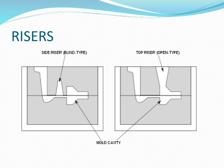
RISERS http://upload.wikimedia.org/wikipedia/commons/thumb/b/bb/Casting_riser_types.svg/400px-Casting_riser_types.svg.png
Mainly used for Reducing the shrinkage problem in the casting. Promotes direction solidification
Comparison b/w open & blind riser Open Riser Having open top Feeding force is gravity force and atm. Pressure Connected at the top/on the side at the parting line Cylindrical in shape Comparatively larger Blind Riser Closed at the top Only gravity force responsible for feeding Can be placed at any position in the mold A rounded cavity Smaller in size
Continue.. Due to rapid cooling rate insulating & exothermic compounds is recommended Height depends on height of molding box Easy to mold Slow cooling rate due to surrounding molding sand Height depend on feeding requirement Difficult to mold
Casting Defects Deviation of casting from its requirements Flaws- due to improper appearance
Classification of Defects Visually expectable Exists under surface Discovered by testing
1. DEFECTS CAUSED BY PATTERN & MOLDING BOX MISMATCH/MOLD SHIFT Mismatch of top & bottom part of the casting 1)
2) Variation in wall thickness of casting- due to oversize dimensions 3) Fins, Fash and strain- occurs at parting line. mold movement makes casting thicker 4)crush- displacement of sand during mold closing
2. DUE TO IMPROPER SAND CASTING 1) BLOWHOLES- smooth round holes visible at surface open holes May occur in cluster /one large smooth depression
Causes of blow holes Excess moisture in sand Improper baked and inadequately vented core. Presence of gas producing ingredients Extra hard ramming of sand
2) DROP mixing of sand into the molten metal Causes- i. Low green strength ii. Low mold hardness iii. Insufficient reinforcement
3) SCAB- penetration of molten metal in sand Causes- i. Too fine sand ii. High moisture content sand iii. Local heating iv. Uneven ramming
4) PIN HOLES/POROSITY- No of small holes present on casting surface Causes- High moisture in sand Metal-mold reaction
5) HOT TEARS- internal/ external cracks with ragged edges
Causes- i. ii. Low pouring temperature iii. very hard ramming iv. high dry & hot strength v. Too much shrinkage High sulphur content
6) MISRUN- Incomplete filling of casting before solidification Causes- i. Too cold metal ii. Too thin casting iii. Too small gates
7) COLD SHUTS- Inability of fusing metal coming from 2 gates
8) SLAG HOLES 9) SHRINKAGE DEFECTS
DEFECTS DUE TO MOLTEN METAL 1) SAND CUTS & WASHES- Flow of molten metal over mold /core Causes- i. Soft ramming ii. Insufficient draft iii. Improper gating system
WARPAGE HARD SPOTS SWELLS INCLUSIONS FUSION
MELTING FURNACES used to melt the metal Remelting created by combustion of fuel, electric arc, electric resistance Blast furnace for melting Electric arc furnace for remelting
SELECTION CRITERION cost Type of metal to be melted Quality required Flexibility Melting efficiency Degree of control
Furnace for melting Grey cast iron Cupola Air (reveberatory) Rotary Electric arc Steel Open hearth Electric converter
Non-ferrous metals Crucible Pot Air Rotary Induction Electric arc
CUPOLA FURNACE Melt scrap metal Economical for gray, nodular, malleable cast Fe Fuel used high grade low sulphur coke Anthracite coal Or C- briquettes
CONSTRUCTION Cylindrical shell of 6-10 mm thick plate Tuyeres dimensions- 50mm* 150mm Upto 75cm dia cupola 3-4 tuyeres used A tuyere
CONSTRUCTION Normal air pressure 12 -16 water gauge for small cupola 16 -35 for large Capacity- 1-15 tons/heat Height 2.5 m - 4 m & 6 m Inside dia- 75 cm 2.5m
CUPOLA OPERATION PREPARATION OF CUPOLA Cleaning repairing operation Patching-(2 parts ganister/silica & 1 part fireclay) Cupola block- Si - 52% -62% Al- 31%-43% Titania- 1.5%-2.5% Fluxing oxides- 3%- 6%
LIGHTNING THE FIRE Started 3 hrs before working Can be lighten by- Electric spark ignitor Gas torch
CHARGING OF CUPOLA- Adding layers of flux ,iron & coke Commonly used flux- CaCO3 Na2CO3 CaF2 CaC2 Avoid large amount of flux Amount 2% - 4% by weight of metal Fuel used Low S coke, anthracite coal & carbon briquettes
Metal fuel ratio- 4:1-12:1 Metal charge consists Pig Fe -30% Scrap iron -30% Returns -40%
MELTING soaking period- 30 min SLAGGING AND METAL TAPPING collect slag Collect metal into the ladle DROPPING DOWN THE BOTTOM Shut down the cupola
WELL Collect molten metal SUPERHEATING COMBUSTION/ OXIDIZING ZONE 15-30cm above tuyere level C, Mn, Si react with O2 Amount of heat generated- 14452 BTU/ pound Temperature 1550 -1850 degree C
REDUCING ZONE/ PROTECTIVE ZONE Temperature- 1200 degree C C + CO2 2CO - heat(2910BTU) MELTING ZONE 90cm above coke bed Temperature- 1600 degree C 3Fe +2CO Fe3C + CO2
PREHEATING ZONE Melting zone bottom of charging door Temperature about 1100 degree C STACK ZONE Exhaust Stack gases contains Nitrogen-76%, 12% CO2, CO
