Overview of Casting Alloys: Ferrous and Nonferrous Options
Commercial castings are predominantly made from alloys rather than pure metals for better properties and casting ease. Ferrous casting alloys include cast iron and steel, each with unique characteristics and challenges. On the nonferrous side, aluminum, copper alloys, and zinc alloys offer various benefits like castability, strength, and corrosion resistance, suitable for different applications. Understanding the properties and pouring temperatures of these casting alloys is crucial for successful casting processes.

Download Presentation

Please find below an Image/Link to download the presentation.
The content on the website is provided AS IS for your information and personal use only. It may not be sold, licensed, or shared on other websites without obtaining consent from the author.If you encounter any issues during the download, it is possible that the publisher has removed the file from their server.
You are allowed to download the files provided on this website for personal or commercial use, subject to the condition that they are used lawfully. All files are the property of their respective owners.
The content on the website is provided AS IS for your information and personal use only. It may not be sold, licensed, or shared on other websites without obtaining consent from the author.
E N D
Presentation Transcript
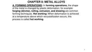
Lecture Twelve Metals for Casting Most commercial castings are made of alloys rather than pure metals Alloys are generally easier to cast, and properties of product are better Casting alloys can be classified as: Ferrous Nonferrous
Ferrous Casting Alloys: Cast Iron Most important of all casting alloys Tonnage of cast iron castings is several times that of all other metals combined Several types: (1) gray cast iron, (2) nodular iron, (3) white cast iron, (4) malleable iron, and (5) alloy cast irons Typical pouring temperatures 1400 C (2500 F), depending on composition
Ferrous Casting Alloys: Steel The mechanical properties of steel make it an attractive engineering material The capability to create complex geometries makes casting an attractive shaping process Difficulties when casting steel: Pouring temperature is high 1650 C (3000 F) At such temperatures, steel readily oxidizes, so molten metal must be isolated from air Molten steel has relatively poor fluidity
Nonferrous Casting Alloys: Aluminum Generally considered to be very castable Low pouring temperatures due to low melting temperature Pure Aluminum Tm= 660 C (1220 F) Properties: Light weight Range of strength properties by heat treatment Easy to machine
Nonferrous Casting Alloys: Copper Alloys Includes bronze, brass, and aluminum bronze Properties: Corrosion resistance Attractive appearance Good bearing qualities Limitation: high cost of copper Applications: pipe fittings, marine propeller blades, pump components, ornamental jewelry
Nonferrous Casting Alloys: Zinc Alloys Very castable, commonly used in die casting Low pouring temperatures due to low melting temperature Pure zinc Tm= 419 C (786 F) Good fluidity for ease of casting Properties: Low creep strength, so castings cannot be subjected to prolonged high stresses
Product Design Considerations Geometric simplicity Although casting can be used to produce complex part geometries, simplifying the part design usually improves castability Avoiding unnecessary complexities: Simplifies mold-making Reduces the need for cores Improves the strength of the casting
Product Design Considerations Corners on the casting Sharp corners and angles should be avoided, since they are sources of stress concentrations and may cause hot tearing and cracks Generous fillets should be designed on inside corners and sharp edges should be blended
Product Design Considerations Draft Guidelines In expendable mold casting, draft facilitates removal of pattern from mold Draft = 1 for sand casting In permanent mold casting, purpose is to aid in removal of the part from the mold Draft = 2 to 3 for permanent mold processes Similar tapers should be allowed for solid cores
Draft Design change to eliminate need for using a core: (a) original design, and (b) redesign
Product Design Considerations Dimensional Tolerances and Surface Finish Dimensional accuracy and finish vary significantly, depending on process Poor dimensional accuracies and finish for sand casting Good dimensional accuracies and finish for die casting and investment casting
Product Design Considerations Machining Allowances Almost all sand castings must be machined to achieve the required dimensions and part features Additional material, called the machining allowance, is left on the casting in those surfaces where machining is necessary Typical machining allowances for sand castings are around 1.5 and 3 mm (1/16 and 1/4 in)
Example 1 (USCS units) Caplets are used to support a sand core inside a sand mold cavity. The design of the caplets and the manner in which they are placed in the mold cavity surface allows each caplet to sustain a force of 8 lb. Several caplets are located beneath the core to support it before pouring; and several other caplets are placed above the core to resist the buoyancy force during pouring. If the volume of the core = 120 in3, and the metal is brass, determine the minimum number of caplets that should be placed (a) beneath the core, and (b) above the core. Solution: Sand density = 0.058 lb/in3. From Table 11.1, density of brass = 0.313 lb/in3. (a) Wc= 120(0.058) = 6.96 lb Although the ratio 6.96/8 is less than 1, to be safe, 2 caplets should be used beneath to support the weight of the core before pouring. Probably 3 or 4 caplets would be better to achieve stability. (b) Wm= 120(.313) = 37.56 lb Fb= 37.56 - 6.96 = 30.6 lb A minimum of 4 caplets are required above the core to resist the buoyancy force.
Example 2 (USCS units) A horizontal true centrifugal casting operation is performed to make cast iron pipe. The pipes have a length = 72.0 in, outside diameter = 6.0 in, and wall thickness = 0.375 in. (a) If the rotational speed of the pipe = 750 rev/min, determine the G-factor. (b) Is the operation likely to be successful? (c) If not, what should the rotational speed be to achieve a G-factor of 60? Solution: (a) Using outside wall of casting, R = 0.5(6)/12 = 0.25 ft v = RN/30 = (0.25)(750)/30 = 19.63 ft/sec. GF = v2/Rg = (19.63)2/(0.25 x 32.2) = 47.9 (b) Since the G-factor is less than 60, the rotational speed is not sufficient, and the operation is likely to be unsuccessful. (c) Using a G-factor = 60, N = (30/ )(2 x 32.2 x 60/(6/12))0.5= 9.55(7728)0.5= 840 rev/min
Example 3 (SI units) Horizontal true centrifugal casting is used to make aluminum rings with length = 5 cm, outside diameter = 65 cm, and inside diameter = 60 cm. (a) Determine the rotational speed that will provide a G-factor = 60. (b) Suppose that the ring were made out of steel instead of aluminum. If the rotational speed computed in part (a) were used in the steel casting operation, determine the G-factor and (c) centrifugal force per square meter (Pa) on the mold wall. (d) Would this rotational speed result in a successful operation? The density of steel = 7.87 g/cm3. Solution: (a) Use inside diameter of mold in Eq. (11.5), D = Do= 65 cm. Use g = 981 cm/s2, N = 30(2g x GF/D).5/ = 30(2 x 981 x 60/65).5/ = 406.4 rev/min (b) Rotational speed would be the same as in part (a) because mass does not enter the computation of rotational speed. N = 406.4 rev/min (c) Use 5 cm ring length as basis of area calculations. Area of this length of mold wall A = DoL = (65 cm)(5 cm) = 1021 cm2= 0.1021 m2 Volume of cast metal V = (Ro2- Ri2)(L) = ((65/2)2- (60/2)2)(5.0) = 2454.4 cm3 Density of steel = 7.87 g/cm3 Mass m = (7.87g/cm3)(2454.4 cm3) = 19,315.9 g = 19.316 kg v = RN/30 Use mean radius R = (65 + 60)/4 = 31.25 cm = 0.3125 m v = (31.25)(406.4)/30 = 1329.9 cm/s = 13.299 m/s Centrifugal force per square meter on mold wall = Fc/A where Fc= mv2/R Fc= (19.316 kg)(13.299 m/s)2/(0.3125 m) = 10,932.1 kg-m/s2 Given that 1 N = 9.81 kg-m/s2, Fc= 10,932.1/9.81 = 1114.4 N Fc/A = (1114.4 N)/(0.1021 m2) = 10,914.7 N/m2= 10,914.7 Pa (d) The G-factor of 60 would probably result in a successful casting operation.