Plastic Injection Molding for Optical Components
Plastic Injection Molding
Nachiket Kulkarni
12/08/2016
1
Introduction
Various optical technologies have plastic components
Injection molding can achieve mass production
–
Producing components with machining process may be
expensive
Economical
Plastic is an alternative to glass
–
Limited by physical properties
2
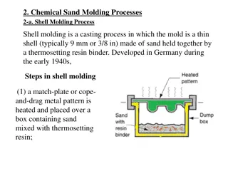
Principles of Injection Molding
3
Injection Molding Machine
–
Pellets in the hopper passed through heated barrel
–
Pellets are heated to plasticity
–
Injected into the mold and cooled
Mold Design
–
Part Model
•
The mold is initially designed on CAD
•
Optical parameters considered
Mold Design
Shrinkage
–
Plastic shrinks when it cools
–
Mold design accommodate shrinkage
–
Depends on material, temperature, etc.
Optical/ Surface Equation
–
Surfaces like freeform don’t follow correct equation
–
Shrinkage should be applied
–
Customer should apply tolerance before providing to mold maker
Optical Insert Design
–
Determines how to manufacture and polish
–
Reduces assembly, labor cost, size and weight
Split Lines
–
Cope and Drag
–
Separated by a part line
–
Needed to design runner and gating
4
Principles of Injection Molding
Mold flow
–
Flow of hot fluid must be smooth
–
Depends on wall thickness, viscosity, gating system, etc.
–
If not taken care of, removal of material is tough.
Optical Insert
–
Determined by shape, aperture, etc. of the optic
–
Adjustability feature
–
Tolerances to achieve optical alignment
Thermal Conditions
–
Factors to be considered
•
Hot runner or cold runner
•
Heat level of mold
•
Cooling by natural convection or external means, etc.
–
Thermal properties of plastic to be considered
–
CTE of metal and plastic considered
5
Principles of Injection Molding
Gates and Runners
–
Regulate the fluid flow in the cavity
–
Runner is a passageway from sprue to gate
•
Small runner under fills the cavity
•
Larger increase cooling time
–
Gates connect runner and cavity
•
Permits enough flow to fill cavity
•
Compensates shrinkage
•
Controls turbulence
Ejection
–
Pressurized transfer of polymer
•
Types
–
Pin type, sleeve type, air ejection, blade ejection
•
Dependent on the cross section
–
Sleeve type for cylindrical core, stripper plate for larger components, etc.
Venting
–
Provision for gases to escape from the cavity
–
Good venting, better the mold, less stress in the part
–
Insufficient venting causes scratches and other defects
6
General Part design
Optical mold needs both optical and mechanical
specification
Geometric Shape
–
Cavity for the part is same as mask to the face
–
Best geometric shape based on the application
–
Shrinkage and draft tolerance
Optical Surface and Control Parameter
–
Once geometry is chosen, front and back curves with their
construction points are defined
–
These points are used to design the mold
–
While fabricating in an NC machine, these construction points
are used to define the movement of the tool
7
General Part design
CAD files
–
Customer provides 3d CAD model, 2d control drawing, equations if
needed with SAG table
–
2D control drawing has optical mold requirement like engraving, callout
–
CAD design should include thermal effects, shrinkage, possible choices of
gates, ejector pin location, etc.
Optical Correction
–
Wall thickness is even
–
Optical mold, sometime doesn’t meet such requirement; manufacturing
errors
–
Cross section must be optimized
–
Avoid trapped gases and voids
Raytracing
–
Optical performance confirmed by ray trace
–
Not all optimized results are feasible to manufacture
8
Materials
Material is chosen with help of manufacturer
Design changed based on material
Commonly used
–
Polycarbonate: needs sufficient venting, hot mold
–
Polyurethane: Perfect parting line, cold mold
–
Polystyrene, acrylic, zeonex, etc.
Selection: Based on optical clarity, impact, haze,
refractive index, transmission and viscosity
Additive and Coating
–
Anti-fog, anti-scratch, antistatic, mirror, etc.
–
Ionized air to remove static charge
–
Gold coating for 98%reflection
–
Silica-Organic liquid for anti-scratch
9
Optical Mold Special Tooling
Optical geometry and special tooling design
–
Geometry determines manufacturing processes for making mold
–
If simple, turning, lapping, grinding and polishing
–
Asphere needs different set of operations
–
Freeform needs diamond turning, hand polishing
–
Designs for special tool must be done during mold design
Finishing
–
Abrasive lapping and polishing
–
Sophisticated finishing needs diamond turn
Alignment
–
Two halves must align
–
To retain alignment when injected, locking mechanism is made
10
Inspection
Steel vs Plastic
–
Determine if steel is in place
–
All components like inserts, finish inspected
–
Everything is correct means molded product might come out
perfectly
–
Inspect the part
Testing
–
Testing criteria are resolution, power, scratch/dig
–
Contact methods: CMM
–
Non Contact method: Laser scan
–
Polarisers test for stresses
–
Interferometer measure form and figure
11
References
http://info.crescentind.com/blog/bid/69598/What-is-
Insert-Molding-for-Plastic-Components
http://www.misumi-
techcentral.com/tt/en/mold/2009/07/0001-what-is-the-
molding-shrinkage-phenomenon.html
http://www.dmeuniversity.net/frmLessons.aspx?CourseID
=4&LessonID=53
https://en.wikipedia.org/wiki/Injection_mold_constructio
n#Ejection_system_types
David Borque, “Manufacturing Plastic Injection Mold”,
Novel Optical Systems Design and Optimization XI,
706117(2008)
Ulrich Greis, G. Kirchhof, Agfa-Gevaert AG, “Injection
Molding of Plastic Optics”, Optical Surface Technology,
0381(1983)
12
Plastic injection molding is a cost-effective method for mass-producing optical components, offering an economical alternative to glass. This process involves designing molds, considering factors like shrinkage and surface equations, ensuring smooth mold flow, and regulating fluid flow through gates and runners. Attention to details like mold design, thermal conditions, insert design, and ejection methods is crucial for successful plastic injection molding of optical components.

Download Presentation

Please find below an Image/Link to download the presentation.
The content on the website is provided AS IS for your information and personal use only. It may not be sold, licensed, or shared on other websites without obtaining consent from the author.If you encounter any issues during the download, it is possible that the publisher has removed the file from their server.
You are allowed to download the files provided on this website for personal or commercial use, subject to the condition that they are used lawfully. All files are the property of their respective owners.
The content on the website is provided AS IS for your information and personal use only. It may not be sold, licensed, or shared on other websites without obtaining consent from the author.
E N D
Presentation Transcript
Plastic Injection Molding Nachiket Kulkarni 12/08/2016 1
Introduction Various optical technologies have plastic components Injection molding can achieve mass production Producing components with machining process may be expensive Economical Plastic is an alternative to glass Limited by physical properties 2
Principles of Injection Molding Injection Molding Machine Pellets in the hopper passed through heated barrel Pellets are heated to plasticity Injected into the mold and cooled Mold Design Part Model The mold is initially designed on CAD Optical parameters considered 3
Mold Design Shrinkage Plastic shrinks when it cools Mold design accommodate shrinkage Depends on material, temperature, etc. Optical/ Surface Equation Surfaces like freeform don t follow correct equation Shrinkage should be applied Customer should apply tolerance before providing to mold maker Optical Insert Design Determines how to manufacture and polish Reduces assembly, labor cost, size and weight Split Lines Cope and Drag Separated by a part line Needed to design runner and gating 4
Principles of Injection Molding Mold flow Flow of hot fluid must be smooth Depends on wall thickness, viscosity, gating system, etc. If not taken care of, removal of material is tough. Optical Insert Determined by shape, aperture, etc. of the optic Adjustability feature Tolerances to achieve optical alignment Thermal Conditions Factors to be considered Hot runner or cold runner Heat level of mold Cooling by natural convection or external means, etc. Thermal properties of plastic to be considered CTE of metal and plastic considered 5
Principles of Injection Molding Gates and Runners Regulate the fluid flow in the cavity Runner is a passageway from sprue to gate Small runner under fills the cavity Larger increase cooling time Gates connect runner and cavity Permits enough flow to fill cavity Compensates shrinkage Controls turbulence Ejection Pressurized transfer of polymer Types Pin type, sleeve type, air ejection, blade ejection Dependent on the cross section Sleeve type for cylindrical core, stripper plate for larger components, etc. Venting Provision for gases to escape from the cavity Good venting, better the mold, less stress in the part Insufficient venting causes scratches and other defects 6
General Part design Optical mold needs both optical and mechanical specification Geometric Shape Cavity for the part is same as mask to the face Best geometric shape based on the application Shrinkage and draft tolerance Optical Surface and Control Parameter Once geometry is chosen, front and back curves with their construction points are defined These points are used to design the mold While fabricating in an NC machine, these construction points are used to define the movement of the tool 7
General Part design CAD files Customer provides 3d CAD model, 2d control drawing, equations if needed with SAG table 2D control drawing has optical mold requirement like engraving, callout CAD design should include thermal effects, shrinkage, possible choices of gates, ejector pin location, etc. Optical Correction Wall thickness is even Optical mold, sometime doesn t meet such requirement; manufacturing errors Cross section must be optimized Avoid trapped gases and voids Raytracing Optical performance confirmed by ray trace Not all optimized results are feasible to manufacture 8
Materials Material is chosen with help of manufacturer Design changed based on material Commonly used Polycarbonate: needs sufficient venting, hot mold Polyurethane: Perfect parting line, cold mold Polystyrene, acrylic, zeonex, etc. Selection: Based on optical clarity, impact, haze, refractive index, transmission and viscosity Additive and Coating Anti-fog, anti-scratch, antistatic, mirror, etc. Ionized air to remove static charge Gold coating for 98%reflection Silica-Organic liquid for anti-scratch 9
Optical Mold Special Tooling Optical geometry and special tooling design Geometry determines manufacturing processes for making mold If simple, turning, lapping, grinding and polishing Asphere needs different set of operations Freeform needs diamond turning, hand polishing Designs for special tool must be done during mold design Finishing Abrasive lapping and polishing Sophisticated finishing needs diamond turn Alignment Two halves must align To retain alignment when injected, locking mechanism is made 10
Inspection Steel vs Plastic Determine if steel is in place All components like inserts, finish inspected Everything is correct means molded product might come out perfectly Inspect the part Testing Testing criteria are resolution, power, scratch/dig Contact methods: CMM Non Contact method: Laser scan Polarisers test for stresses Interferometer measure form and figure 11
References http://info.crescentind.com/blog/bid/69598/What-is- Insert-Molding-for-Plastic-Components http://www.misumi- techcentral.com/tt/en/mold/2009/07/0001-what-is-the- molding-shrinkage-phenomenon.html http://www.dmeuniversity.net/frmLessons.aspx?CourseID =4&LessonID=53 https://en.wikipedia.org/wiki/Injection_mold_constructio n#Ejection_system_types David Borque, Manufacturing Plastic Injection Mold , Novel Optical Systems Design and Optimization XI, 706117(2008) Ulrich Greis, G. Kirchhof, Agfa-Gevaert AG, Injection Molding of Plastic Optics , Optical Surface Technology, 0381(1983) 12