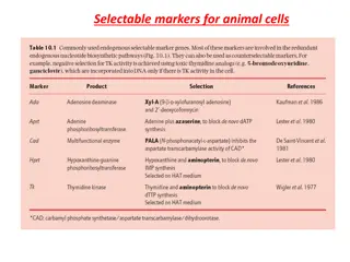
Overview of Thin Film Solar Cells and Their Evolution
Thin film solar cells are gaining popularity for their cost-effectiveness and potential for increased energy conversion efficiency. This lecture delves into the use of materials like -Si, CdTe, and CIGS, exploring their advantages and drawbacks. Additionally, it covers the evolution of thin film solar cell technology, discussing innovations such as hydrogen passivation and thick intrinsic layers for improved carrier diffusion lengths.

Download Presentation

Please find below an Image/Link to download the presentation.
The content on the website is provided AS IS for your information and personal use only. It may not be sold, licensed, or shared on other websites without obtaining consent from the author.If you encounter any issues during the download, it is possible that the publisher has removed the file from their server.
You are allowed to download the files provided on this website for personal or commercial use, subject to the condition that they are used lawfully. All files are the property of their respective owners.
The content on the website is provided AS IS for your information and personal use only. It may not be sold, licensed, or shared on other websites without obtaining consent from the author.
E N D
Presentation Transcript
Lecture-12 Thin Film Solar Cells Thin Film Solar Cells Dr. Satyanarayan Dhal
Introduction Introduction C-Si : 90% of the global PV market. How to make a PV Cost effective? Use of less material Increasing energy conversion efficiency. c-Si Wafer does not satisfy minimum material usage. This Photo by Unknown Author is licensed under CC BY
Most widely Most widely commercialized thin commercialized thin film solar cells film solar cells -Si, CdTe and CIGS All are direct band gap It enables the use of very thin material. Low temperature coefficient Can be incorporated into integrated photovoltaics (BIPV). building This Photo by Unknown Author is licensed under CC BY
Different Types Different Types The absorption coefficient of thin film materials is much lower than c-Si -Si (Less toxic) requires a lower amount of silicon. CdTe: harmful to both the producer and the consumer. -Si Uses : watches, clocks, and calculators in the late 1980s. CIGS and CdTe are more promising in terms of energy conversion efficiency than -Si. CIGS and CdTe technologies still lag behind c-Si solar cell in efficiency and reliability. This Photo by Unknown Author is licensed under CC BY-SA
Evolution of Evolution of - -Si Si Direct band gap material. Thin layer of a few micrometers Less minority carrier diffusion lengths Solution : Hydrogen passivation. The optical absorption spectrum of hydrogenated -Si: H is transparent up to 1.7 eV and is highly absorptive starting at 2 eV. Benefits of -Si: H : low manufacturing cost, and a shorter energy payback time. This Photo by Unknown Author is licensed under CC BY-SA
Evolution of Evolution of - -Si Si Thick intrinsic layer between thinner p-type and ntype layers which allows for large diffusion lengths for both minority and majority carriers. The i-layer: Thickness : 250 - 500 nm in thickness, contains small amounts of boron (0.1 1 ppm). p- and n-type doped regions are very thin. p-layer : hydrogenated amorphous-silicon carbon alloy doped with boron n-layer : phosphorus doped -Si: H or phosphorus doped microcrystalline -Si: H; Thickness : 20 30 nm. Rear contact is evaporated or sputtered aluminum. 4.8% efficiency.
Evolution of Evolution of - -Si Si 1978: Wilson used Schottky diode structure. The Schottky barrier -Si solar cell is constructed with a metal-to-N junction. Schottky barrier -Si solar cells use a thin, yet highly doped, p-type -Si, between a Schottky barrier height work function metal and the intrinsic region of -Si. This increases the Voc and Jsc of the Schottky barrier -Si solar cell . Efficiency of 6.1 %
Evolution of Evolution of - -Si Si 1986, Yamazaki et al. reported 9.3% efficiency after introducing light trapping features. 1990: Development of multi-junction cells and modules. Multiple bandgaps to allow response at multiple wavelengths. The solar spectrum : variety of photon energies, and photons with energies less than the semiconductor bandgap are often not absorbed.
Evolution of Evolution of - -Si Si Bandgaps can be readily adjusted via varied alloying. Top junction has a higher bandgap than the bottom junction. Some of the energy that would normally be lost in single junction solar cells can be captured and converted . Multijunction technologies exhibit less light- induced degradation Wiring two mechanically different -Si cells optically in series performances. Efficiency of 11.0% -Si: H solar cell. may yield higher
Evolution of Evolution of - -Si Si 1996 : Yang et al. (United Solar Systems Corporation) efficiencies of 11.8% using a spectrum splitting, triple-junction structure . This improvement in the laboratory -Si solar cell was constructed and accomplished through a dual junction and low band-gap -Si: H/ -Si: Ge alloyed cell. More efficient TCO, also known as the top conducting oxide, was created along with a p-n tunnel junction between the component cell, allowing for a better transfer of current and electric generation within the cell. 2013, Kim et al. : 13.4% stabilized efficiency in -Si: H solar cell using -Si: H in the top cell, -SiGe: H in the middle cell, and hydrogenated microcrystalline silicon( c-Si: H) in the bottom cell.
Evolution of Evolution of - -Si Si -Si: H/ c-Si: H// c-Si: H cell, and a stabilized efficiency of 13.6% was achieved. The improvement in PCE was attributed to the introduction of textured substrates with a hexagonal dimple array (also known as honeycomb-textured substrates ) into multi-junction technologies that achieved better light trapping [15]. These advances further show how the improvements of -Si: H technologies are and will be emphasized on the growth and discovery of triple junction technology, and how triple junction technologies will be exploited in the future, especially because c-Si: H possesses a higher tolerance to light soaking than pure amorphous materials [18]. The usage of multiple semiconducting materials has allowed for a broader absorption of wavelengths, thus improving the cell's power conversion
Evolution of Evolution of - -Si Si 1. -Si: H/ c-Si: H// c-Si: H cell, : efficiency of 13.6% . 2. Textured substrates with a hexagonal dimple array ( honeycomb-textured substrates ) into multi- junction technologies; achieved better light trapping. 3. c-Si: H possesses a higher tolerance to light soaking than pure amorphous materials. 4. The usage of multiple semiconducting materials has allowed for a broader absorption of wavelengths, thus improving the cell's power conversion efficiency.
Evolution of Evolution of - -Si Si c-Si: H : a higher tolerance to light soaking than pure amorphous materials .
Evolution of Evolution of - -Si Si -Si solar cell still dominates the consumer electronics industry, Why , terrestrial applications with them are not economical ? Very low efficiency and instability Systems cost : much higher than the cost of purchasing the solar cells. This is the major reason the commercial activities of the -Si technology are almost extinct. Better Efficient :CIGS technologies show potential if issues regarding materials availability are absolved, and recombination losses are reduced. This Photo by Unknown Author is licensed under CC BY-SA
References References Lee, T.D., Renewable and Sustainable Energy Reviews (2016), http://dx.doi.org/10.1016/j.rser.2016.12.028 [1] Chopra KL, Paulson PD, Dutta V. Thin film solar cells: an overview [12.2 3]. Prog Photovolt: Res Appl 2004:69 92. [2] Takahashi Kiyoshi, Konagai Makoto. Amorphous silicon solar cells; 1986. [3] Shah Arvind, et al. Photovoltaic technology: the case for thin-film solar cells. science 1999;285.5428:692 8. [4] Carlson DE, Wronski CR. Amorphous silicon solar cell. Appl Phys Lett 1976;28:671 3. [5] Carlson DE, Wronski CR. Solar cells using discharge produced amorphous silicon. J Electron Mater 1977;6(2):95 106. [6] Wilson JIB, McGill J. Amorphous-silicon mis solar cells [2.3.1]. IEE J Solid-State Electron Devices 1978:S7 S10. [7] Carlson DE. Recent developments in amorphous silicon solar cells. Sol EnergyMater 1980;3.4:503 18. [8] Tawada Yoshihisa, et al. Hydrogenated amorphous silicon carbide as a window material for high efficiency -Si solar cells. Sol Energy Mater 1982;6(3):299 315. [9] Tawada Y, et al. Properties and structure of -SiC: H for high efficiencya Si solar cell. J Appl Phys 1982;53(7):5273 81. [10] Yamazaki S. et al., Fabrication of the Large-Area Integrated -Si Solar Cells. In: MRS proceedings. Vol. 70. Cambridge University Press; 1986. [11] Guha S, Yang J, Banerjee A, Glatfelter T, Xu X. Advances in amorphous silicon alloy based multijunction cells and modules. In: AIP conference proceedings. Vol.268(64); 1992. [12] Yang J, Xu X, Banerjee A, Guha S. Proceedings 25th IEEE PVSC. Vol. 1041; 1996. [13] Yang J, et al. Triple-junction amorphous silicon alloy solar cell with 14.6% initialand 13.0% stable conversion efficiencies. Appl Phys Lett 1997;70(2975):2975 7. [14] Soohyun Kim , et al. Remarkable progress in thin-film silicon solar cells usinghigh-efficiency triple-junction technology. Sol Energy Mater Sol Cells 2013;119:26 35. [15] Sai Hitoshi, et al. Triple-junction thin-film silicon solar cell fabricated onperiodically textured substrate with a stabilized efficiency of 13.6%. Appl Phys Lett 2015;106(21):213902.