Introduction to Convolutional Codes and Encoders
Convolutional codes are a type of error-correcting code that groups data digits into smaller blocks and encodes them with linear finite state shift registers. These codes are defined by generators and can be visualized using tree diagrams, state diagrams, and trellis diagrams. Learn about the structure, encoding process, generators, and methods to describe convolutional codes.

Download Presentation

Please find below an Image/Link to download the presentation.
The content on the website is provided AS IS for your information and personal use only. It may not be sold, licensed, or shared on other websites without obtaining consent from the author.If you encounter any issues during the download, it is possible that the publisher has removed the file from their server.
You are allowed to download the files provided on this website for personal or commercial use, subject to the condition that they are used lawfully. All files are the property of their respective owners.
The content on the website is provided AS IS for your information and personal use only. It may not be sold, licensed, or shared on other websites without obtaining consent from the author.
E N D
Presentation Transcript
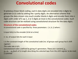
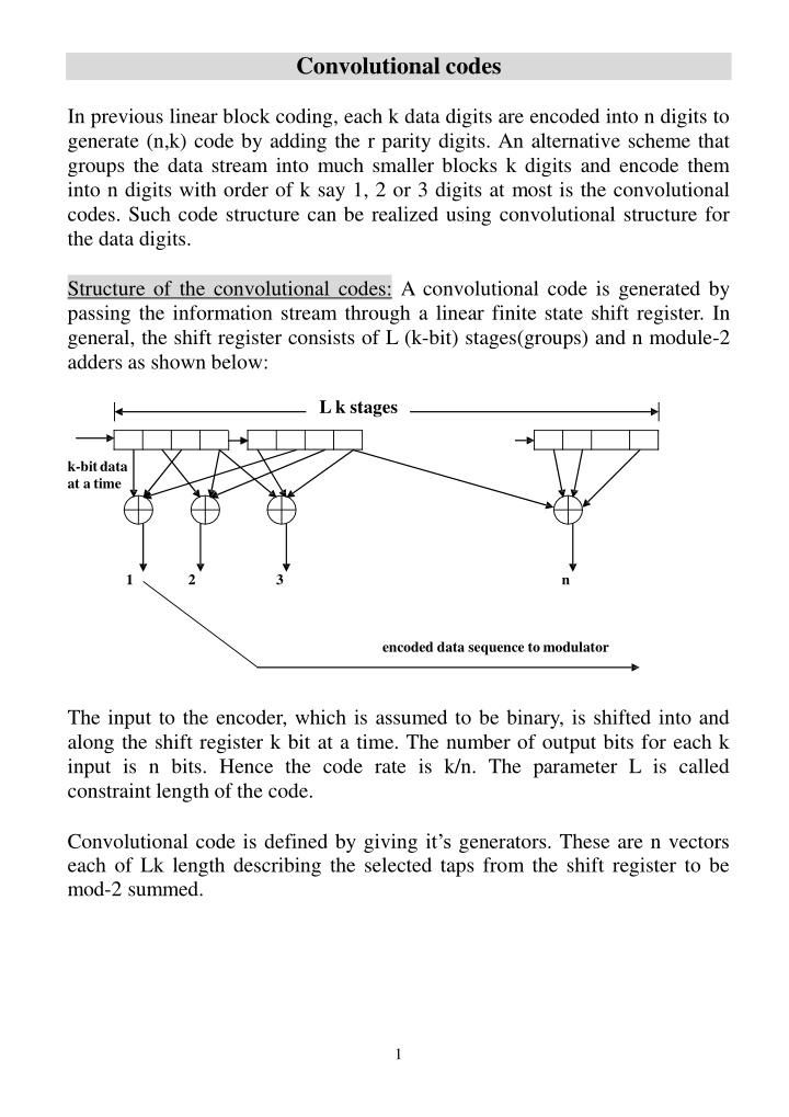
Convolutional codes In previous linear block coding, each k data digits are encoded into n digits to generate (n,k) code by adding the r parity digits. An alternative scheme that groups the data stream into much smaller blocks k digits and encode them into n digits with order of k say 1, 2 or 3 digits at most is the convolutional codes. Such code structure can be realized using convolutional structure for the data digits. Structure of the convolutional codes: A convolutional code is generated by passing the information stream through a linear finite state shift register. In general, the shift register consists of L (k-bit) stages(groups) and n module-2 adders as shown below: L k stages k-bitdata at a time 1 2 3 n encoded data sequence to modulator The input to the encoder, which is assumed to be binary, is shifted into and along the shift register k bit at a time. The number of output bits for each k input is n bits. Hence the code rate is k/n. The parameter L is called constraint length of the code. Convolutional code is defined by giving it s generators. These are n vectors each of Lk length describing the selected taps from the shift register to be mod-2 summed. 1
Example1: Consider the convolutional encoder with L=3, k=1, n=3 shown below: C1 Q1 Q2 Q3 Input C2 output C3 Initially, the shift register is assumed to be loaded with 0 s. Here, the 3 vectors generators are: [g1]=[100], [g2]=[101], [g3]=[111] describing the connections for C1,C2 and C3 output (in octal form, these generators are given as 4, 5, 7). Suppose the 1st. input bit is a 1, then the outputs C1C2C3 will be 111. If the 2nd.bit is a 0, the output will be 001 and so on. Example2: Consider the 2/3 rate convolutional encoder with generators [g1]=[1011], [g2]=[1101], [g3]=[1010](in octal these generators are 13,15,12). This is shown below: Q1 Q2 Q4 Q3 C1 Input 2bits C2 output C3 There are 3 methods that are used to describe a convolutional code. These are tree diagram, state diagram and trellis diagram. Tree diagram: To draw the tree diagram of the coder described in example1. Here, we make a simple tree structure starting with Q1Q2Q3=[000], at each node of the tree there are two branches one for 0 input & the other for 1 input between ( ) brackets. 2
Q1Q2Q3=000 (1)111 (0)000 Q1Q2Q3=100 Q1Q2Q3=000 (1)110 (0)001 (1)111 (0)000 Q1Q2Q3=110 Q1Q2Q3=010 Q1Q2Q3=100 Q1Q2Q3=000 (1)101 (0)010 (1)100 (0)011 (1)110 (0)001 (1)111 (0)000 Q1Q2Q3=111 Q1Q2Q3=011 1Q2Q3=101 Q1Q2Q3=001 Q1Q2Q3=110 Q1Q2Q3=010 Q1Q2Q3=100 Q1Q2Q3=000 starting with Q1Q2Q3=000, then if the input is 1 then shift register state becomes 100 and this will give 111 output (shown adjacent to the input bit in brackets) according to the connections of C1 C2 C3. However, if the input is 0 then the state is not changed giving 000 output. So 1st. level of branching occurs due to the 1st. data bit. For the 2nd. data bit, and assuming that the 1st. bit was 0, then the same two branches will be repeated. But if the 2nd. bit is a 1 and the 1st. bit was a 1 also, then the new state will be 110 giving 110 output. But if the 2nddata bit was a 0 and the 1st. bit was a 1 then the new state will be 010 giving 001 output. So the 2ndlevel of branching occurs due to the 2nddata bit and so on, the 3rddata bit will give the 3rdlevel of branching. Also, if we draw the 4thlevel due to the 4thdata bit, then we will notice that the same tree structure will be repeated. Notes: 1at each node, the output C1C2C3 is determined by the input bit and the four possible states of Q2Q3. 2 Above tree is not suitable in some cases, in stead we redraw it as shown below. Note that only output bits are shown at each node. Upward branching is for 0 input and downward branching for 1 input. Also, the new state of Q2Q3 is given as letters a,b,c,d that stand for Q2Q3=00,01,10,11 respectively. Note that the tree starts to repeat at the 4th data input.This tree can be used to find the output sequence for a given data. . 3
The state of the first (L-1)k stages of the shift register: b=01; a=00; d=11 c=10; If say the data input is 1011 , then the output sequence will be: 111 001 100 110 .. which is a certain path traced on this tree Example2: Draw the tree diagram of the convolutional encoder given in example2. (hint: note that here there are 4 branches at each node corresponding to the four possible inputs 00, 01, 10, 11 . Also the output sequence is determined by the two data input and the states of Q3Q4). 4
L=2, k=2, n=3 convolutional encoder g1 = =(1011) g2 = =(1101) g3 = =(1010) The state of the first (L-1)k stages of the shift register: b=01; a=00; d=11 c=10; If the input bits 1011 Then the output bits 111000 State diagram: An alternative picture to the convolutional encoder is to draw the state diagram of the encoder as a finite state machine. Given the convolutional encoder having constraint length L (L groups) each has k bit. This encoder has 2k(L-1) states depending on the content of the last 5
L-1 groups. Also this encoder has 2kbranches leaving each state and 2k branches entering into each state. To draw the state diagram, a simple state transition table is prepared first according to the generator vectors and the values of L&k. Example1: Draw the state diagram of the convolutional encoder given in example1. Here L=3, k=1, [g1]=[100],[g2]=[101],[g3]=[111]. Hence, there are 22=4 states which are the same states a,b,c,d already defined when we explained the tree diagram. Also there are 21=2 branches leaving from or entering into each node( state). First, we will prepare the transition table that gives the present state of Q2Q3, next state of Q2Q3 and the output for each possible two inputs: Input 0 1 0 1 0 1 0 1 Note that the outputs C1C2C3 are calculated according to g1,g2, g3 from the input as being Q1 together with Q2 &Q3. Once we obtain this table, it is now so easy to draw the state diagram, where we mark the states of a,b,c,d according to the content of Q2Q3. present state of Q2Q3 00(a) 00(a) 01(b) 01(b) 10(c) 10(c) 11(d) 11(d) next state of Q2Q3 00(a) 10(c) 00(a) 10(c) 01(b) 11(d) 01(b) 11(d) output C1C2C3 000 111 011 100 001 110 010 101 (0)000 a (1)111 (0)011 (1)111 (0) 010 d b (1)110 (1)100 (0)001 c For each branch, data input is shown between brackets and output sequence is followed. Also note that, from this state diagram we can directly find the 6
output sequence for the data for a given input if the initial state is given( if it is not given, zero state (state a) is assumed). For example, for data sequence 1011 . The output will be: 111 001 100 110 Example2: Draw the state diagram of the encoder of example2. here there are 4 branches at each node corresponding to the four possible inputs 00, 01, 10, 11 . Also the output sequence is determined by the two data input and the states of Q3Q4. After preparing the transition table, we draw the state diagram Initialstate 7
Trellis diagram: This is a very important diagram for the convolutional encoder since the very powerful decoder depends on this diagram. This diagram is directly obtained from the same transition table already obtained when we draw the state diagram. The only difference is that transitions between states are given as levels between the possible states. To explain, we draw the trellis diagram of the encoder given in example1. Example: Draw the trellis diagram of the encoder of example1. For convenience, we re-tabulate the same transition table: Input present state of Q2Q3 next state of Q2Q3 0 00(a) 1 00(a) 0 01(b) 1 01(b) 0 10(c) 1 10(c) 0 11(d) 1 11(d) output C1C2C3 00(a) 10(c) 00(a) 10(c) 01(b) 11(d) 01(b) 11(d) 000 111 011 100 001 110 010 101 1st databit 2nd databit 4th databit 5th databit 3rd databit 8
Notes: 1- The trellis diagram at the 3rdand above data input is repeated having repeated branching.And in general up to constraint length L. 2-we can read data directly from the trellis diagram, for example for the data bits 1011 , the output will be 111 001 100 110 .. which represents a certain path on the trellis diagram. Example2 : Draw the trellis diagram of the encoder of example2. L=2, k=2, n=3 convolutional code Initial state i = = i = =1 i = = 2 i = = 3 Input bit: 10 1100 Output bits: 111 000011 9
Decoding of convolutional codes(ViterbiAlgorithm): Unlike a block code which has a fixed length n, a convolutional code has no well-defined block size. Of course, a convolutional code can be truncated periodically, thus forcing it to have a fixed length. When this is done, a number of 0 bits are appended to the last information bit to clear the shift register. Since these appended 0 s carry no information, then the efficiency is reduced. In order to keep the efficiency as close as to the code rate, a convolutional code is truncated periodically with period of several times the constraint length L. These are called frames. Viterbi algorithm: This is the same as maximum likelihood criterion since it depends on choosing the correct decoded data corresponding to minimum Hamming distance, for each frame. This algorithm is best explained with the help of the trellis diagram. Let us recall the encoder of example1. Choosing frame length of 2 times L( say), then the data input sequence to encoder is 10110100 where the last 2 bits are appended 0 s(at most as much as L-1 since if the encoder was at any state, two successive 0 s will bring the encoder back to state a ).This data input will give transmitted output : 111 001 100 110 010 100 001 011 .. Assuming that the received sequence is : 111 101 100 010 010 101 001 011 with three underlined erroneous bits. Let us redraw the trellis of this encoder once again. 11
Received sequence: 111 101 100 010 010 101 001 011 1stdata 2nddata bit 3rddata bit 4thdata 5thdata 6thdata 7thdata 8thdata bit bit bit bit bit bit Assuming zero initial state(state a) , then we find the Hamming distance between the 1st3 bits received( corresponding to one data bit) and the two output bit sequences merging from state a (000 & 111), these are 3 and 0 numbers marked on these lines. Next, we proceed to the 2nd. 3- bit received. These will give Hamming distances of 2 &1 for branches of state a and 1 & 2 for branches of state c. we then find the total Hamming distance for the first two data bits at each node, these are [5],[1],[4],&[2]. Of course, if these two data bits are the only bits received, then we decide on state b since it has the lowest Hamming distance. But, if we proceed to the 3rddata bit then the Hamming distances for the two branches of each state will be 1&2 for state a, 3&0 for state b, 2&1 for state c and 2&1 for state d.If we sum total Hamming distance at the end of the 3rddata bit, then we will have two paths entering into each node. Here, we select only one of these paths having the lowest Hamming distance. This path is called the survivor. These survivors are branches not crossed with . Proceed to the 4thdata bit we will get a total Hamming distance of [5],[3],[6],[2] at nodes a,b,c &d respectively after 11
discarding other branches and keeping only the survivors at each node. If we proceed until the last data bit we will obtain a total Hamming distances of [3],[7],[6] &[8]. Of course, this is expected since we made three errors. The path leading to the last node having minimum Hamming distance is selected. This path is labeled bold giving the actual transmitted sequence 111 001 100 110 010 100 001 011 .And this gives the actual data bits 10110100 The worked out example for Viterbi decoding procedure succeeds in correcting the three chosen errors. However, if more errors are added, the decoder will reach to more than one optimum solutions ( more than one paths having the same minimum of total Hamming distance from the 1stdata bit up to the last data bits. For convolutional codes to correct more errors, then this can be done either 1- by increasing L and hence increasing the memory locations required to store all distances for the increased number of states. Or 2-by increasing n for the same k i.e. reducing the rate. Usually tables give the generators ( in octal form) for different values of L and rates k/n. Homework: Draw the trellis diagram of the convolutional encoder having L=3,k=1, with generators [g1]=[101], [g2]=[111], [g3]=[111]. Use this diagram and repeat Viterbi decoding procedure with 3 & 4 random errors in 8 data bits (i.e. in 24 bits received sequences). 12


k")


:")