Interrupts and Memory Organization
Concept of interrupts and memory organization in microcontrollers, including interrupt sources, interrupt handling procedures, and memory storage techniques. Learn about interrupt registers, interrupt sources at RB0, and EEPROM memory management.

Download Presentation

Please find below an Image/Link to download the presentation.
The content on the website is provided AS IS for your information and personal use only. It may not be sold, licensed, or shared on other websites without obtaining consent from the author.If you encounter any issues during the download, it is possible that the publisher has removed the file from their server.
You are allowed to download the files provided on this website for personal or commercial use, subject to the condition that they are used lawfully. All files are the property of their respective owners.
The content on the website is provided AS IS for your information and personal use only. It may not be sold, licensed, or shared on other websites without obtaining consent from the author.
E N D
Presentation Transcript
PREKIDI (INTERAPTI)
Prekidi Loop Delay500 Label end bsf call bcf call goto PORTB, 7 Delay500 PORTB, 7 Delay500 Loop clrf clrf movlw movwf delayL delayM d'3' delayH decfsz goto decfsz goto decfsz goto return delayL Label delayM Label delayH Label
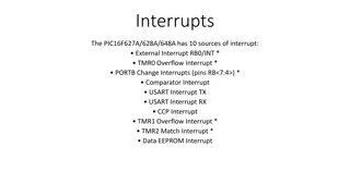
Izvori prekida Promena logi kog stanja na no ici RB0 Prekora enje slobodnog broja a TMR0 Zavr etak ciklusa upisa u EEPROM Promena na jednoj od no ica RB4- RB7
OPTION REGISTAR bit 7: RBPU: PORTB Pull-up Enable bit 0 = PORTB pull-ups are disabled 1 = PORTB pull-ups are enabled (by individual port latch values). bit 6 INTEDG: Interrupt Edge Select bit 1 = Interrupt on rising edge of RB0/INT pin 0 = Interrupt on falling edge of RB0/INT pin
Prekid na RB0 PROCESSOR 16F84 #include "p16f84.inc" __CONFIG _XT_OSC & _PWRTE_ON & _WDT_OFF & _CP_OFF org 0x00 goto main org 0x04 goto ISR main bsf STATUS, RP0 movlw b'00000001' movwf TRISB bcf OPTION_REG, INTEDG bsf OPTION_REG, NOT_RBPU bcf STATUS, RP0 clrf PORTB bsf PORTB, 7 bsf INTCON, INTE bsf INTCON, GIE
Prekid na RB0 Loop goto Loop ISR bcf INTCON, INTF btfss PORTB,7 goto Lab1 bcf PORTB,7 retfie Lab1 bsf PORTB,7 retfie end
EEPROM MEMORIJA bit 3WRERR (EEPROM Error Flag bit) Error during writing to EEPROM 1=error occured 0=error did not occur bit 0 RD (Read Control bit) 1=initializes reading 0=does not initialize reading bit 1WR (Write Control bit) 1=initializes writing 0=does not initialize writing bit 4EEIF (EEPROM Write Operation Interrupt Flag bit) Bit used to inform that writing data to EEPROM has ended. 1=writing terminated 0=writing not terminated yet, or has not started bit 2WREN (EEPROM Write Enable bit) Enables writing to EEPROM 1=writing allowed 0=writing disallowed
EEPROM MEMORIJA EEPROM read
EEPROM MEMORIJA EEPROM write