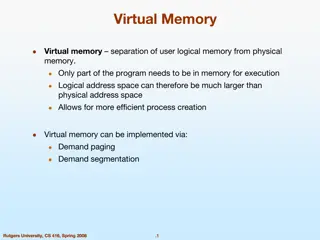
Memory Allocation in Operating Systems

Fair Physical Memory Allocation

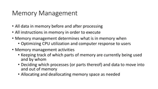
The memory management subsystem
allows each running process in the
system a fair share of the physical
memory of the system.
Shared Virtual Memory
Although virtual memory allows
processes to have separate (virtual)
address spaces, there are times when
you need processes to share memory.
For example there could be several
processes in the system running the
bash command shell. Rather than have
several copies of bash, one in each
process's virtual address space, it is
better to have only one copy in
physical memory and all of the
processes running bash share it.
Dynamic libraries are another common
example of executing code shared
between several processes.
Shared memory can also be used as an
Inter Process Communication (IPC)
mechanism, with two or more
processes exchanging information via
memory common to all of them. Linux
supports the Unix System V shared
memory IPC.
•
3.1 An Abstract Model of Virtual Memory
Figure 3.1: Abstract model of Virtual
to Physical address mapping
Before considering the methods that
Linux uses to support virtual memory
it is useful to consider an abstract
model that is not cluttered by too much
detail.
As the processor executes a program it
reads an instruction from memory and
decodes it. In decoding the instruction
it may need to fetch or store the
contents of a location in memory. The
processor then executes the instruction
and moves onto the next instruction in
the program. In this way the processor
is always accessing memory either to
fetch instructions or to fetch and store
data.
In a virtual memory system all of these
addresses are virtual addresses and not
physical addresses. These virtual
addresses are converted into physical
addresses by the processor based on
information held in a set of tables
maintained by the operating system.
To make this translation easier, virtual
and physical memory are divided into
handy sized chunks called
pages.
These pages are all the same size, they
need not be but if they were not, the
system would be very hard to
administer. Linux on Alpha
AXP systems uses 8 Kbyte pages and
on Intel x86 systems it uses 4 Kbyte
pages. Each of these pages is given a
unique number; the page frame
number (PFN).
In this paged model, a virtual address
is composed of two parts; an offset and
a virtual page frame number. If the
page size is 4 Kbytes, bits 11:0 of the
virtual address contain the offset and
bits 12 and above are the virtual page
frame number. Each time the processor
encounters a virtual address it must
extract the offset and the virtual page
frame number. The processor must
translate the virtual page frame number
into a physical one and then access the
location at the correct offset into that
physical page. To do this the processor
uses
page tables.
Interrupts And Exceptions
An
interrupt is usually defined as an
event that alters the sequence of
instructions executed by a processor.
Such events correspond to electrical
signals generated by hardware circuits
both inside and outside of the CPU
chip.
Interrupts are often divided into
synchronous and asynchronous
interrupts:
Synchronous interrupts are produced
by the CPU control unit while
executing
instructions and are called synchronous
because the control unit issues them
only after terminating the execution of
an instruction.
Asynchronous interrupts are
generated by other hardware devices
at arbitrary times with respect to the
CPU clock signals. Intel 80x86
microprocessor manuals designate
synchronous and asynchronous
interrupts as exceptions and interrupts,
respectively. We'll adopt this
classification, although we'll
occasionally use the term "interrupt
signal" to designate both types together
(synchronous as well as
asynchronous). Interrupts are issued by
interval timers and I/O devices; for
instance, the arrival of a keystroke
from a user sets off an interrupt.
Exceptions, on the other hand, are
caused either by programming errors
or by anomalous conditions that must
be handled by the kernel. In the first
case, the kernel handles the exception
by delivering to the current process one
of the signals familiar to every Unix
programmer. In the second case, the
kernel performs all the
steps needed to recover from the
anomalous condition, such as a page
fault or a request (via an int
instruction) for a kernel service.
The Role of Interrupt Signals
As the name suggests, interrupt signals
provide a way to divert the processor
to code outside the normal flow of
control. When an interrupt signal
arrives, the CPU must stop what it's
currently doing and switch to a new
activity; it does this by saving the
current value of the program counter
(i.e., the content of the eip and cs
registers) in the Kernel Mode stack and
by placing an address related to the
interrupt type into the program counter.
There is a key difference between
interrupt handling and process
switching: the code executed by an
interrupt or by an exception handler is
not a process. Rather, it is a kernel
control path that runs on behalf of the
same process that was running when
the interrupt occurred. As a kernel
control path, the interrupt handler is
lighter than a process (it has less
context and requires less time to set up
or tear down).
Interrupt handling is one of the most
sensitive tasks performed by the
kernel, since it must satisfy the
following constraints:
Interrupts can come at any time, when
the kernel may want to finish
something else it was trying to do. The
kernel's goal is therefore to get the
interrupt out of the way as soon as
possible and defer as much processing
as it can. For instance, suppose a block
of data has arrived on a network line.
When the hardware interrupts the
kernel, it could simply mark the
presence of data, give the processor
back to whatever was running before,
and do the rest of the processing later
(like moving the data into a buffer
where its recipient process can find it
and restarting the process). The
activities that the kernel needs to
perform in response to an interrupt are
thus divided into two parts: a
top half
that the kernel executes right away and
a bottom half that is left for later. The
kernel keeps a queue pointing to all the
functions that represent bottom halves
waiting to be executed and pulls them
off the queue to execute them at
particular points in processing.
Since interrupts can come at any time,
the kernel might be handling one of
them while another one (of a different
type) occurs. This should be allowed as
much as possible since it keeps the I/O
devices busy. As a result, the interrupt
handlers must be coded so that the
corresponding kernel control paths can
be executed in a nested manner. When
the last kernel control path terminates,
the kernel must be able to resume
execution of the interrupted process or
switch to another process if the
interrupt signal has caused a
rescheduling activity.
Although the kernel may accept a new
interrupt signal while handling a
previous one, some critical regions
exist inside the kernel code where
interrupts must be disabled. Such
critical regions must be limited as
much as possible since, according to
the previous requirement, the kernel,
and in particular the interrupt handlers,
should run most of the time with the
interrupts enabled.
Interrupts and Exceptions
The Intel documentation classifies
interrupts and exceptions as follows:
Interrupts:
Maskable interrupts
Sent to the INTR pin of the
microprocessor. They can be disabled
by clearing the IF flag of the eflags
register. All IRQs issued by I/O
devices give rise to maskable
interrupts.
Nonmaskable interrupts
Sent to the NMI (Nonmaskable
Interrupts) pin of the microprocessor.
They are not
disabled by clearing the IF flag. Only a
few critical events, such as hardware
failures,
give rise to nonmaskable interrupts.
Exceptions:
Processor-detected exceptions
Generated when the CPU detects an
anomalous condition while executing
an instruction. These are further
divided into three groups, depending
on the value of the eip register that is
saved on the Kernel Mode stack when
the CPU control unit raises the
exception:
Faults
The saved value of eip is the address of
the instruction that caused the fault,
and
hence that instruction can be
resumed when the exception handler
terminates. Resuming the same
instruction is necessary whenever the
handler is able to correct the
anomalous condition that caused the
exception.
Traps
The saved value of eip is the address of
the instruction that should be executed
after the one that caused the trap. A
trap is triggered only when there is no
need to re-execute the instruction that
was terminated. The main use of traps
is for debugging purposes: the role of
the interrupt signal in this case is to
notify the debugger that a specific
instruction has been executed (for
instance, a breakpoint has been reached
within a program). Once the user has
examined the data provided by the
debugger, she may ask that execution
of the debugged program resume
starting from the next instruction.
Aborts
A serious error occurred; the control
unit is in trouble, and it may be unable
to store a meaningful value in the eip
register. Aborts are caused by hardware
failures or by invalid values in system
tables. The interrupt signal sent by the
control unit is an emergency signal
used to switch control to the
corresponding abort exception handler.
This handler has no choice but to force
the affected process to terminate.
Programmed exceptions
Occur at the request of the
programmer. They are triggered by int
or int3 instructions; the ‘into’ (check
for overflow) and ’bound’ (check on
address bound) instructions also give
rise to a programmed exception when
the condition they are checking is not
true. Programmed exceptions are
handled by the control unit as traps;
they are often called
software
interrupts. Such exceptions have two
common uses: to implement system
calls, and to notify a debugger of a
specific event.
Linux uses two types of descriptors:
Interrupt gates & trap gates.
Trap gate: Trap gates are used for
activating exception handlers.
Interrupt gate: Cannot be accessed by
user mode progs
The Linux Booting Process
In most cases, the Linux kernel is
loaded from a hard disk, and a two-
stage boot loader is required. The most
commonly used Linux boot loader on
Intel systems is named LILO (Linux
Loader); corresponding programs exist
for other architectures. LILO may be
installed either on the MBR, replacing
the small program that loads the boot
sector of the active partition, or in the
boot sector of a (usually active) disk
partition. In both cases, the final result
is the same: when the loader is
executed at boot time, the user may
choose which operating system to load.
The LILO boot loader is broken into
two parts, since otherwise it would be
too large to fit into
the MBR. The MBR or the partition
boot sector includes a small boot
loader, which is loaded into RAM
starting from address 0x00007c00 by
the BIOS. This small program moves
itself to the address 0x0009a000, sets
up the Real Mode stack (ranging from
0x0009b000 to 0x0009a200), and
loads the second part of the LILO boot
loader into RAM starting from address
0x0009b000. In turn, this latter
program reads a map of available
operating systems from disk and offers
the user a prompt so she can choose
one of them. Finally, after the user has
chosen the kernel to be loaded (or let a
time-out elapse so that LILO chooses a
default), the boot loader may either
copy the boot sector of the
corresponding partition into RAM and
execute it or directly copy the kernel
image into RAM. Assuming that a
Linux kernel image must be booted,
the LILO boot loader, which relies on
BIOS routines, performs essentially the
same operations as the boot loader
integrated into the kernel image
described in the previous section about
floppy disks. The loader displays the
"Loading Linux" message; then it
copies the integrated boot loader of the
kernel image to address 0x00090000,
the setup( ) code to address
0x00090200, and the rest of the kernel
image to address 0x00010000 or
0x00100000. Then it jumps to the
setup( ) code.
The setup( ) functions
1. Invokes a BIOS procedure to
find out the amount of RAM
available in the system.
2. Sets the keyboard repeat delay
and rate. (When the user keeps a
key pressed past a certain amount
of time, the keyboard device sends
the corresponding keycode over
and over to the CPU.)
3. Initializes the video adapter card.
4. Reinitializes the disk controller
and determines the hard disk
parameters.
5. Checks for an IBM Micro
Channel bus (MCA).
6. Checks for a PS/2 pointing
device (bus mouse).
7. Checks for Advanced Power
Management (APM) BIOS support.
8. If the kernel image was loaded
low in RAM (at physical address
0x00010000), moves it to physical
address 0x00001000. Conversely, if
the kernel image was loaded high
in RAM, does not move it. This
step is necessary because, in order
to be able to store the kernel image
on a floppy disk and to save time
while booting, the kernel image
stored on disk is compressed, and
the decompression routine needs
some free space to use as a
temporary buffer following the
kernel image in RAM.
9. Sets up a provisional Interrupt
Descriptor Table (IDT) and a
provisional Global
Descriptor Table (GDT).
10. Resets the floating point unit
(FPU), if any.
11. Reprograms the Programmable
Interrupt Controller (PIC) and maps
the 16 hardware interrupts (IRQ
lines) to the range of vectors from
32 to 47. The kernel must perform
this step because the BIOS
erroneously maps the hardware
interrupts in the range from to 15,
which is already used for CPU
exceptions (see
Section 4.2.3
in
Chapter 4
).
12. Switches the CPU from Real
Mode to Protected Mode by setting
the PE bit in the cr0 status register.
The provisional kernel page tables
contained in swapper_pg_dir and
pg0 identically map the linear
addresses to the same physical
addresses. Therefore, the transition
from Real Mode to Protected Mode
goes smoothly.
13. Jumps to the startup_32( )
assembly language function.
The startup_32( ) Functions
There are two different startup_32(
) functions; the one we refer to here
is coded in the
arch/i386/boot/compressed/head.S
file. After setup( ) terminates, the
function has been moved either to
physical address 0x00100000 or to
physical address 0x00001000,
depending on whether the kernel
image was loaded high or low in
RAM.
This function performs the
following operations:
1. Initializes the segmentation
registers and a provisional stack.
2. Fills the area of uninitialized
data of the kernel identified by the
_edata and _end
symbols with zeros.
3. Invokes the decompress_kernel(
) function to decompress the kernel
image. The
"Uncompressing Linux . . . "
message is displayed first. After the
kernel image has
been decompressed, the "O K,
booting the kernel." message is
shown. If the kernel
image was loaded low, the
decompressed kernel is placed at
physical address
0x00100000. Otherwise, if the
kernel image was loaded high, the
decompressed kernel is placed in a
temporary buffer located after the
compressed image. The
decompressed image is then moved
into its final position, which starts
at physical address 0x00100000.
4. Jumps to physical address
0x00100000. The decompressed
kernel image begins with another
startup_32( ) function included in
the
arch/i386/kernel/head.S file.
Using the same name for both the
functions does not create any
problems (besides confusing our
readers), since both functions are
executed by jumping to their initial
physical addresses.
The second startup_32( ) function
essentially sets up the execution
environment for the first Linux
process (process 0). The function
performs the following operations:
1. Initializes the segmentation
registers with their final values.
2. Sets up the Kernel Mode stack
for process.
3. Invokes setup_idt( ) to fill the
IDT with null interrupt handlers.
4. Puts the system parameters
obtained from the BIOS and the
parameters passed to the operating
system into the first page frame.
5. Identifies the model of the
processor.
6. Loads the gdtr and idtr registers
with the addresses of the GDT and
IDT tables.
7. Jumps to the start_kernel( )
function.
A.5 Modern Age: The
start_kernel( ) Function
The start_kernel( ) function
completes the initialization of the
Linux kernel. Nearly every kernel
component is initialized by this
function; we mention just a few of
them:
The page tables are initialized by
invoking the paging_init( )
function.
The page descriptors are initialized
by the mem_init( ) function
The final initialization of the IDT
is performed by invoking trap_init(
) and init_IRQ( ).
The slab allocator is initialized by
the kmem_cache_init( ) and
kmem_cache_sizes_init( )
functions.
The system date and time are
initialized by the time_init( )
function (see
The kernel thread for process 1 is
created by invoking the
kernel_thread( ) function. In turn,
this kernel thread creates the other
kernel threads and executes the
/sbin/init program.
Device Management(Managing
I/O Devices)
The aim of this section is to
illustrate the overall organization of
device drivers in Linux.
I/O ARCHITECTURE
In order to make a computer work
properly, data paths must be
provided that let information flow
between CPU(s), RAM, and the
score of I/O devices that can be
connected nowadays to a personal
computer. These data paths, which
are denoted collectively as the
bus,
act as the primary communication
channel inside the computer.
Several types of buses, such as the
ISA, EISA, PCI, and MCA, are
currently in use. In this section
we'll discuss the functional
characteristics common to all PC
architectures, without giving details
about a specific bus type.
In fact, what is commonly denoted
as bus consists of three specialized
buses:
Data bus
A group of lines that transfers data
in parallel. The Pentium has a 64-
bit-wide data bus.
Address bus
A group of lines that transmits an
address in parallel. The Pentium
has a 32-bit-wide address bus.
Control bus
A group of lines that transmits
control information to the
connected circuits. The
Pentium makes use of control lines
to specify, for instance, whether the
bus is used to allow data transfers
between a processor and the RAM
or alternatively between a
processor and an I/O device.
Control lines also determine
whether a read or a write transfer
must be performed. When the bus
connects the CPU to an I/O device,
it is called an
I/O bus. In this case,
Intel 80x86 microprocessors use 16
out of the 32 address lines to
address I/O devices and 8, 16, or
32 out of the 64 data lines to
transfer data. The I/O bus, in turn,
is connected to each I/O
Understanding the Linux Kernel
344 device by means of a hierarchy
of hardware components including
up to three elements: I/O ports,
interfaces, and device controllers.
architecture.
I/O Ports
Each device connected to the I/O
bus has its own set of I/O
addresses, which are usually called
I/O ports. In the IBM PC
architecture, the I/O address space
provides up to 65,536 8-bit
I/O ports. Two consecutive 8-bit
ports may be regarded as a single
16-bit port, which must start on an
even address. Similarly, two
consecutive 16-bit ports may be
regarded as a single 32-bit port,
which must start on an address that
is a multiple of 4. Four special
assembly language instructions
called in, ins, out, and outs allow
the CPU to read from and write
into an I/O port. While executing
one of these instructions, the CPU
makes use of the address bus to
select the required I/O port and of
the data bus to transfer data
between a CPU register and the
port. I/O ports may also be mapped
into addresses of the physical
address space: the processor is
then able to communicate with an
I/O device by issuing assembly
language instructions that operate
directly on memory (for instance,
mov, and, or, and so on). Modern
hardware devices tend to prefer
mapped I/O, since it is faster and
can be combined with DMA.
An important objective for system
designers is to offer a unified
approach to I/O
programming without sacrificing
performance. Toward that end, the
I/O ports of each device are
structured into a set of specialized
registers. The CPU writes into
the
control register the commands
to be sent to the device and reads
from the status register a value that
represents the internal state of the
device. The CPU also fetches data
from the device by reading bytes
from the input register and pushes
data to the device by writing bytes
into the output register.
Associating Files with I/O
Devices
UNIX-like operating systems are
based on the notion of a
file, which
is just an information container
structured as a sequence of bytes.
According to this approach, I/O
devices are treated as files; thus,
the same system calls used to
interact with regular files on disk
can be used to directly interact with
I/O devices. As an example, the
same write( ) system call may be
used to write data into a regular
file, or to send it to a printer by
writing to the /dev/lp0 device file.
Let's now examine in more detail
how this schema is carried out.
Device Files
Device files are used to represent
most of the I/O devices supported
by Linux. Besides its name, each
device file has three main
attributes:
Type
Either
block or character.
Major number
A number ranging from 1 to 255
that identifies the device type.
Usually, all device
files having the same major number
and the same type share the same
set of file
operations, since they are handled
by the same device driver.
Minor number
A number that identifies a specific
device among a group of devices
that share the
same major number. The mknod( )
system call is used to create device
files. It receives the name of the
device file, its type, and the major
and minor numbers as parameters.
The last two parameters are merged
in a 16-bit dev_t number: the eight
most significant bits identify the
major number, while the remaining
ones identify the minor number.
The MAJOR and MINOR macros
extract the two values from the 16-
bit number, while the MKDEV
macro merges a major and minor
number into a 16-bit number.
Actually, dev_t is the data type
specifically used by application
programs; the kernel uses the
kdev_t data type. In Linux 2.2 both
types reduce to an unsigned short
integer, but kdev_t will become a
complete device file descriptor in
some future Linux version.
Device files are usually included in
the
/dev directory. The following
illustrates the attributes of some
device files.
Notice how the same
major number may be used to
identify both a character and a
block device.
Name Type Major Minor
Description
/dev/fd0 block 2 0 Floppy disk
/dev/hda block 3 0 First IDE disk
/dev/hda2 block 3 2 Second
primary partition of first IDE disk
/dev/hdb block 3 64 Second IDE
disk
/dev/hdb3 block 3 67 Third primary
partition of second IDE disk
/dev/ttyp0 char 3 0 Terminal
Memory allocation in operating systems involves fair distribution of physical memory among running processes. The memory management subsystem ensures each process gets its fair share. Shared virtual memory and the efficient use of resources like dynamic libraries contribute to better memory utilization. Mechanisms like shared memory IPC facilitate information exchange between processes. The abstract model of virtual memory to physical memory mapping in Linux enhances system performance.

Download Presentation

Please find below an Image/Link to download the presentation.
The content on the website is provided AS IS for your information and personal use only. It may not be sold, licensed, or shared on other websites without obtaining consent from the author.If you encounter any issues during the download, it is possible that the publisher has removed the file from their server.
You are allowed to download the files provided on this website for personal or commercial use, subject to the condition that they are used lawfully. All files are the property of their respective owners.
The content on the website is provided AS IS for your information and personal use only. It may not be sold, licensed, or shared on other websites without obtaining consent from the author.
E N D
Presentation Transcript
The memory management subsystem allows each running process in the system a fair share of the physical memory of the system.
bash command shell. Rather than have several copies of bash, one in each process's virtual address space, it is better to have only one copy in physical memory and all of the processes running bash share it. Dynamic libraries are another common example of executing code shared between several processes.
mechanism, with two or more processes exchanging information via memory common to all of them. Linux supports the Unix System V shared memory IPC. 3.1 An Abstract Model of Virtual Memory
Figure 3.1: Abstract model of Virtual to Physical address mapping
Linux uses to support virtual memory it is useful to consider an abstract model that is not cluttered by too much detail.
contents of a location in memory. The processor then executes the instruction and moves onto the next instruction in the program. In this way the processor is always accessing memory either to fetch instructions or to fetch and store data.
physical addresses. These virtual addresses are converted into physical addresses by the processor based on information held in a set of tables maintained by the operating system.
need not be but if they were not, the system would be very hard to administer. Linux on Alpha AXP systems uses 8 Kbyte pages and on Intel x86 systems it uses 4 Kbyte pages. Each of these pages is given a unique number; the page frame number (PFN).
frame number. Each time the processor encounters a virtual address it must extract the offset and the virtual page frame number. The processor must translate the virtual page frame number into a physical one and then access the location at the correct offset into that physical page. To do this the processor uses page tables.
instructions executed by a processor. Such events correspond to electrical signals generated by hardware circuits both inside and outside of the CPU chip.
Interrupts are often divided into synchronous and asynchronous interrupts:
Synchronous interrupts are produced by the CPU control unit while executing
instructions and are called synchronous because the control unit issues them only after terminating the execution of an instruction.
CPU clock signals. Intel 80x86 microprocessor manuals designate synchronous and asynchronous interrupts as exceptions and interrupts, respectively. We'll adopt this classification, although we'll
from a user sets off an interrupt. Exceptions, on the other hand, are caused either by programming errors or by anomalous conditions that must be handled by the kernel. In the first case, the kernel handles the exception by delivering to the current process one of the signals familiar to every Unix programmer. In the second case, the kernel performs all the
steps needed to recover from the anomalous condition, such as a page fault or a request (via an int instruction) for a kernel service.
by placing an address related to the interrupt type into the program counter. There is a key difference between interrupt handling and process switching: the code executed by an interrupt or by an exception handler is not a process. Rather, it is a kernel control path that runs on behalf of the same process that was running when the interrupt occurred. As a kernel control path, the interrupt handler is lighter than a process (it has less
Interrupt handling is one of the most sensitive tasks performed by the kernel, since it must satisfy the following constraints:
back to whatever was running before, and do the rest of the processing later (like moving the data into a buffer where its recipient process can find it and restarting the process). The activities that the kernel needs to perform in response to an interrupt are thus divided into two parts: a top half that the kernel executes right away and a bottom half that is left for later. The kernel keeps a queue pointing to all the functions that represent bottom halves
handlers must be coded so that the corresponding kernel control paths can be executed in a nested manner. When the last kernel control path terminates, the kernel must be able to resume execution of the interrupted process or switch to another process if the interrupt signal has caused a rescheduling activity.
interrupts must be disabled. Such critical regions must be limited as much as possible since, according to the previous requirement, the kernel, and in particular the interrupt handlers, should run most of the time with the interrupts enabled.
The Intel documentation classifies interrupts and exceptions as follows:
microprocessor. They can be disabled by clearing the IF flag of the eflags register. All IRQs issued by I/O devices give rise to maskable