Horizontal Axis Wind Turbines and Fluid Dynamics
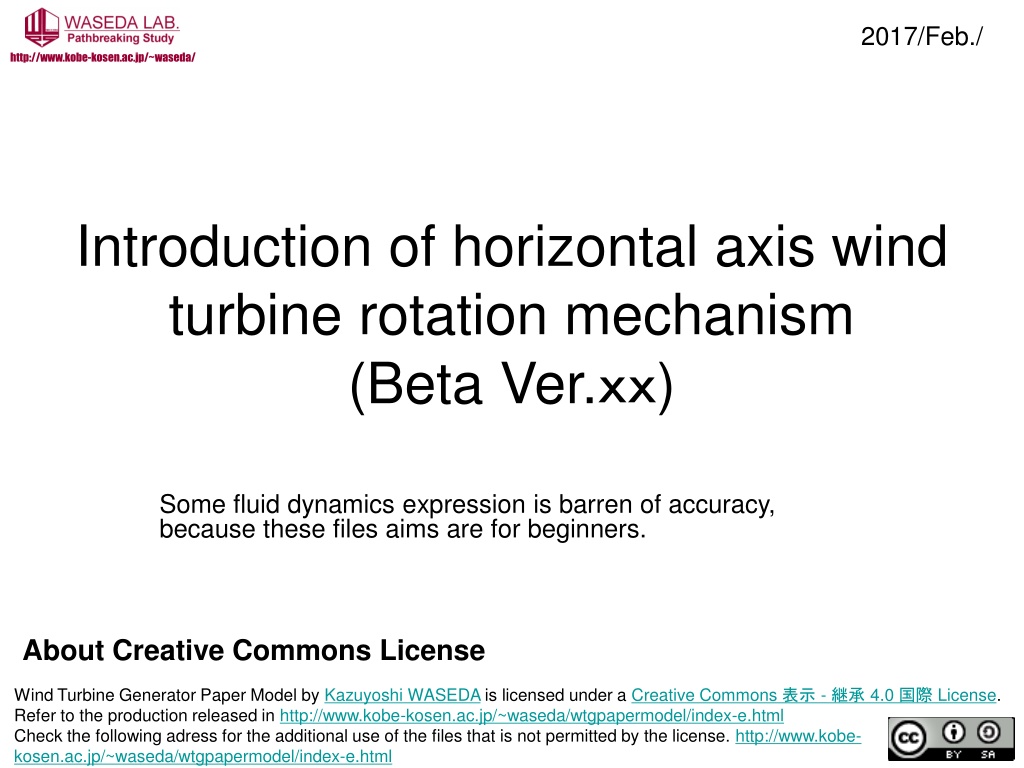

Introduction of horizontal axis wind
turbine rotation mechanism
(Beta Ver.
xx
)
A
b
o
u
t
C
r
e
a
t
i
v
e
C
o
m
m
o
n
s
L
i
c
e
n
s
e
2017/Feb./

Wind Turbine Generator Paper Model by
is licensed under a
.
Refer to the production released in
Check the following adress for the additional use of the files that is not permitted by the license.kosen.ac.jp/~waseda/wtgpapermodel/index-e.htmlhttp://www.kobe-http://www.kobe-kosen.ac.jp/~waseda/wtgpapermodel/index-e.htmlLicense国際 4.0 継承 - 表示 Creative Commons Kazuyoshi WASEDA
Some fluid dynamics expression is barren of accuracy,
because these files aims are for beginners.
http://www.kobe-kosen.ac.jp/~waseda/

Contents
•
V
ariety
of
horizontal axis wind turbine
•
Foundation of Fluid dynamics and Airfoil
element theory
•
H
orizontal axis wind turbine rotation mechanism
•
What is Reynolds Number ?
V
ariety
of
horizontal axis
wind turbine
Up wind type
-
Down wind type
Up wind type
Down wind type
Rotor blade
located
at front side of the tower
Rotor blade
located
at back side of the tower
Wind
Wind
Names of parts
•
Airfoil
•
Rotor Blade
•
Nacelle
•
Hub (root of the blade)
•
Spiner
•
Tower
Rotor Blade
Nacelle
Tower
Spinner
Hub
Airfoil
Horizontal axis wind turbine rotation
mechanism
Before the
wind turbine
rotation mechanism
,,,
Foundation of Fluid dynamics and
Airfoil element theory
NASA:Incorrect Lift Theory
http://www.grc.nasa.gov/WWW/k-12/airplane/wrong1.html
NASA:Incorrect Lift Theory #2
http://www.grc.nasa.gov/WWW/k-12/airplane/wrong2.html
http://jein.jp/jifs/scientific-topics/887-topic49.html
飛行機はなぜ飛ぶかのかまだ分からない
?? - NPO
法人 知的人材ネットワーク・あいんしゅたいん
M
o
r
e
a
c
c
u
r
a
t
e
i
n
f
o
r
m
a
t
i
o
n
o
f
f
l
u
i
d
d
y
n
a
m
i
c
s
a
n
d
t
h
e
b
l
a
d
e
e
l
e
m
e
n
t
t
h
e
o
r
y
日本機械学会 流体工学部門:活動内容:楽しい流れの実験教室
http://www.jsme-fed.org/experiment/
S
e
e
W
i
k
i
p
e
d
i
a
:
M
i
s
u
n
d
e
r
s
t
a
n
d
i
n
g
s
a
b
o
u
t
t
h
e
g
e
n
e
r
a
t
i
o
n
o
f
l
i
f
t
L
i
f
t
(
f
o
r
c
e
)
http://en.wikipedia.org/wiki/Bernoulli%27s_principle#Misunderstandings_about_the_generation_of_lift
http://en.wikipedia.org/wiki/Lift_%28force%29
Lift and Drag
•
Lift
: Normal force caused by flow
•
Drag:
P
arallel
force caused by flow
Flow
Airfoil
Airfoil: The shape which maximize the lift and minimize the drag
L
:
Lift
D
:
Drag
It’s relatively same state!
Flow
airfoil
L
:
Lift
D
:
Drag
No Flow
airfoil
L
:
Lift
D
:
Drag
Move forward [airfoil]
Relatively
same state
Put an airfoil into the air flow = Move forward an airfoil in the (no flow) air
Law of continuity (Flow rate)
Q[m
3
/s]=A[m
2
]V[m/s]
=
constant
Flow Rate Q[m
3
/s]=
A
1
V
1
=A
2
V
2
=Constant
Q: flow rate[m
3
/s]
A
:
Cross section of flow [m
2
]
V
:
Flow velocity [m/s]
wide Cross section narrow
Slow Flow velocity Fast
A
1
A
2
V
1
V
2
Pipe
Pipe
Broad Small
What’s happened at around the airfoil ?
=upper surface flow velocity is higher
than lower surface
Flow
Narrow
cross section
upper surface flow velocity
is higher than lower surface
upper surface
lower surface
Bernoulli's principle
Flow
Dynamic Pressure + Piezometric head = const.
S
e
e
W
i
k
i
p
e
d
i
a
:
M
i
s
u
n
d
e
r
s
t
a
n
d
i
n
g
s
a
b
o
u
t
t
h
e
g
e
n
e
r
a
t
i
o
n
o
f
l
i
f
t
L
i
f
t
(
f
o
r
c
e
)
http://en.wikipedia.org/wiki/Bernoulli%27s_principle#Misunderstandings_about_the_generation_of_lift
http://en.wikipedia.org/wiki/Lift_%28force%29
V
:
Flow velocity [m/s]
p
:
Pressure[Pa]
ρ
:
Density of the fluid [kg/m
3
]
Flow
Lift force
Airfoil upper surface shape >>>
accelerate
flow velocity >>> Low pressure >> Lift force
Bernoulli's principle
p
1
p
2
V
1
V
2
p
1
V
1
p
1
V
1
p
1
>
p
2
V
1
V
1
,V
2
:
Flow velocity [m/s]
p
1
,p
2
:
Pressure[Pa]
ρ
:
Density of the fluid [kg/m
3
]
Some fluid dynamics expression is
barren of accuracy,,,
In any case
,
an airfoil
is
the shape that regarded low
drag
force
as high lift
force
It is ideal to Keep the AoA which shows
Largest Lift force-Drag force rate
•
What is
A
ngle
o
f
A
ttack (AoA:
)
•
Large AoA gives not only high lift force
(L)
but also high drag force
(D)
•
Larger AoA is trigger of the stall
(separation flow)
•
It is ideal to
Keep the AoA which shows
Largest Lift-Drag rate (L/D or C
L
/C
D
)
C
L
: Lift Coefficient
C
D
: Drag Coefficient
It is ideal to Keep the AoA which shows
Largest Lift force-Drag force rate
•
What is Angle of Attack (AoA:
)
•
Large AoA gives not only high lift force
(L)
but also high drag force
(D)
•
Larger AoA is trigger of the stall
(separation flow)
•
It is ideal to
Keep the AoA which shows
Largest Lift-Drag rate (L/D or C
L
/C
D
)
C
L
: Lift Coefficient
C
D
: Drag Coefficient
What is Angle of Attack (AoA:
)
Flow
Lift force
Drag force
AoA:
The angle of attack is the angle between the chord line of an airfoil and the oncoming air.
It is ideal to Keep the AoA which shows
Largest Lift force-Drag force rate
•
What is Angle of Attack (AoA:
)
•
Large AoA gives not only high lift force
(L)
but also high drag force
(D)
•
Larger AoA is trigger of the stall
(separation flow)
•
It is ideal to
Keep the AoA which shows
Largest Lift-Drag rate (L/D or C
L
/C
D
)
C
L
: Lift Coefficient
C
D
: Drag Coefficient
Large AoA gives not only high lift
force
(L)
but also high drag force
(D)
Flow
Large lift force
Large drag force too
Large AoA
It is ideal to Keep the AoA which shows
Largest Lift force-Drag force rate
•
What is Angle of Attack (AoA:
)
•
Large AoA gives not only high lift force
(L)
but also high drag force
(D)
•
Larger AoA is trigger of the stall
(separation flow)
•
It is ideal to
Keep the AoA which shows
Largest Lift-Drag rate (L/D or C
L
/C
D
)
C
L
: Lift Coefficient
C
D
: Drag Coefficient
Larger AoA is trigger of the stall
(separation flow )
Flow
Significantly decreases
the lift force
Significantly increases
the drag force
Larger AoA
Stall
Separation flow
(airfoil
performance is
as same as
simple flat panel)
It is ideal to
Keep the AoA which
shows Largest Lift-Drag rate (L/D or
C
L
/C
D
)
[Carry out the performance test of airfoil in all AoA range]
AoA:
0
o
Stall
Lift
Drag
Large AoA gives not only
high lift force(L)
but also
high drag force(D)
C
L
: Lift Coefficient
C
D
: Drag Coefficient
Glide ratio
[Lift-Drag rate]
L/D[C
L/
C
D
]
Stall
L/D maximum
AoA which shows
Largest Lift-Drag rate
AoA:
0
o
H
orizontal axis wind turbine
rotation mechanism
Blade plane of
rotation
H
orizontal axis wind turbine rotation
mechanism
v=r
[m/s]
Using Microsoft Power Point animation function
Horizontal axis wind turbine rotation
mechanism
Wind
W[m/s]
v=r
[m/s]
Apparent wind
V[m/s]
Blade plane of
rotation
Using Microsoft Power Point animation function
Altogether
"Large Lift-Drag rate" means "Wind turbine rotate"
Why the wind turbine
blade is twisted?
Why the wind turbine blade is twisted?
ω
:
angular velocity [rad/s]
There is velocity difference between at the root and the tip of the blade
r
1
r
2
<
The tip of the blade is higher in
rotational speed than the root
v
2
v
1
T
:time
Blade plane of
rotation
Wind
W[m/s]
v=r
[m/s]
Apparent wind
V[m/s]
When it suppose to be
the central position of the blade
When it suppose to be
the tip of the blade
Blade plane of
rotation
Wind
W[m/s]
v=r
[m/s]
Apparent wind
V[m/s]
When it suppose to be
the root of the blade
Blade plane of
rotation
Wind
W[m/s]
v=r
[m/s]
Apparent wind
V[m/s]
The image of AoA from tip to root
is…
Blade plane of
rotation
Wind
W[m/s]
v=r
[m/s]
Apparent wind
V[m/s]
Blade plane of
rotation
Wind
W[m/s]
v=r
[m/s]
Apparent wind
V[m/s]
Blade plane of
rotation
Wind
W[m/s]
v=r
[m/s]
Apparent wind
V[m/s]
Blade plane of
rotation
Wind
W[m/s]
v=r
[m/s]
Apparent wind
V[m/s]
Blade plane of
rotation
Wind
W[m/s]
v=r
[m/s]
Apparent wind
V[m/s]
Blade plane of
rotation
Wind
W[m/s]
v=r
[m/s]
Apparent wind
V[m/s]
Blade plane of
rotation
Wind
W[m/s]
v=r
[m/s]
Apparent wind
V[m/s]
Blade plane of
rotation
Wind
W[m/s]
Apparent wind
V[m/s] at root
of the blade
If Blade is not twisted(straight),
AoA is not optimized
Apparent wind
V[m/s]
at center position of the blade
Apparent wind
V[m/s]
at tip of the blade
-> Optimized the AoA(
) for each blade position
=twist the blade
Optimized the AoA(
) for each blade position
Blade plane of
rotation
Wind
W[m/s]
v=r
[m/s]
Apparent wind
V[m/s]
Blade plane of
rotation
Wind
W[m/s]
v=r
[m/s]
Apparent wind
V[m/s]
Optimized the AoA(
) for each blade position
Blade plane of
rotation
Wind
W[m/s]
v=r
[m/s]
Apparent wind
V[m/s]
Optimized the AoA(
) for each blade position
Blade plane of
rotation
Wind
W[m/s]
v=r
[m/s]
Apparent wind
V[m/s]
Optimized the AoA(
) for each blade position
Blade plane of
rotation
Wind
W[m/s]
v=r
[m/s]
Apparent wind
V[m/s]
Optimized the AoA(
) for each blade position
Blade plane of
rotation
Wind
W[m/s]
v=r
[m/s]
Apparent wind
V[m/s]
Optimized the AoA(
) for each blade position
Blade plane of
rotation
Wind
W[m/s]
v=r
[m/s]
Apparent wind
V[m/s]
Optimized the AoA(
) for each blade position
Blade plane of
rotation
Wind
W[m/s]
Apparent wind
V[m/s] at root
of the blade
=the wind turbine blade is twisted
Apparent wind
V[m/s] at center position of the blade
Apparent wind
V[m/s] at tip of the blade
Actually, airfoil shape is different for each position of the
blade, because of apparent wind velocity difference.
Optimized the AoA(
) for each blade position
If the rotor blade rotation
stopped…
If the rotor blade rotation stopped…
Blade plane of
rotation
v=r
[m/s]=0
What it does?
Blade plane of
rotation
Wind
W[m/s]
v=r
[m/s]=0
①
Change the pitch angle
What it does?
If the rotor blade rotation stopped…
or…
If the rotor blade rotation stopped…
Blade plane of
rotation
② give more peripheral velocity[starting torque]
This slide is using Microsoft PowerPoint animation
What it does?
If the wind speed change?
Wind stops or gust of wind blew!
If the wind speed change?
Blade plane of
rotation
Wind
W[m/s]
v=r
[m/s]
Apparent wind
V[m/s]
If wind stops
Blade plane of
rotation
Wind
W[m/s]
v=r
[m/s]
Apparent wind
V[m/s]
AoA(a) get small => Lift will reduce
If the wind speed change?
If wind stops
If the wind speed change?
Blade plane of
rotation
Wind
W[m/s]
v=r
[m/s]
Apparent wind
V[m/s]
If wind stops
AoA(a) get small => Lift will reduce
Change the
angle[pitch angle]!
If the wind speed change?
Blade plane of
rotation
Wind
W[m/s]
v=r
[m/s]
Apparent wind
V[m/s]
Windblast [gusty wind]
If the wind speed change?
Blade plane of
rotation
Wind
W[m/s]
v=r
[m/s]
Apparent wind
V[m/s]
AoA(a) get big => Lift will reduce [stall]
Windblast [gusty wind]
If the wind speed change?
Blade plane of
rotation
Wind
W[m/s]
v=r
[m/s]
Apparent wind
V[m/s]
AoA(a) get big => Lift will reduce [stall]
Change the
angle[pitch angle]!
Windblast [gusty wind]
If the wind speed change?
Always control the pitch angle
but
Wind turbine blade is heavy and pitch angle
control is slower pace
Performance of wind turbine blade is
not good for sensitive to AoA
AoA[
]
0°
Max
Stall
If wind speed is
changes=AoA changes
[See page 57-63]
Glide ratio
[Lift-Drag rate]
L/D[C
L/
C
D
]
AoA[
]
Great performance but too much
sensitive to AoA
narrow AoA range
0°
Max performance is low
but good performance at
wide AoA range
Good performance for
wind turbine blade
wide AoA range
Glide ratio[Lift-Drag rate]
L/D[C
L/
C
D
]
What is Reynolds number?
What is Re?
V :
Apparent (wind) velocity [m/s]
c:chord [m]
: The dynamic viscosity of the fluid (
=
/
1.502x10
−5
) [m²/s]
: The kinematic viscosity of the fluid ([Pa·s],
[N·s/m²] , [kg/(m·s)])
: The density of the fluid [kg/m³]
(1.203 kg/m³)
The Reynolds number is,,,
Inertial forces
Viscous forces
c:chord
Small
model
car
Full size
real car
If Reynolds
number is
same
flow situation
is same
-> Dimensionless quantity
-> The ratio of inertial forces to viscous forces within a fluid.
-> Used in the scaling of similar but different-sized flow situations, such as between
an aircraft model in a wind tunnel and the full size version.
In the case of wind turbine
Low
velocity
big size
chord
The dynamic
viscosity of the air
[same}
Small scale model wind turbine
Real wind turbine
If Reynolds
number is
same
flow situation
is same
High
velocity
small size
chord
Small scale wind
turbine model in
a wind tunnel
Real wind
turbine
Explore the world of horizontal axis wind turbines through an introduction to the rotation mechanism and foundational concepts of fluid dynamics and airfoil theory. Delve into Reynolds Number, lift and drag forces, and the components of wind turbines. Gain insights into the misconceptions surrounding lift generation and learn how shape optimization impacts turbine efficiency.

Download Presentation

Please find below an Image/Link to download the presentation.
The content on the website is provided AS IS for your information and personal use only. It may not be sold, licensed, or shared on other websites without obtaining consent from the author.If you encounter any issues during the download, it is possible that the publisher has removed the file from their server.
You are allowed to download the files provided on this website for personal or commercial use, subject to the condition that they are used lawfully. All files are the property of their respective owners.
The content on the website is provided AS IS for your information and personal use only. It may not be sold, licensed, or shared on other websites without obtaining consent from the author.
E N D
Presentation Transcript
2017/Feb./ http://www.kobe-kosen.ac.jp/~waseda/ Introduction of horizontal axis wind turbine rotation mechanism (Beta Ver. ) Some fluid dynamics expression is barren of accuracy, because these files aims are for beginners. About Creative Commons License Wind Turbine Generator Paper Model by Kazuyoshi WASEDA is licensed under a Creative Commons - 4.0 License. Refer to the production released in http://www.kobe-kosen.ac.jp/~waseda/wtgpapermodel/index-e.html Check the following adress for the additional use of the files that is not permitted by the license. http://www.kobe- kosen.ac.jp/~waseda/wtgpapermodel/index-e.html
Contents Variety of horizontal axis wind turbine Foundation of Fluid dynamics and Airfoil element theory Horizontal axis wind turbine rotation mechanism What is Reynolds Number ?
Variety of horizontal axis wind turbine
Up wind type - Down wind type
Up wind type Down wind type Wind Wind Rotor blade located at front side of the tower Rotor blade located at back side of the tower
Names of parts Airfoil Rotor Blade Nacelle Hub (root of the blade) Spiner Tower Rotor Blade Nacelle Spinner Airfoil Hub Tower
Horizontal axis wind turbine rotation mechanism
Before the wind turbine rotation mechanism,,, Foundation of Fluid dynamics and Airfoil element theory See Wikipedia: Misunderstandings about the generation of lift http://en.wikipedia.org/wiki/Bernoulli%27s_principle#Misunderstandings_about_the_generation_of_lift Lift (force) http://en.wikipedia.org/wiki/Lift_%28force%29 More accurate information of fluid dynamics and the blade element theory NASA:Incorrect Lift Theory http://www.grc.nasa.gov/WWW/k-12/airplane/wrong1.html NASA:Incorrect Lift Theory #2 http://www.grc.nasa.gov/WWW/k-12/airplane/wrong2.html
Lift and Drag Lift: Normal force caused by flow Drag: Parallel force caused by flow L Lift Airfoil Flow D Drag Airfoil: The shape which maximize the lift and minimize the drag
Its relatively same state! Put an airfoil into the air flow = Move forward an airfoil in the (no flow) air L Lift airfoil Flow D Drag Relatively same state L Lift airfoil No Flow D Drag Move forward [airfoil]
Law of continuity (Flow rate) Q[m3/s]=A[m2]V[m/s] constant Q: flow rate[m3/s] A Cross section of flow [m2] Pipe V Flow velocity [m/s] Broad Small wide Cross section narrow A2 A1 Pipe V2 Slow Flow velocity Fast V1 Flow Rate Q[m3/s]=A1V1=A2V2=Constant
Whats happened at around the airfoil ? =upper surface flow velocity is higher than lower surface Narrow cross section upper surface flow velocity is higher than lower surface upper surface Flow lower surface
Bernoulli's principle p = + 1 2 . V const V Flow velocity [m/s] p Pressure[Pa] Density of the fluid [kg/m3] 2 Dynamic Pressure + Piezometric head = const. Flow See Wikipedia: Misunderstandings about the generation of lift http://en.wikipedia.org/wiki/Bernoulli%27s_principle#Misunderstandings_about_the_generation_of_lift Lift (force) http://en.wikipedia.org/wiki/Lift_%28force%29
Bernoulli's principle 1 2 2 V + = p1>p2 1 p p 2 + = . 1 2 V const 1 2 2 V1,V2 Flow velocity [m/s] p1,p2 Pressure[Pa] Density of the fluid [kg/m3] Lift force p2 V2 p1 V1 Flow p1 V1 p1 V1 Airfoil upper surface shape >>> accelerate flow velocity >>> Low pressure >> Lift force
Some fluid dynamics expression is barren of accuracy,,, In any case, an airfoil is the shape that regarded low drag force as high lift force
It is ideal to Keep the AoA which shows Largest Lift force-Drag force rate What is Angle of Attack (AoA: ) Large AoA gives not only high lift force(L) but also high drag force(D) Larger AoA is trigger of the stall (separation flow) It is ideal to Keep the AoA which shows Largest Lift-Drag rate (L/D or CL/CD) CL: Lift Coefficient CD: Drag Coefficient
It is ideal to Keep the AoA which shows Largest Lift force-Drag force rate What is Angle of Attack (AoA: ) Large AoA gives not only high lift force(L) but also high drag force(D) Larger AoA is trigger of the stall (separation flow) It is ideal to Keep the AoA which shows Largest Lift-Drag rate (L/D or CL/CD) CL: Lift Coefficient CD: Drag Coefficient
What is Angle of Attack (AoA: ) The angle of attack is the angle between the chord line of an airfoil and the oncoming air. AoA: Lift force Flow Drag force
It is ideal to Keep the AoA which shows Largest Lift force-Drag force rate What is Angle of Attack (AoA: ) Large AoA gives not only high lift force(L) but also high drag force(D) Larger AoA is trigger of the stall (separation flow) It is ideal to Keep the AoA which shows Largest Lift-Drag rate (L/D or CL/CD) CL: Lift Coefficient CD: Drag Coefficient
Large AoA gives not only high lift force(L) but also high drag force(D) Large AoA Large lift force Flow Large drag force too
It is ideal to Keep the AoA which shows Largest Lift force-Drag force rate What is Angle of Attack (AoA: ) Large AoA gives not only high lift force(L) but also high drag force(D) Larger AoA is trigger of the stall (separation flow) It is ideal to Keep the AoA which shows Largest Lift-Drag rate (L/D or CL/CD) CL: Lift Coefficient CD: Drag Coefficient
Larger AoA is trigger of the stall (separation flow ) Separation flow (airfoil performance is as same as simple flat panel) Significantly decreases the lift force Larger AoA Stall Flow Significantly increases the drag force
It is ideal to Keep the AoA which shows Largest Lift-Drag rate (L/D or CL/CD) [Carry out the performance test of airfoil in all AoA range]
Large AoA gives not only high lift force(L) but also high drag force(D) Lift CL: Lift Coefficient CD: Drag Coefficient Stall Drag 0o AoA:
Glide ratio [Lift-Drag rate] L/D[CL/CD] L/D maximum Stall AoA which shows Largest Lift-Drag rate 0o AoA:
Horizontal axis wind turbine rotation mechanism
Horizontal axis wind turbine rotation mechanism v=r [m/s] v=r [m/s] Blade plane of rotation Wind W[m/s] Apparent wind V[m/s] Using Microsoft Power Point animation function
Horizontal axis wind turbine rotation mechanism Lift Drag v=r [m/s] Blade plane of rotation Wind W[m/s] Apparent wind V[m/s] Rotation direction force by lift Rotation direction force by drag(opposite direction) The difference is Actual Rotation direction force Using Microsoft Power Point animation function
Altogether "Large Lift-Drag rate" means "Wind turbine rotate"
Why the wind turbine blade is twisted?
Why the wind turbine blade is twisted? There is velocity difference between at the root and the tip of the blade 2 r = = v r 2 = r2 T T angular velocity [rad/s] r1 T:time < 2 2 r r = = = = 1 v r 2 v r 1 1 2 2 T T v1 The tip of the blade is higher in rotational speed than the root v2
When it suppose to be the central position of the blade v=r [m/s] Blade plane of rotation Wind W[m/s] Apparent wind V[m/s]
When it suppose to be the tip of the blade v=r [m/s] Blade plane of rotation Wind W[m/s] Apparent wind V[m/s]
When it suppose to be the root of the blade v=r [m/s] Blade plane of rotation Wind W[m/s] Apparent wind V[m/s]
v=r[m/s] Blade plane of rotation Wind W[m/s] Apparent wind V[m/s]
v=r[m/s] Blade plane of rotation Wind W[m/s] Apparent wind V[m/s]
v=r[m/s] Blade plane of rotation Wind W[m/s] Apparent wind V[m/s]
v=r[m/s] Blade plane of rotation Wind W[m/s] Apparent wind V[m/s]
v=r[m/s] Blade plane of rotation Wind W[m/s] Apparent wind V[m/s]
v=r[m/s] Blade plane of rotation Wind W[m/s] Apparent wind V[m/s]
v=r[m/s] Blade plane of rotation Wind W[m/s] Apparent wind V[m/s]
If Blade is not twisted(straight), AoA is not optimized -> Optimized the AoA( ) for each blade position =twist the blade Blade plane of rotation Wind W[m/s] Apparent wind V[m/s] at root Apparent wind V[m/s] at center position of the blade of the blade Apparent wind V[m/s] at tip of the blade
Optimized the AoA() for each blade position v=r [m/s] Blade plane of rotation Wind W[m/s] Apparent wind V[m/s]
Optimized the AoA() for each blade position v=r [m/s] Blade plane of rotation Wind W[m/s] Apparent wind V[m/s]
Optimized the AoA() for each blade position v=r [m/s] Blade plane of rotation Wind W[m/s] Apparent wind V[m/s]
Optimized the AoA() for each blade position v=r [m/s] Blade plane of rotation Wind W[m/s] Apparent wind V[m/s]
Optimized the AoA() for each blade position v=r [m/s] Blade plane of rotation Wind W[m/s] Apparent wind V[m/s]
Optimized the AoA() for each blade position v=r [m/s] Blade plane of rotation Wind W[m/s] Apparent wind V[m/s]
Optimized the AoA() for each blade position v=r [m/s] Blade plane of rotation Wind W[m/s] Apparent wind V[m/s]


")


")


 but also high")


,")
 for each blade position")
 for each blade position")
 for each blade position")
 for each blade position")
 for each blade position")
 for each blade position")
 for each blade position")