HIGHWIND Hardware: Team and Responsibilities Overview
H
I
G
H
W
I
N
D
H
a
r
d
w
a
r
e
T
h
o
r
b
j
ö
r
n
J
ö
r
g
e
r
L
e
h
r
s
t
u
h
l
f
ü
r
S
y
s
t
e
m
t
h
e
o
r
i
e
I
n
s
t
i
t
u
t
f
ü
r
M
i
k
r
o
s
y
s
t
e
m
t
e
c
h
n
i
k
-
I
M
T
E
K
A
l
b
e
r
t
-
L
u
d
w
i
g
s
-
U
n
i
v
e
r
s
i
t
ä
t
F
r
e
i
b
u
r
g
12.06.2015
Scientific Advisory Board Meeting 2015 – Thorbjörn Jörger
- 2 -
R
e
s
p
o
n
s
i
b
i
l
i
t
i
e
s
All HIGHWIND hardware
Carousel
Airplanes
Sensors
Actuators
Components communication and interfacing
Interface definition (BETCOM)
Implementing communication
Control software
Carousel (OROCOS)
Flight hardware
Visualisation
12.06.2015
Scientific Advisory Board Meeting 2015 – Thorbjörn Jörger
- 3 -
T
e
a
m
:
C
o
m
m
u
n
i
c
a
t
i
o
n
&
V
i
s
u
a
l
i
s
a
t
i
o
n
Elias Rosch:
B. Sc. Embedded Systems Engineering
Currently master studies ESE
With HIGHWIND since April 2014
Julian Reimer
B. Sc. Embedded Systems Engineering
Currently master studies ESE
With HIGHWIND since December 2014
12.06.2015
Scientific Advisory Board Meeting 2015 – Thorbjörn Jörger
- 4 -
T
e
a
m
:
F
l
i
g
h
t
s
o
f
t
w
a
r
e
Fabian Girrbach
B. Sc. Embedded Systems Engineering
Currently master thesis ESE
With HIGHWIND since April 2014
Maximilian Ernestus
B. Sc. Informatik
Currently master studies Cognitive Sciences
With HIGHWIND since March 2015
12.06.2015
Scientific Advisory Board Meeting 2015 – Thorbjörn Jörger
- 5 -
T
e
a
m
:
F
l
i
g
h
t
h
a
r
d
w
a
r
e
Ben Schleusener
B. Sc. Microsystems Engineering
Currently master studies MST
With HIGHWIND since September 2013
Joanna Greulich
Currently bachelor studies MST
With HIGHWIND since April 2015
12.06.2015
Scientific Advisory Board Meeting 2015 – Thorbjörn Jörger
- 6 -
C
a
r
o
u
s
e
l
T
a
r
g
e
t
:
B
l
a
c
k
B
o
x
f
o
r
u
s
e
r
s
PLC and motor drives
Fixed all bugs
Hard coded limits for safety
Stable communication to Groundstation
Clean interface to OROCOS
Safety measures implemented
Warning lights
Speed limits
N
o
w
:
F
i
r
e
a
n
d
F
o
r
g
e
t
12.06.2015
Scientific Advisory Board Meeting 2015 – Thorbjörn Jörger
- 7 -
R
o
d
m
o
u
n
t
e
d
h
a
l
f
-
w
i
n
g
a
i
r
p
l
a
n
e
Intermediate step to tethered flight
Only two degrees of freedom
Much easier to control
Easy task for testing the setup
Hard limits for elevation and rotation
No dangerous angles of attack
Absolute angular sensors
Accurate position over ground
But angle of attack is most likely different
Reference for state estimation with IMUs
Clean interface to OROCOS
Black Box for experimenters
12.06.2015
Scientific Advisory Board Meeting 2015 – Thorbjörn Jörger
- 8 -
S
e
n
s
o
r
f
u
s
i
o
n
It is desirable to have all sensors fused at one point
Time keeping and synchronisation much easier
Easier to maintain
Fast and low jitter connection to controller
More time for NMPC calculations in each time step
12.06.2015
Scientific Advisory Board Meeting 2015 – Thorbjörn Jörger
- 9 -
S
e
n
s
o
r
f
u
s
i
o
n
It is desirable to have all sensors fused at one point
Time keeping and synchronisation much easier
Easier to maintain
Fast and low jitter connection to controller
More time for NMPC calculations in each time step
Past:
12.06.2015
Scientific Advisory Board Meeting 2015 – Thorbjörn Jörger
- 10 -
S
e
n
s
o
r
f
u
s
i
o
n
It is desirable to have all sensors fused at one point
Time keeping and synchronisation much easier
Easier to maintain
Fast and low jitter connection to controller
More time for NMPC calculations in each time step
Present:
12.06.2015
Scientific Advisory Board Meeting 2015 – Thorbjörn Jörger
- 11 -
S
e
n
s
o
r
f
u
s
i
o
n
It is desirable to have all sensors fused at one point
Time keeping and synchronisation much easier
Easier to maintain
Fast and low jitter connection to controller
More time for NMPC calculations in each time step
Future:
12.06.2015
Scientific Advisory Board Meeting 2015 – Thorbjörn Jörger
- 12 -
S
e
n
s
o
r
f
u
s
i
o
n
It is desirable to have all sensors fused at one point
Time keeping and synchronisation much easier
Easier to maintain
Fast and low jitter connection to controller
More time for NMPC calculations in each time step
Future?
29.05.2015
Group Retreat 2015 - Seebrugg - Thorbjörn Jörger
- 13 -
T
i
m
e
k
e
e
p
i
n
g
Each measurement gets a time stamp in a unified time frame
From the time stamping on, all delays can be taken into account
by the controller and the state estimator
System is now calibration free
Execution time for actuator commands can be set
But need for synchronous clocks
29.05.2015
Group Retreat 2015 - Seebrugg - Thorbjörn Jörger
- 14 -
C
l
o
c
k
s
y
n
c
h
r
o
n
i
z
a
t
i
o
n
Reference pulse which occurs simultaneous in both systems
1PPS signal of GPS is the natural choice for outdoor experiments
no information exchange between systems necessary
Absolute and jump-free GPS time reference is also available
Small jitter (15-50 ns) with cheap equipment, < 1 ns with better equipment
Indoor Environment usually has to low signal strength
29.05.2015
Group Retreat 2015 - Seebrugg - Thorbjörn Jörger
- 15 -
C
l
o
c
k
s
y
n
c
h
r
o
n
i
z
a
t
i
o
n
Reference pulse which occurs simultaneous in both systems
1PPS signal of GPS is the natural choice for outdoor experiments
no information exchange between systems necessary
Absolute and jump-free GPS time reference is also available
Small jitter (15-50 ns) with cheap equipment, < 1 ns with better equipment
Indoor Environment usually has to low signal strength
To much manpower necessary
Nice to have
Necessary
29.05.2015
Group Retreat 2015 - Seebrugg - Thorbjörn Jörger
- 16 -
C
l
o
c
k
s
y
n
c
h
r
o
n
i
z
a
t
i
o
n
Reference pulse which occurs simultaneous in both systems
“1PPS” signal generated by BeagleBone
Simple and reliant
Quick to implement
Hardware programming portable for real 1PPS
Additional cables necessary (bad for tethered flight)
29.05.2015
Group Retreat 2015 - Seebrugg - Thorbjörn Jörger
- 17 -
B
E
T
P
R
O
T
:
O
v
e
r
v
i
e
w
Clean message based interface between all components
Defines messages containing data, controls and configuration
Based on protobuf, which is already used in OROCOS
High flexibility through platform and protocol independence
29.05.2015
Group Retreat 2015 - Seebrugg - Thorbjörn Jörger
- 18 -
B
E
T
P
R
O
T
:
M
e
s
s
a
g
e
s
Messages are defined as either:
Required (exactly one message of this type required per packet)
Optional (zero or one message of this type contained per packet)
Repeated (zero to multiple messages of this type contained per packet)
This allows high flexibility, sensors can be added, cconfigured or neglected easily
Messages can be nested:
msg BETPROTO:
required msg BETCALL
•
required uint32 pps
•
required uint32_t ticks
•
repeated msg Airspeed
•
required uint32_t pps
•
required uint32_t ticks
•
required uint32_t airspeed_raw
•
optional uint32_t debug_info
…
msg BETPUSH
…
H
I
G
H
W
I
N
D
C
o
m
m
u
n
i
c
a
t
i
o
n
a
n
d
V
i
s
u
a
l
i
s
a
t
i
o
n
E
l
i
a
s
R
o
s
c
h
,
J
u
l
i
a
n
R
e
i
m
e
r
L
e
h
r
s
t
u
h
l
f
ü
r
S
y
s
t
e
m
t
h
e
o
r
i
e
I
n
s
t
i
t
u
t
f
ü
r
M
i
k
r
o
s
y
s
t
e
m
t
e
c
h
n
i
k
-
I
M
T
E
K
A
l
b
e
r
t
-
L
u
d
w
i
g
s
-
U
n
i
v
e
r
s
i
t
ä
t
F
r
e
i
b
u
r
g
12.06.2015
Scientific Advisory Board Meeting 2015 – Elias Rosch, Julian Reimer
- 20 -
P
r
o
t
o
c
o
l
:
B
e
t
P
r
o
t
Communication between
Groundstation and BB
via Ethernet / TCP
Communication Framework ZMQ
Messages defined via Google
Protobuf:
BetCall contains Sensordata
BetPush contains Actuatordata
12.06.2015
Scientific Advisory Board Meeting 2015 – Elias Rosch, Julian Reimer
- 21 -
B
e
t
C
a
l
l
Message generated by BB
Submessages contain:
Values for different axes
Timing information
Receiver
Forwards messages to visualizer
unpacks messages into the
datastructure Sensorcontainer
OROCOS handles
Sensorcontainer
12.06.2015
Scientific Advisory Board Meeting 2015 – Elias Rosch, Julian Reimer
- 22 -
B
e
t
P
u
s
h
Message generated by GS
OROCOS fills Actuatorcontainer
Sender packs messages from
Actuatorcontainer
12.06.2015
Scientific Advisory Board Meeting 2015 – Elias Rosch, Julian Reimer
- 23 -
B
e
t
C
o
n
f
Message generated by GS
OROCOS fills Configcontainer
Sender packs messages from
Configcontainer
12.06.2015
Scientific Advisory Board Meeting 2015 – Elias Rosch, Julian Reimer
- 24 -
B
e
t
V
i
s
u
a
l
i
z
e
r
Receives BetCall messages
Generates visual feedback from
current sensor- and timingdata
H
I
G
H
W
I
N
D
F
l
i
g
h
t
s
o
f
t
w
a
r
e
F
a
b
i
a
n
G
i
r
r
b
a
c
h
,
M
a
x
i
m
i
l
i
a
n
E
r
n
e
s
t
u
s
L
e
h
r
s
t
u
h
l
f
ü
r
S
y
s
t
e
m
t
h
e
o
r
i
e
I
n
s
t
i
t
u
t
f
ü
r
M
i
k
r
o
s
y
s
t
e
m
t
e
c
h
n
i
k
-
I
M
T
E
K
A
l
b
e
r
t
-
L
u
d
w
i
g
s
-
U
n
i
v
e
r
s
i
t
ä
t
F
r
e
i
b
u
r
g
12.06.2015
Scientific Advisory Board Meeting 2015 – Fabian Girrbach, Maximilian Ernestus
- 26 -
S
e
n
s
i
n
g
s
e
t
u
p
12.06.2015
Scientific Advisory Board Meeting 2015 – Fabian Girrbach, Maximilian Ernestus
- 27 -
W
h
y
t
w
o
f
r
a
m
e
w
o
r
k
s
?
H
I
G
H
W
I
N
D
F
l
i
g
h
t
h
a
r
d
w
a
r
e
B
e
n
S
c
h
l
e
u
s
e
n
e
r
,
J
o
a
n
n
a
G
r
e
u
l
i
c
h
L
e
h
r
s
t
u
h
l
f
ü
r
S
y
s
t
e
m
t
h
e
o
r
i
e
I
n
s
t
i
t
u
t
f
ü
r
M
i
k
r
o
s
y
s
t
e
m
t
e
c
h
n
i
k
-
I
M
T
E
K
A
l
b
e
r
t
-
L
u
d
w
i
g
s
-
U
n
i
v
e
r
s
i
t
ä
t
F
r
e
i
b
u
r
g
- 29 -
D
e
l
a
y
o
v
e
r
v
i
e
w
Standard ethernet is a bad choice for real time applications
12.06.2015
Scientific Advisory Board Meeting 2015 – Ben Schleusener, Joanna Greulich
- 30 -
D
e
l
a
y
o
v
e
r
v
i
e
w
Common time base is needed
Beaglebone generates 1PPS-signal
12.06.2015
Scientific Advisory Board Meeting 2015 – Ben Schleusener, Joanna Greulich
- 31 -
D
e
r
i
v
a
t
i
o
n
o
f
t
i
m
e
f
r
o
m
1
P
P
S
1PPS pulses are numbered consecutively
Intervals between 1PPS are counted with 8 MHz (ticks)
125 µs resolution
On rising flag, pulse counter is incremented and tick counter reset
Time stamp consist of ticks and pulse number
The pulse number is referenced in the GS to UTC time frame
The GS then calculates absolute timestamps for the measurements
12.06.2015
Scientific Advisory Board Meeting 2015 – Ben Schleusener, Joanna Greulich
12.06.2015
Scientific Advisory Board Meeting 2015 – Ben
- 32 -
C
h
a
l
l
e
n
g
e
H
e
l
v
e
t
i
c
a
2
8
p
t
You can also put pictures here if
they have the appropriate for
Helvetica is attached, otherwise
use Arial and tell me, I will change
it then (Arial is Helveticas bastard
son just by the way xD)
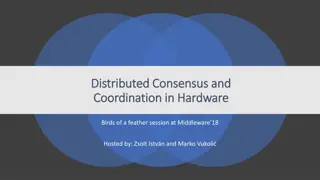
PW: mjolnir111!%%mjolnir
Explore the team and responsibilities behind the HIGHWIND hardware project, involving airplane components, sensors, actuators, communication interfaces, control software, and visualization. Meet the dedicated members working on flight software and hardware, all focused on enhancing communication, safety, and stability for this innovative system.

Download Presentation

Please find below an Image/Link to download the presentation.
The content on the website is provided AS IS for your information and personal use only. It may not be sold, licensed, or shared on other websites without obtaining consent from the author.If you encounter any issues during the download, it is possible that the publisher has removed the file from their server.
You are allowed to download the files provided on this website for personal or commercial use, subject to the condition that they are used lawfully. All files are the property of their respective owners.
The content on the website is provided AS IS for your information and personal use only. It may not be sold, licensed, or shared on other websites without obtaining consent from the author.
E N D
Presentation Transcript
HIGHWIND Hardware Thorbj rn J rger Lehrstuhl f r Systemtheorie Institut f r Mikrosystemtechnik - IMTEK Albert-Ludwigs-Universit t Freiburg
Responsibilities All HIGHWIND hardware Carousel Airplanes Sensors Actuators Components communication and interfacing Interface definition (BETCOM) Implementing communication Control software Carousel (OROCOS) Flight hardware Visualisation - 2 - 12.06.2015 Scientific Advisory Board Meeting 2015 Thorbj rn J rger
Team: Communication & Visualisation Elias Rosch: B. Sc. Embedded Systems Engineering Currently master studies ESE With HIGHWIND since April 2014 Julian Reimer B. Sc. Embedded Systems Engineering Currently master studies ESE With HIGHWIND since December 2014 - 3 - 12.06.2015 Scientific Advisory Board Meeting 2015 Thorbj rn J rger
Team: Flight software Fabian Girrbach B. Sc. Embedded Systems Engineering Currently master thesis ESE With HIGHWIND since April 2014 Maximilian Ernestus B. Sc. Informatik Currently master studies Cognitive Sciences With HIGHWIND since March 2015 - 4 - 12.06.2015 Scientific Advisory Board Meeting 2015 Thorbj rn J rger
Team: Flight hardware Ben Schleusener B. Sc. Microsystems Engineering Currently master studies MST With HIGHWIND since September 2013 Joanna Greulich Currently bachelor studies MST With HIGHWIND since April 2015 - 5 - 12.06.2015 Scientific Advisory Board Meeting 2015 Thorbj rn J rger
Carousel Target: Black Box for users PLC and motor drives Fixed all bugs Hard coded limits for safety Stable communication to Groundstation Clean interface to OROCOS Safety measures implemented Warning lights Speed limits Now: Fire and Forget - 6 - 12.06.2015 Scientific Advisory Board Meeting 2015 Thorbj rn J rger
Rod mounted half-wing airplane Intermediate step to tethered flight Only two degrees of freedom Much easier to control Easy task for testing the setup Hard limits for elevation and rotation No dangerous angles of attack Absolute angular sensors Accurate position over ground But angle of attack is most likely different Reference for state estimation with IMUs Clean interface to OROCOS Black Box for experimenters - 7 - 12.06.2015 Scientific Advisory Board Meeting 2015 Thorbj rn J rger
Sensor fusion It is desirable to have all sensors fused at one point Time keeping and synchronisation much easier Easier to maintain Fast and low jitter connection to controller More time for NMPC calculations in each time step - 8 - 12.06.2015 Scientific Advisory Board Meeting 2015 Thorbj rn J rger
Sensor fusion It is desirable to have all sensors fused at one point Time keeping and synchronisation much easier Easier to maintain Fast and low jitter connection to controller More time for NMPC calculations in each time step Past: - 9 - 12.06.2015 Scientific Advisory Board Meeting 2015 Thorbj rn J rger
Sensor fusion It is desirable to have all sensors fused at one point Time keeping and synchronisation much easier Easier to maintain Fast and low jitter connection to controller More time for NMPC calculations in each time step Present: - 10 - 12.06.2015 Scientific Advisory Board Meeting 2015 Thorbj rn J rger
Sensor fusion It is desirable to have all sensors fused at one point Time keeping and synchronisation much easier Easier to maintain Fast and low jitter connection to controller More time for NMPC calculations in each time step Future: - 11 - 12.06.2015 Scientific Advisory Board Meeting 2015 Thorbj rn J rger
Sensor fusion It is desirable to have all sensors fused at one point Time keeping and synchronisation much easier Easier to maintain Fast and low jitter connection to controller More time for NMPC calculations in each time step Future? - 12 - 12.06.2015 Scientific Advisory Board Meeting 2015 Thorbj rn J rger
Time keeping Each measurement gets a time stamp in a unified time frame From the time stamping on, all delays can be taken into account by the controller and the state estimator System is now calibration free Execution time for actuator commands can be set But need for synchronous clocks - 13 - 29.05.2015 Group Retreat 2015 - Seebrugg - Thorbj rn J rger
Clock synchronization Reference pulse which occurs simultaneous in both systems 1PPS signal of GPS is the natural choice for outdoor experiments no information exchange between systems necessary Absolute and jump-free GPS time reference is also available Small jitter (15-50 ns) with cheap equipment, < 1 ns with better equipment Indoor Environment usually has to low signal strength - 14 - 29.05.2015 Group Retreat 2015 - Seebrugg - Thorbj rn J rger
Clock synchronization Necessary Reference pulse which occurs simultaneous in both systems 1PPS signal of GPS is the natural choice for outdoor experiments no information exchange between systems necessary Absolute and jump-free GPS time reference is also available Small jitter (15-50 ns) with cheap equipment, < 1 ns with better equipment Indoor Environment usually has to low signal strength To much manpower necessary Nice to have - 15 - 29.05.2015 Group Retreat 2015 - Seebrugg - Thorbj rn J rger
Clock synchronization Reference pulse which occurs simultaneous in both systems 1PPS signal generated by BeagleBone Simple and reliant Quick to implement Hardware programming portable for real 1PPS Additional cables necessary (bad for tethered flight) - 16 - 29.05.2015 Group Retreat 2015 - Seebrugg - Thorbj rn J rger
BETPROT: Overview Clean message based interface between all components Defines messages containing data, controls and configuration Based on protobuf, which is already used in OROCOS High flexibility through platform and protocol independence - 17 - 29.05.2015 Group Retreat 2015 - Seebrugg - Thorbj rn J rger
BETPROT: Messages Messages are defined as either: Required (exactly one message of this type required per packet) Optional (zero or one message of this type contained per packet) Repeated (zero to multiple messages of this type contained per packet) This allows high flexibility, sensors can be added, cconfigured or neglected easily Messages can be nested: msg BETPROTO: required msg BETCALL required uint32 pps required uint32_t ticks repeated msg Airspeed required uint32_t pps required uint32_t ticks required uint32_t airspeed_raw optional uint32_t debug_info msg BETPUSH - 18 - 29.05.2015 Group Retreat 2015 - Seebrugg - Thorbj rn J rger
HIGHWIND Communication and Visualisation Elias Rosch, Julian Reimer Lehrstuhl f r Systemtheorie Institut f r Mikrosystemtechnik - IMTEK Albert-Ludwigs-Universit t Freiburg
Protocol: BetProt Flight- control Communication between Groundstation and BB BB Sensors Sensors Actuators via Ethernet / TCP Communication Framework ZMQ Messages defined via Google Protobuf: BetCall contains Sensordata BetPush contains Actuatordata BetCall BetPush GS BetCall Receiver Sender Visualizer Actuatorcontainer Sensorcontainer OROCOS - 20 - 12.06.2015 Scientific Advisory Board Meeting 2015 Elias Rosch, Julian Reimer
BetCall Message generated by BB Submessages contain: Values for different axes Timing information Receiver Forwards messages to visualizer unpacks messages into the datastructure Sensorcontainer OROCOS handles Sensorcontainer IMUs plane IMUs arm Gps Line angle Airspeed Angle of attack Dms Timestamp Ticks - 21 - 12.06.2015 Scientific Advisory Board Meeting 2015 Elias Rosch, Julian Reimer
BetPush Message generated by GS OROCOS fills Actuatorcontainer Sender packs messages from Actuatorcontainer Flaps Ailerons Rudder Elevator Ticks - 22 - 12.06.2015 Scientific Advisory Board Meeting 2015 Elias Rosch, Julian Reimer
BetVisualizer Receives BetCall messages Generates visual feedback from current sensor- and timingdata IMU plane IMU arm Line angle - 24 - 12.06.2015 Scientific Advisory Board Meeting 2015 Elias Rosch, Julian Reimer
HIGHWIND Flight software Fabian Girrbach, Maximilian Ernestus Lehrstuhl f r Systemtheorie Institut f r Mikrosystemtechnik - IMTEK Albert-Ludwigs-Universit t Freiburg
Sensing setup - 26 - 12.06.2015 Scientific Advisory Board Meeting 2015 Fabian Girrbach, Maximilian Ernestus
Why two frameworks? Paparazzi - Rich features for autonomous flying - Open source project with many experts involved - Dependencies between modules have to be considered - More complex code structure and debugging Arduino - Rich library and example database - Multi-purpose and multi- solution - In general lower quality of code - Focus on simplicity instead of performance Framework Pros: Learning Curve: - 27 - 12.06.2015 Scientific Advisory Board Meeting 2015 Fabian Girrbach, Maximilian Ernestus
HIGHWIND Flight hardware Ben Schleusener, Joanna Greulich Lehrstuhl f r Systemtheorie Institut f r Mikrosystemtechnik - IMTEK Albert-Ludwigs-Universit t Freiburg
Delay overview Standard ethernet is a bad choice for real time applications - 29 - 12.06.2015 Scientific Advisory Board Meeting 2015 Ben Schleusener, Joanna Greulich
Delay overview Common time base is needed Beaglebone generates 1PPS-signal - 30 - 12.06.2015 Scientific Advisory Board Meeting 2015 Ben Schleusener, Joanna Greulich
Derivation of time from 1PPS 1PPS pulses are numbered consecutively Intervals between 1PPS are counted with 8 MHz (ticks) 125 s resolution On rising flag, pulse counter is incremented and tick counter reset Time stamp consist of ticks and pulse number The pulse number is referenced in the GS to UTC time frame The GS then calculates absolute timestamps for the measurements - 31 - 12.06.2015 Scientific Advisory Board Meeting 2015 Ben Schleusener, Joanna Greulich
Challenge Helvetica 28 pt You can also put pictures here if they have the appropriate for Helvetica is attached, otherwise use Arial and tell me, I will change it then (Arial is Helveticas bastard son just by the way xD) PW: mjolnir111!%%mjolnir - 32 - 12.06.2015 Scientific Advisory Board Meeting 2015 Ben