Engineering Beam Analysis using Finite Element Method
Solve beam analysis problems involving deflections, rotations, and reaction forces using the finite element method. The examples provided cover scenarios with roller supports, spring supports, and internal hinges. Learn how to determine displacements, rotations, and element forces in beams of varying configurations.
Download Presentation

Please find below an Image/Link to download the presentation.
The content on the website is provided AS IS for your information and personal use only. It may not be sold, licensed, or shared on other websites without obtaining consent from the author.If you encounter any issues during the download, it is possible that the publisher has removed the file from their server.
You are allowed to download the files provided on this website for personal or commercial use, subject to the condition that they are used lawfully. All files are the property of their respective owners.
The content on the website is provided AS IS for your information and personal use only. It may not be sold, licensed, or shared on other websites without obtaining consent from the author.
E N D
Presentation Transcript
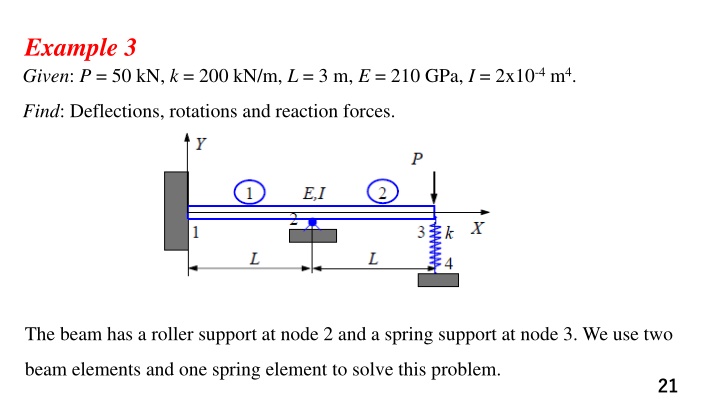
Example 3 Given: P = 50 kN, k = 200 kN/m, L = 3 m, E = 210 GPa, I = 2x10⁻⁴m4. Find: Deflections, rotations and reaction forces. The beam has a roller support at node 2 and a spring support at node 3. We use two beam elements and one spring element to solve this problem. 21
Solution: The spring stiffness matrix is given by, Adding this stiffness matrix to the global FE equation, We have, in which 22
We now apply the boundary conditions, The following reduced equation, Solving this equation, we obtain the deflection and rotations at node 2 and node 3, 24
From the global FE equation, we obtain the nodal reaction forces as, The free body diagram of the beam 25
Example 1 Determine the displacement and rotation at node 2 and the element forces for the uniform beam with an internal hinge at node 2 shown in the Figure. Let EI be a constant. 32
Solution We can consider the hinge as part of element 1. Therefore, with the hinge located at the right end of element 1, the stiffness matrix of element 1 with L=a is, we do not consider the hinge again as part of element 2. So we use the standard beam element stiffness matrix for element 2. 33
Superimposing the two stiffness equations and applying the boundary conditions 7
we obtain the total stiffness matrix and total set of equations as Solving this equation, we obtain 34
Simplifying this equation, we obtain the forces as we obtain the element 2 forces as 35
Example 2 36
Solution Discretize the beam into three elements, to determine element one stiffness matrix as Assume the hinge as part of element 2 the stiffness matrix as 37
Solution As the hinge is considered to be at the right end of element 2, we do not consider it to be part of element 3. So we use beam stiffness matrix to obtain the stiffness matrix as we assemble the global stiffness matrix as 38
Solution 39
Example 3 Given: E = 30x106psi, I = 65 in4, A = 6.8 in2 Find displacements and rotations of the two joints 1 and 2.
Solution For this example, we first convert the distributed load to its equivalent nodal loads.
In local coordinate system, the stiffness matrix for a general 2-D beam element is
For elements 2 and 3, we have the stiffness matrix in local system, where i=3, j=1 for element 2 and i=4, j=2 for element 3.
Transformation matrix T We have l = 0, m = 1 for both elements 2 and 3. Thus,
Using the transformation relation, we obtain the stiffness matrices in the global coordinate system for elements 2 and 3,
Assembling the global FE equation and noticing the following boundary conditions, we obtain the condensed FE equation,
Solving this, we get To calculate the reaction forces and moments at the two ends, we employ the element FE equations for element 2 and element 3. We obtain,
Example 4 As the first example of rigid plane frame analysis, The frame is fixed at nodes 1 and 4 and subjected to a positive horizontal force of 10,000 lb applied at node 2 and to a positive moment of 5000 lb-in. applied at node 3. The global-coordinate axes and the element lengths are shown in the figure. Let E =30x106psi and A =10 in2for all elements, and let I =200 in4for elements 1 and 3, and I =100 in4for element 2.
Solution we obtain the general transformed global stiffness matrix for a beam element that includes axial force, shear force, and bending moment effects as follows: Using this equation, we obtain the global stiffness matrices for each element.
Element 1 For element 1, the angle between the global x and the local x` axes is 90 (counterclockwise) because x` is assumed to be directed from node 1 to node 2. Therefore,
for element 1, we obtain the element global stiffness matrix as
Element 2 For element 2, the angle between x and x` is zero because x` is directed from node 2 to node 3. Therefore,
Element 3 For element 3, the angle between x and x` is 270 (or 90) because x` is directed from node 3 to node 4. Therefore, Superposition of k1, k2, k3and application of the boundary conditions u1=v1=f1=0 and u4=v4=f4= 0 at nodes 1 and 4 yield the reduced set of equations for a longhand solution as
Solving this equation for the displacements and rotations, we have
The element forces can now be obtained using for the displacements at node 2, we have
Then using k` from we obtain element 1 local forces as
Simplifying the equation, we obtain the local forces acting on element 1 as
Simplifying the equation, we obtain the local forces acting on element 1 as
Example 4 To illustrate the procedure for solving frames subjected to distributed loads, solve the rigid plane frame shown in the figure below. The frame is fixed at nodes 1 and 3 and subjected to a uniformly distributed load of 1000 lb/ft applied downward over element 2. The global-coordinate axes have been established at node 1. The element lengths are shown in the figure. Let E = 30x106psi, A = 100 in2, and I=1000 in4for both elements of the frame.
We then use the equation of global stiffness matrix to determine each element stiffness matrix: Element 1 Simplifying the equation, we obtain where only the parts of the stiffness matrix associated with degrees of freedom at node 2 are included because node 1 is fixed.
Element 2 Simplifying the equation, we obtain where, again, only the parts of the stiffness matrix associated with degrees of freedom at node 2 are included because node 3 is fixed.
On superimposing the stiffness matrices of the elements, the nodal forces and moments only at node 2 (because the structure is fixed at node 3), we have Solving the equation for the displacements and the rotation at node 2, we obtain
The local forces in each element can now be determined. The procedure for elements that are subjected to a distributed load must be applied to element 2. Recall that the local forces are given by For element 1, we then have
Using the local stiffness matrix for frame element, we obtain The local forces in element 1 as
