Embedded Systems Lab 2: Basic IO and Timer with MSP430
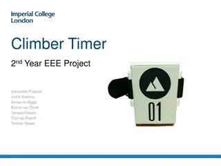
Explore the fundamentals of IO and timer configuration for MSP430 LaunchPad in this lab at National Tsing Hua University, Taiwan. Learn about setting up I/O ports, timers, debugging basics, and sample code implementation for input and output handling.

Download Presentation

Please find below an Image/Link to download the presentation.
The content on the website is provided AS IS for your information and personal use only. It may not be sold, licensed, or shared on other websites without obtaining consent from the author. If you encounter any issues during the download, it is possible that the publisher has removed the file from their server.
You are allowed to download the files provided on this website for personal or commercial use, subject to the condition that they are used lawfully. All files are the property of their respective owners.
The content on the website is provided AS IS for your information and personal use only. It may not be sold, licensed, or shared on other websites without obtaining consent from the author.
E N D
Presentation Transcript
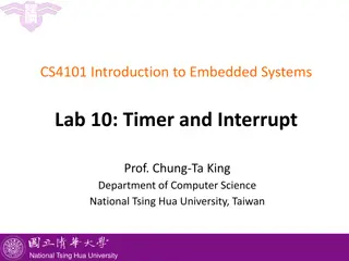
CS4101 Introduction to Embedded Systems Lab 2: Basic IO and Timer Prof. Chung-Ta King Department of Computer Science National Tsing Hua University, Taiwan National Tsing Hua University
Introduction In this lab, we will learn the basic IO and timer of MSP430 LanuchPad Configure the I/O port of LanuchPad for input Set the timer Run the debugger for basic debugging 1 National Tsing Hua University
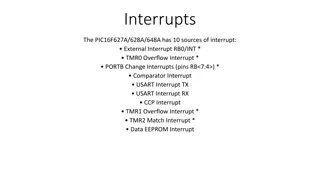
Interior of MSP430G2553 X Not available on 20-pin device 2 National Tsing Hua University
PxDIR (Pin Direction): Input or Output P1IN.7 P1OUT.7 P1DIR.7 1 7 6 5 4 3 2 1 0 P1IN P1OUT P1DIR PxDIR.y: 0 = input 1 = output Register example: P1DIR &= 0x81; 1 1 3 National Tsing Hua University
GPIO Output P1IN.7 P1OUT.7 P1DIR.7 1 1 1 7 6 5 4 3 2 1 0 P1IN X P1OUT 1 P1DIR PxOUT.y: 0 = low 1 = high Register example: P1OUT &= 0x80; 1 4 National Tsing Hua University
GPIO Input P1IN.7 P1OUT.7 P1DIR.7 P1REN.7 Enable resistor 7 6 5 4 3 2 1 0 x P1IN 1 P1OUT 0 P1DIR 1 P1REN PxREN enables resistors PxOUT selects pull-up (1) or pull-down (0) resistor 5 National Tsing Hua University
Sample Code 1 for Input #include <msp430.h> #define LED1 BIT0 // P1.0 to red LED #define B1 BIT3 // P1.3 to button void main(void){ WDTCTL = WDTPW + WDTHOLD; // Stop watchdog timer P1OUT |= LED1 + B1; P1DIR = LED1; // Set pin with LED1 to output P1REN = B1; // Set pin to use pull-up resistor for(;;){ //Loop forever if((P1IN & B1) == 0){ // Is button down? P1OUT &= ~LED1; } // Turn LED1 off else{ // Button is up P1OUT |= LED1; } // Turn LED1 on } } 6 National Tsing Hua University
Sample Code 2 for Input #include <msp430.h> #define LED1 BIT6 // P1.0 to green LED #define B1 BIT3 // P1.3 to button volatile unsigned int i, j; void main(void){ WDTCTL = WDTPW + WDTHOLD; // Stop watchdog timer P1OUT |= LED1 + B1; P1DIR = LED1; // Set pin with LED1 to output P1REN = B1; // Set pin to use pull-up resistor for(;;){ while((P1IN & B1) != 0){ // Loop on button up i = P1IN; j = P1OUT; } P1OUT &= ~LED1; // Turn LED1 off while((P1IN & B1) == 0){ // Loop on button down i = P1IN; j = P1OUT; } P1OUT |= LED1; // Turn LED1 on } } 7 National Tsing Hua University
Lab 2 Basic 1: Upload and run sample code 1 and 2 on the MSP430 LaunchPad respectively. Do they behave differently? Why? Basic 2: Modify to flash only the red LED when the button is down and flash only the green LED when the button is released. Run the debugger to show the values of P1IN after each while() statement 8 National Tsing Hua University
How to Debug? In the code line containing: i = P1IN; j = P1OUT; Add new expression from Expressions window Right-click on the appropriate line of code and set the Breakpoint When the code runs, it will hit the breakpoint and stop You can now observe the value 9 National Tsing Hua University
Debugger Output 1111 1110 01001000 00000110 00001000 No need to care about other bits! 10 National Tsing Hua University
Interior of MSP430G2553 X Not available on 20-pin device 11 National Tsing Hua University
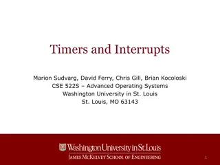
MSP430 Timer0_A3: Registers TA0R (0170h): the counter itself TA0CCR0 (0172h): target for counting TA0CTL (0160h): control settings Others: clock source selection, flags 12 National Tsing Hua University
Inside Timer0_A3 Timer_A Control Register: TA0CTL 13 National Tsing Hua University
Timer0_A3 Control Register (TA0CTL) TASSELx: Timer0_A3 clock source select (x is 0, 1, 2, or 3) IDx: input divider MCx: mode control TACLR: Timer0_A3 clear TAIE: Timer0_A3 interrupt enable TAIFG: Timer0_A3 interrupt flag 14 National Tsing Hua University
TACTL (TA0CTL/TA1CTL) TA0CTL = TASSEL_2 + MC_1; // src from SMCLK, up mode 15 National Tsing Hua University
Timer Mode MCx=00: Stop mode The timer is halted MCx=01: Up mode The timer repeatedly counts from 0 to TACCR0 MCx=10: Continuous mode The timer repeatedly counts from 0 to 0FFFFh MCx=11: Up/down mode The timer repeatedly counts from 0 to TACCR0 and back down to 0 16 National Tsing Hua University
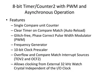
Sample Code 1 for Timer_A Goal: simplest way to flash an LED at 1 Hz Need an event to trigger the flashing counter (TA0R) overflow Need a way to detect the event CPU polling How to make TA0R overflow at 1 Hz? Use SMCLK clock (discussed later) at 800 KHz When TAR (16 bits) overflows, it has counted 216, equivalent to a period of 216/800KHz 0.08 sec Divide the frequency of the clock by 8 to give a period of about 0.64 sec close enough! Continuously count up; on overflow return to 0 17 National Tsing Hua University
Sample Code 1 for Timer_A #include <msp430g2553.h> #define LED1 BIT0 void main(void) { WDTCTL = WDTPW | WDTHOLD; P1DIR = LED1; P1OUT = ~LED1; TA0CTL = MC_2 | ID_3 | TASSEL_2 |TACLR; for(;;) { while(!(TA0CTL & TAIFG)){} TA0CTL &= ~TAIFG; // Clear overflow flag P1OUT ^=LED1; } } 18 National Tsing Hua University
Sample Code 2 for Timer0_A3 Can have more accurate time if we can control the amount to count The maximum desired value of the count is programmed into TA0CCR0 TAR starts from 0 and counts up to the value in TA0CCR0, after which it returns to 0 and sets TAIFG Thus the period is TA0CCR0+1 counts With SMCLK (800KHz) divided down to 100 KHz, we need 50,000 counts for a delay of 0.5 sec store 49,999 in TA0CCR0 19 National Tsing Hua University
Lab 2 Basic 3: Flash the red LED at 1 Hz by polling Timer0_A3. After the button is pressed for more than 3 seconds, flash the green LED at 4 Hz. When the button is released for more than 3 seconds, flash red LED at 1 Hz. If button activity is shorter than 3 seconds, then do nothing. Note two events to monitor: timer up and button down. Bonus: Flash the red LED according to the time you press the button. For example, press the button for 1 second, flash at 1Hz; press for 2 seconds, flash every two seconds (0.5Hz), etc. When press the button for 5 seconds, turn off LED. 20 National Tsing Hua University


: Input or Output")


")
")