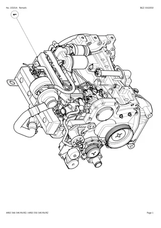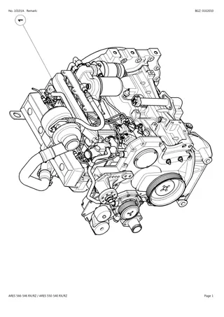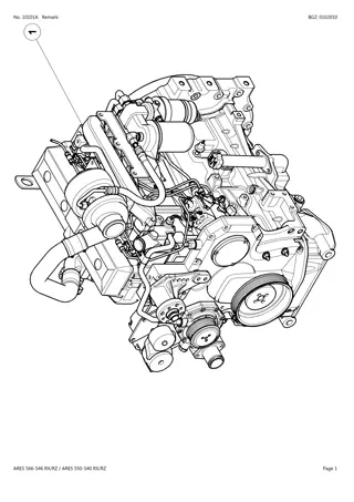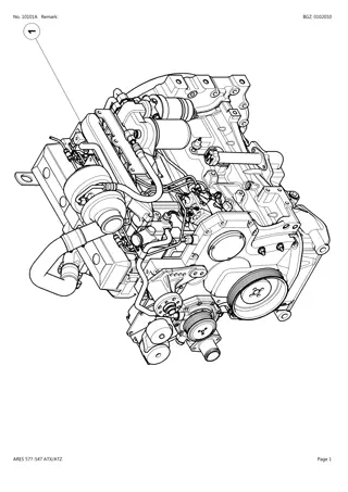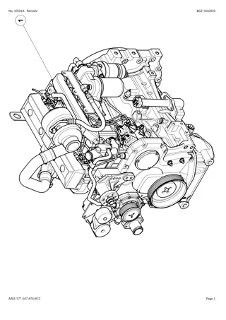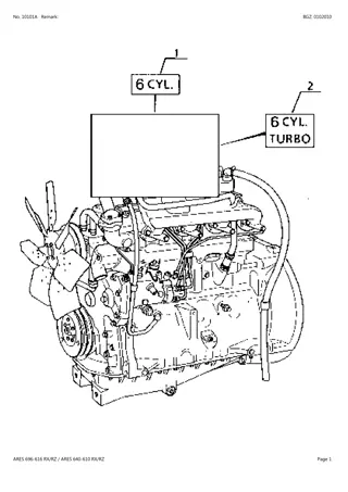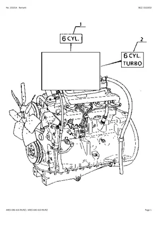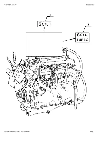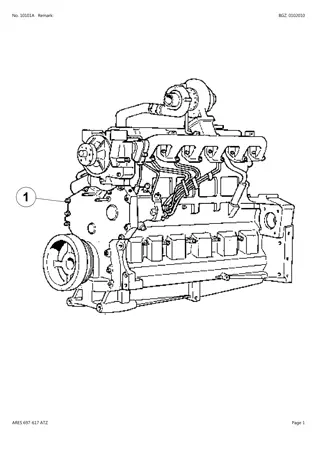
CLAAS ARES 697-617 ATZ (Type A03) Tractor Service Repair Manual Instant Download
Please open the website below to get the complete manualnn//
Download Presentation

Please find below an Image/Link to download the presentation.
The content on the website is provided AS IS for your information and personal use only. It may not be sold, licensed, or shared on other websites without obtaining consent from the author. Download presentation by click this link. If you encounter any issues during the download, it is possible that the publisher has removed the file from their server.
E N D
Presentation Transcript
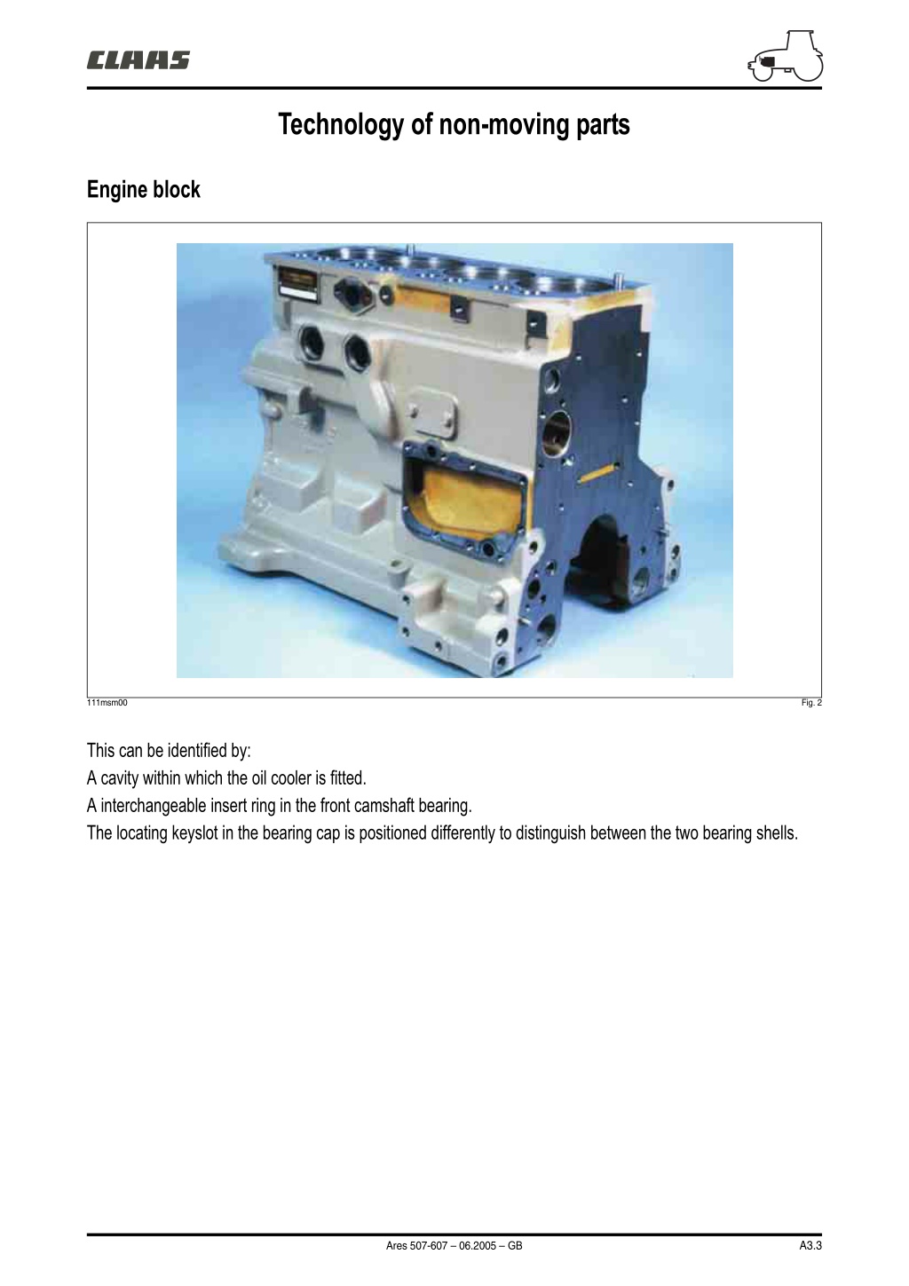
Technology of non-moving parts Engine block 111msm00 Fig. 2 This can be identified by: A cavity within which the oil cooler is fitted. A interchangeable insert ring in the front camshaft bearing. The locating keyslot in the bearing cap is positioned differently to distinguish between the two bearing shells. A3.3 Ares 507-607 06.2005 GB
Technology of non-moving parts Wet liner A The upper flange between the liner and the block incorporates a slope of 0,5. A range of shims are available for setting liner protrusion (A). The base of the liner is located by 3 seals: 1. Square shaped neoprene gasket fitted on the sleeve for sealing. 1 Note: Check location when rebuilding. 2 2. White O-ring, fitted in the block ensuring vibration stability. 3 3. Black O-ring, fitted in the block, ensuring vibration stability. 111msm01 Fig. 3 A3.4 Ares 507-607 06.2005 GB
Technology of non-moving parts Cylinder head H 131msm00 Fig. 4 This can be identified by: The cross-flow design. The intake ducts are designed to increase turbulence inside the cylinders to enhance the air/fuel mix (SWIRL). A cast letter (H) in the inlet port identifies the model of cylinder head. The cylinder head now incorporates a housing for the direct mounting of the thermostat. The cylinder head gasket is specific. It has a compressed graphite film on both surfaces. A3.5 Ares 507-607 06.2005 GB
https://www.ebooklibonline.com Hello dear friend! Thank you very much for reading. Enter the link into your browser. The full manual is available for immediate download. https://www.ebooklibonline.com
Technology of non-moving parts Valves 131msm01 Fig. 5 Nomenclature A Collets. B Valve rotator. C Spring. D Umbrella seal. D C B A 131hsm10 Fig. 6 The valve guides are machined directly in the cylinder head. A helicoidal open groove improves lubrication between the guide and valve. An "umbrella" type seal (D) allows the passage of a controlled quantity of oil to provide lubrication for the valve stem. Each valve is fitted with a rotator (B) ensuring a 3 rotation upon each valve actuation. The contact surface between the valve head and the seat insert is thus always clean. A3.6 Ares 507-607 06.2005 GB
Technology of moving parts Thrust bearings 131hsm00 Fig. 7 The cushions are of the one-piece type. One is smooth, the other has a groove for lubrication. Several sizes are available for the adjustment of crankshaft end float. Crankshaft 121msm01 Fig. 8 A3.7 Ares 507-607 06.2005 GB
Technology of moving parts Pistons Nomenclature 1 Sharp-edged. 2 "Snake head" conrod. 3 Re-entrant bowl (chamber-in-piston). 1 1 3 2 121msm03 Fig. 9 Both the pistons and the connecting rods are specific to this type of engine. The combustion chamber, centered in the piston crown, is of the "re-entrant" type. The latter forms a sharp edge with the piston crown and these features give improved combustion. The marking "front" has to be fitted facing the front of the engine. Connecting rods The "viper head" connecting rod heads improve the piston pin span. Metric threads are used for the conrod bolts. A3.8 Ares 507-607 06.2005 GB
Technology of moving parts Rings 1 1 2 3 A B 3 2 121msm04 Fig. 10 The top compression ring is as close as possible to the top of the piston to reduce waste space. This has necessitated the use of an insert that has better temperature resistance. An accumulation groove between the top compression ring and the compression ring gives the gases a greater expansion volume. The top compression ring thus remains in contact with its bearing surface, reducing the passage of gas to the lower part of the engine. 1. The top compression ring is trapezoid shaped with a contact face of the barrel type. It is marked with a dot (A). 2.The compression ring has a trapezoid cross-section, with a skewed contact face. It is marked with 2 points (B). 3. The oil control ring has a classical shape. A3.9 Ares 507-607 06.2005 GB
Technology of moving parts Accessory gear train 121msm05 Fig. 11 Fuel distribution is powered by a helical toothed gear train. Marks engraved on the pinions indicate meshing positions to obtain fuel distribution settings. A3.10 Ares 507-607 06.2005 GB
Technology of moving parts Balance shaft A A B C 121msm06 Fig. 12 Nomenclature Counterweights. Counter boring. Cotter. A B C The 4 cylinder engine is equipped with with two balance shafts with detachable counterweights (A) to counter vibrations from the rotating components (bushes are also mounted in bores). "Damper" On a 6 cylinder engine, vibration resulting from the crankshaft's torsional response are absorbed by an elastic-hubbed pulley (the crankshaft "Damper"). Nomenclature 1 Pulley. 2 "Damper". 3 Screw. 4 Washer. 3 1 2 4 101msm23 Fig. 13 A3.11 Ares 507-607 06.2005 GB
Lubrication Lubrication system V S Q R M K O F L Z I A Y 221msm00 Fig. 14 A3.12 Ares 507-607 06.2005 GB
Lubrication H G 221msm01 Fig. 15 Nomenclature (Fig. 14 and 15) Oil pump. Oil suction pipe. Oil outlet tube. Oil cooling casing. Coolant passage adaptor. Oil filter. Oil filter manifold/adaptor. Oil filler tube. Oil cooler. Crankshaft oil galleries. Pressure switch. Nozzles. Main lubrication duct. Connecting rod bearings. Camshaft bushes. Gudgeon pin and bush. Rocker shaft. Turbocharger oil supply duct. Rockers. Oil feed. Oil pressure regulator. Oil bypass valve. Pressurized oil. Non pressurized oil. A B C D E F G H I K L M N O Q R S T V X Y Z AA AB A3.13 Ares 507-607 06.2005 GB
Lubrication Oil system components 1 221msm02 Fig. 16 Nomenclature Seal. 1 The oil cooler is an exchanger featuring 7 plates inserted between the oil pump and the filter. It speeds up oil warm-up on engine start thanks to the flow of water from the cylinder head pumped by the water pump. It then regulates and evens out the temperature. It is fitted in a cavity of the cylinder block. A3.14 Ares 507-607 06.2005 GB
Lubrication 221msm03 Fig. 17 In very cold conditions, the by-pass valve is designed to bypass part of the oil directly to the primary gallery, by short-circuiting the filter and cooler for a short time. This valve requires no adjustment or maintenance. 221msm04 Fig. 18 The oil spray nozzles screwed to the galleries provide lubrication to the liners and gudgeon pins as well as cooling for the bases of the pistons, with a flow of around 1,4 l/m. A3.15 Ares 507-607 06.2005 GB
Cooling Cooling system O A D J H E U t G F L t R T I S t M W V X 221msm05 Fig. 19 A3.16 Ares 507-607 06.2005 GB
Cooling 251msm00 Fig. 20 Nomenclature (Fig. 19 and 20) Water pump. Coolant passage adaptor. Oil cooler drain plug. Oil cooler plates. Cooling fluid passage. Cooling fluid envelope. Passages in the upper part of the block. Passages. Thermostat. Water manifold/thermostat housing. Bypass circuit. Towards the radiator upper tank. Drain plug. Water pump suction side. High temperature cooling fluid. Low temperature cooling fluid. Cabin heater valve. Cabin heater radiator. Engine management thermistance. Instrument panel thermistance. Heat exchanger. Expansion tank. Depending on installation. A B C D E F G H I J L M N O P Q R S T U V W X A3.17 Ares 507-607 06.2005 GB
Cooling Components of cooling system The thermostat is incorporated within the cylinder head by means of the water housing. Part of the water flow is diverted to the water pump via a steel tube. The temperature is regulated between 82 and 95 C. Nomenclature A Coolant temperature probe. A 251msm01 Fig. 21 N.B.: During filling, with the engine idling, purge the circuit by loosening the temperature probe (A) (Fig. 22). A 251msm02 Fig. 22 The water pump is fitted in the distribution casing and uses the cavity in the cover as the pump body. 251msm03 Fig. 23 A3.18 Ares 507-607 07.2006 GB
Cooling The viscous clutch has 3 main parts: Drive part = Rotor (1) + Plate (2) fitted with annular grooves. Driven part = Hub (6) for the fan + Body (7) fitted with annular grooves. Regulator part = Thermostatic spring (3) + Valve (4) that controls the flow of coupling fluid. This silicon-based viscous fluid is stored in tank (5). When the temperature of the air flowing through the radiator reaches a predetermined level the thermostatic spring operates the valve which opens the orifice. By centrifugal force, the liquid travels towards the annular grooves in the hub and the body. The torque is transmitted by the internal friction of the highly viscous liquid and its adhesion to the walls. The fan is thus powered and the cooling is improved. Nomenclature 1 Shaft. 2 Plate. 3 Thermostatic spring. 4 Valve. 5 Tank. 6 Hub. 7 Body. 6 2 1 7 5 Warning for the storage of Visco. 4 3 253msm00 Fig. 24 A3.19 Ares 507-607 06.2005 GB
Air Air circulation I J H G t K t F E M C B D A L 141msm00 Fig. 25 A3.20 Ares 507-607 06.2005 GB
Air Nomenclature Filter. Filter blockage thermal switch. Pneumatic compressor. Turbo. Intercooler (depending on assembly). Intercooler blockage thermal switch. Air temperature thermistance. Pre-heat flange. Pre-heat relay. Instrument panel. Intake/exhaust. Dust rebreathing. Exhaust. A B C D E F G H I J K L M Pre-heating Both the pre-heating and the illumination of the instrument panel warning light are controlled by the engine ECU. Dust rebreathing Dust rebreathing is achieved by a duct subject to a venturi effect between the exhaust pipe and the air filter. A3.21 Ares 507-607 06.2005 GB
Suggest: For more complete manuals. Please go to the home page. https://www.ebooklibonline.com If the above button click is invalid. Please download this document first, and then click the above link to download the complete manual. Thank you so much for reading
Tightening torques Front chassis / engine link 1. 35 daN.m. Engine/transmission link 2. 73,5 daN.m + Frenetanch (242). 3. 28 daN.m + Frenetanch (242). 4. Guide pin. 1 1 101msm16 Fig. 26 3 3 4 4 3 3 2 2 Fig. 27 101msm17 A3.22 Ares 507-607 06.2005 GB
Tightening torques 14 daN.m Frenetanch (242) 8 1 daN.m 3 daN.m* 1 x M20 x 80 53 daN.m 8 x M12 x 40 11 daN.m 53 daN.m 1 x M20 x 110 13 daN.m + 45 2 x M16 x 70 101msm01r Fig. 28 * If fitting a heater = 3,4 daN.m. A3.23 Ares 507-607 06.2005 GB
https://www.ebooklibonline.com Hello dear friend! Thank you very much for reading. Enter the link into your browser. The full manual is available for immediate download. https://www.ebooklibonline.com

