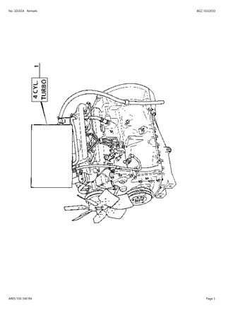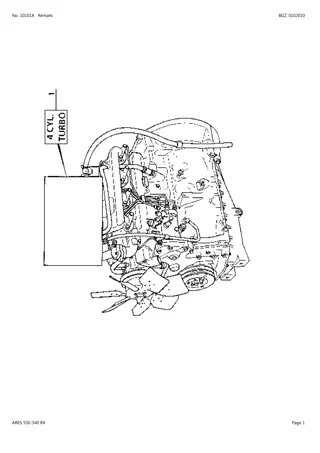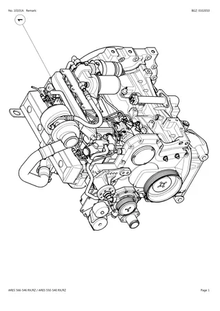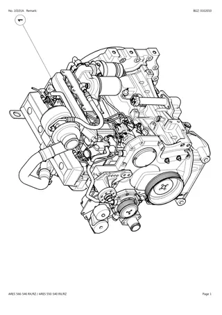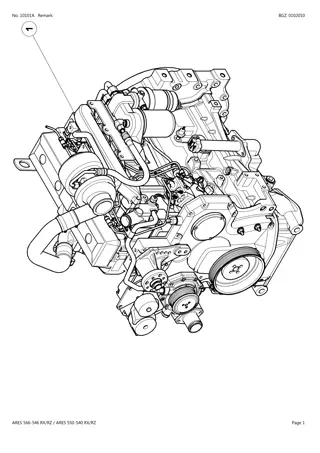
CLAAS ARES 566-546 RX RZ (Type A06) Tractor Service Repair Manual Instant Download
Please open the website below to get the complete manualnn//
Download Presentation

Please find below an Image/Link to download the presentation.
The content on the website is provided AS IS for your information and personal use only. It may not be sold, licensed, or shared on other websites without obtaining consent from the author. Download presentation by click this link. If you encounter any issues during the download, it is possible that the publisher has removed the file from their server.
E N D
Presentation Transcript
REMOVAL/INSTALLATION D1-2.9 MR 332 - 06.2002 - EN 60 05 029 693 - 10.2003 - EN
Removal/installation Preliminary operations Park the tractor on flat, level, firm ground, peferably in the low position. - Apply the hand brake. - Disconnect the battery. - Chock the rear wheels. - Remove the transmission shaft housing. - Drain the oil from the front axle housing and the hubs. - Support the tractor under the crankcase (using axle- stands), with the front axle in the low position. - Remove the front wheels. - Disconnect the unions from the steering hydraulic hoses. To facilitate the operation and tilt the axle. - Remove the supply hose from the differential lock control. - Remove the cover from the suspension position sensors and disconnect the electrical connectors. - Open the front valve to bleed any residual pressure (see page D1-2.26). - Disconnect the unions from the suspension and steering hydraulic hoses. - Using a hoist, the spreader bar 77 01 388 906 and 2 slings, lower the front axle then remove it after removing the 4 attachment bolts from the 2 bearings. Fig. 1 D12-006 Wheel alignment adjustment Max toe-in: 2 mm The adjustment is performed with the wheels fitted on the tractor, on the ground and straight, with the suspension in medium position. The measurementsbetween the wheel rims are made at the height of the wheel horizontal axis, on the edge of the rims, between the two X points. - Apply a marking on these points. - Measurethe dimension A between the X points. - Push the tractor forward to turn the wheels by one half-revolution (front axle declutched) and measure the dimension B (between the same X points). - Adjust the rods on the steering joints uniformingly in order to obtain A = B or A = B + 2 mm max. - Torque tighten the locknuts on the rods to 25 daN.m Safety It is imperative to support the front axle on axle stands as well as the rear axle if the operation to be performed requires the engine to be run, the front axle remains engaged at rest. The tractor may move forward. X = Measurement points between rims Tractor front Rim 1/2 revolution D12-007 Fig. 2 D1-2.10 MR 332 - 06.2002 - EN 60 05 029 693 - 10.2003 - EN
Removal/installation Steering link rods and cylinder Hydraulic control Refer to the chapter E3 STEERING . Description (1) Steering cylinder (2) Caps (3) Adjustment nuts (4) Link rods (Tie rod + joints) Fig. 3 D12-008 Removal/installation - Remove the front LH wheel (if the front axle remains fitted on the tractor). - Extract the steering joints (4). - Remove the cap (2) on the RH side. - Disconnect the hydraulic supply pipes from the cylinder and remove the unions from the cylinder (1). To ease cylinder sliding in the support bores, remove the paint using a Loctite type spray can. - Unscrew the four bolts (C) and remove the cylinder. - The seals must imperatively be replaced. D1-2.11 MR 332 - 06.2002 - EN 60 05 029 693 - 10.2003 - EN
https://www.ebooklibonline.com Hello dear friend! Thank you very much for reading. Enter the link into your browser. The full manual is available for immediate download. https://www.ebooklibonline.com
Removal/installation Planetary reductions and wheel hubs 14 26 27 28 8 9 11 8 7 6 1 13 3 2 4 22 31 25 24 16 15 23 20 21 19 (14) Bolt (7.9 daN.m) (15) Bolt (23 daN.m) (16) Bush (17) Washer (18) Gear (19) Circlip (20) O-ring (21) Tapered bearing (22) Stud (23) Wheel half-hub (24) Tapered bearing (25) Seal (26) Washer (27) Pin (28) Washer (29) Washer (30) Circlip (31) Wheel shaft 18 17 D12-009 29 30 Description (1) Hub cover (2) Plug (6 daN.m) (3) Nut (7 daN.m) (4) Bolt (2,5 daN.m) (6) Planet pins (7) Washers (8) Needles (9) Planet gears (11) Spacer (13) Crown wheel Fig. 4 D1-2.12 MR 332 - 06.2002 - EN 60 05 029 693 - 10.2003 - EN
Removal/installation Planetary reductions - Unscrew the plug (2) in the up position to avoid any discharge due to overpressure. - Drain the oil from the hub after bringing it to the low position. - Unscrew the bolts (4) and remove the cover (1) from the wheel hub using the 2 slots on the periphery. - Check the condition of the O-ring (20) for gearbox sealing. - Check the needles (8) of the stop washer (7) and of the planet spacer (11) for wear. Replace if necessary. - Check the pins (6) on the planet gears (9). If damaged, replace the satellite holder/pin assembly (only one reference). - During installation, make sure the washer (28) is centred. Tightening torques - Cap (23) - Bolts (4) - Bolts (14) - Bolt (15): : 6 daN.m : 2.5 daN.m : 7.9 daN.m : 23 daN.m Wheel hub - Remove the spring clip (30), remove the stop washer (29), as well as the 2 washers (17), fitted on the universal joint shaft (31), replace if necessary. - Unscrew the bolts (15) to remove the wheel hub from the steering joint. - To remove the gear (18) and ring gear (13) assembly, use two bolts (15) as extractors, to be screwed into the threaded holes in the gear (18). - Remove all the centring bushes (16) using a bearing extractor. - Systematically replace the sealing bush (25). Grease it and use tool 60 05 006 535 to install it. - Extract the wheel half-hub (23) and the bearings (21) and (24). Fig. 5 Important: In all cases, before fitting new parts, check the following dimensions: D12-010 A = 17.950 to 18.000 mm B = 64.275 to 64.325 mm C = 21.43 mm D = 23.070 to 23.172 mm Note: Installing wheel hub bearings does not require any specific adjustment for preload or clea- rance. Fig. 6 D12-011 D1-2.13 MR 332 - 06.2002 - EN 60 05 029 693 - 10.2003 - EN
Removal/installation Wheel joints and upper arm Wheel joint (1) LH wheel joint (2) RH wheel joint (3) Upper ball joint (4) Lower ball joint (5) Nut (14 daN.m) (6) Flange (7) Washer (8) Nut (25 daN.m) (9) Flange (10) Bolt (16.9 daN.m) (11) Seal (12) Bush (13) Bush (14) Plug (15) Stud (16) Washer (17) Nut (45 daN.m) 5 3 6 7 8 11 1 12 13 5 14 4 2 9 10 8 17 16 15 21 22 19 18 20 24 25 26 27 33 28 23 29 34 43 35 30 36 44 31 32 25 26 28 34 29 35 36 30 27 42 41 40 D12-017 39 38 37 (35) Bush (36) Seal (37) Bolt (38) Seal (39) Cover (40) Washer (41) Bush (42) Bush (43) Locking bolt (44) Locknut (26) Bush (27) Washer (28) Centring bush (29) Circlip (30) Cap screw (31) Yoke (32) Lower pin (33) Pin (34)Washer Upper arm (18) Upper arm (19) Seal (20) Shaft (21) Washer (22) Bush (23) Seal (24) Upper pin (25) Seal Fig. 7 D1-2.14 MR 332 - 06.2002 - EN 60 05 029 693 - 10.2003 - EN
Removal/installation - Insert the pin of yoke (31). - Lubricate and insert a new combined seal on the centring bush. - Insert the circlip (29) and the cap screw (30) into the yoke joint extraction hole. - Coat with LOCTITE 542 and torque tighten the bolt of the yoke pin of the universal joint guard. Wheel joint Removal - Loosen the nuts (5) and (8) and the locking bolt (43) for the yoke pin of the universal joint guard. - Remove the circlip (29) from the lower pin (32) of the yoke. - Push out the pin (33). - Remove the cap screw (30) and the centring bush (28). - In the centring bush (28) extraction hole, screw in a screw extractor. - Remove the centring bush (26) from the yoke and check the condition of the combined seals (25) and (36), replace if necessary. - Screw a screw extractor into the hole of the lower pin (32). - Check all the components removed and, if damaged, replace them. - Remove the two attachment bolts (16) (Fig. 8) from the lower pin (14) (Fig. 8) on the suspension cylinder and remove it. - Remove the slotted nut (5) from the upper arm using tool 60 05 006 553, the slotted nut (8) from the lower arm using tool 60 05 006 553 and the flange(9). Note: to remove the slotted nuts located inside the wheel joint, use tool 60 05 006 554. - To remove the joint, it is recommended to start from the upper part. Upper arm Removal - Loosen the locknut and the locking bolt for the yoke pin (31) of the universal joint guard. - Remove the circlip (29) from the yoke upper pin, the cap screw (30) and remove the pin (24) from the yoke (31) using a screw extractor or pliers. - Remove the pin (33). - Remove the centring bush (28) from the yoke and check the condition of the lip seals (25) and (36); replace if necessary. - Loosen the nut (43) and remove the locking bolt from the shaft (20). - Remove the three attachment bolts (37) from the shaft. - Remove the lip seal (38). - Remove the cover (39). - Using a bearing extractor, push out the shaft (20). Note: pay attention to the displacement of bushes (41) and (42) that prevent removing the upper shaft. - Before installing the arm, support it. Note: check all the lip seals (38), (23) and (19), as well as the washers (21), replace if necessary. Installation - Replace the bush (12) using tool 60 05 006 549. - Grease and replace the combined seal (11) using tool 60 05 006 550. - Insert the upper flange (6) into the joint, if previously removed. It is recommended to cool it for easier fitting. - Insert the washer on the lower side and torque tighten the new slotted nut to 25 daN.m. - Insert the lower arm swivel joint into the wheel joint - Fit the lower flange (9), torque tighten the new lower arm slotted nut onto the swivel joint to 25 daN.m, then do the same with the upper arm. - Install the suspension cylinder pin, torque tighten the bolts to 9.5 daN.m. Installation - Install the universal joint support yoke (31), if removed, ensuring correct lubrication of the combined seals (36). - Install the upper arm pin. - Tighten the attachment bolt fitted with the locknut (43) to 13.5 daN.m for the bolt and to 7 daN.m for the nut, making sure to correctly reposition the pin groove. Caution: the arm should rotate freely, without rubbing nor obstacle. D1-2.15 MR 332 - 06.2002 - EN 60 05 029 693 - 10.2003 - EN
Removal/installation Suspension cylinder and lower arm 41 42 43 40 44 46 45 30 2829 27 16 26 19202122232425 11 18 12 17 (24) Front flange (25) Bolt (26) Bush (27) Bolt (28) Plug (29) Circlip (30) Cover (31) Rear flange (32) Bolt (33) Nut (34) Torsion bar (35) O-ring (36) Pin (37) Seal (38) Washer (39) Bush (40) Cylinder pin (41) Bolt (42) Nut (43) Bolt (44) Closing plate (45) Nut (46) Bolt 13 36 35 34 39 31 38 26 37 27 (9) Hydraulic union (11) Lower arm (12) Flange (13) Bolt (14) Pin (15) Grease fitting (16) Bolt (17) Seal (18) Bush (19) Bush (20) Washer (21) Seal (22) Nut (23) Seal 32 33 29 30 Description (1) Cylinder (2) Circlip (3) Washer (4) Seal (5) Washer (6) Grease fitting (7) Washer (8) Seal D12-018 Fig. 8 Suspension cylinder - To remove the suspension cylinder, it is recommended to remove the upper arm. - To remove the suspension cylinder lower pin, release the torsion bars (34) by unscrewing the adjustment screw (32) and the 3 attachment bolts (27). Note: use a flat panel work chisel to free the pin (14) when seized. - Use a 3-leg extractor to remove the cylinder from the axle frame upper part. - During installation, pay attention to tightening and orientation of the union (9). D1-2.16 MR 332 - 06.2002 - EN 60 05 029 693 - 10.2003 - EN
Removal/installation Lower arm and torsion bar - Remove the wheels. - Raise the wheel joints until the end of the stroke (low position). - Remove the cover (30) from the rear flange (31). - Mark the torsion bar (34) in relation to the front (24) and rear (31) flanges. - Mark the torsion bar direction. - Mark the front and rear flanges in relation to the axle frame. - Loosen by a few turns the three attachment bolts on the rear flange (31). - Loosen the locknut (33) on the cap screw (32) fitted on the rear flange (31). - Slowly unscrew the cap screw (32), until removing the torsion bar preload. - Remove the circlips (29) from the torsion bars. - Remove the three attachment bolts from the rear flange (31) and remove it. - To remove the front flange (24), screw one of the attachment bolts (27) into the threaded hole intended for that purpose. - Remove the front flange (24) and the bar (34). If required, remove the 2 centring bushes (26) from the front flange. - To remove the lower arm, unscrew the nut (22) using tools 60 05 006 552 and 60 05 006 551. - Push out the arm pin (36). - Checkthe condition of bushes (18), (19), (39), washers (20), (21) and replace if necessary. Fig. 9 D12-019 - Using tool 60 05 006 558, insert on the front side the bush (18) located on the lower arm and on the axle body. Caution: the bush must be perfectly and completely inserted on the axle body. - Screw and torque tighten to 60 daN.m using tools 60 05 006 552 and 60 05 006 551 (Fig. 9). Caution: the arm should rotate freely, without rubbing nor obstacle. - Replace the seal (37), position the front flange in its housing. - Using LOCTITE 542, bond the attachment bolts on the front and rear flanges. - Raise the wheel sides until the end of the stroke. - Position the rear flange in its housing, located on the lower arm, but do not tighten the bolts. Note: pay attention to the positioning of the O- ring (35) when tightening the rear flange. Installation - To install the lower arm, first insert the two bushes (19) and (39) using tool 60 05 006 555. - Replace the lip seals (17) and the stop bush (38) using tool 60 05 006 559 after lubricating them. These must be installed with the springs facing outwards. Note: the stop bush (38) must be positioned with the friction part facing outwards. - Position the lower arm and insert its pin. Note: to insert it more easily, tap the pin head using a soft mallet. D1-2.17 MR 332 - 06.2002 - EN 60 05 029 693 - 10.2003 - EN
Removal/installation Adjustment of the torsion bar preload - Keep the parallelogram at the upper stop (low posi- tion). - Very slightly screw the cap screw (32) (Fig. 8), until it contacts the axle body, to obtain a point 0. - Rotate the rear flange so that it comes to a stop on the securing bolt side (Fig. 10). - Respect markings stamped on the flats of the torsion bar ends (sx = LH torsion bar, dx = RH torsion bar), as well as markings made during disassembly. D12-020 Fig. 10 - On the front flange side, insert the torsion bar fitted with the circlip (Fig. 11), so that it is perfectly engaged in the flanges and abuts the circlip. D12-021 Fig. 11 - To preload the bar, it is necessary to screw the bolt in by 8 turns (Fig. 12). - Finally torque-tighten the front flange bolts to 7 daN.m. - Finally torque-tighten the 3 rear flange attachment bolts to 16.9 daN.m and the locknut to 4.5 daN.m. - Re-install the front and rear flange covers. D12-022 Fig. 12 D1-2.18 MR 332 - 06.2002 - EN 60 05 029 693 - 10.2003 - EN
Removal/installation Universal joint shafts Note: to remove the seals, it is first necessary to remove the wheel joint. Universal joint shaft, wheel side - Once the wheel joint has been removed, the universal joint shaft comes out easily. - Check the shafts and splines. - Replace the spiders (1) if worn or damaged. Universal joint shaft, differential side - Remove the nut and the universal joint locking cap screw on both sides of the axle (Fig. 13). - To freely move out the lower arm, it is necessary to release the torsion bars, and in some cases, to remove the torsion bar. - Pull the universal joint guard out. - During assembly, lubricate and insert the combined seals (12) using tools 60 05 006 560 and 60 05 006 561. Fig. 13 D12-023 8 2 29 1 7 2 1 28 3 9 4 27 5 26 2 6 1 25 24 12 13 Fig. 14 14 17 2 20 10 (14) Bearing (16) Circlip (17) Bolt (18) Universal joint guard (19) Bolt (20) Bolt (21) Nut (22) Bearing (23) Seal (24) Seal (25) O-ring (26) Bush (27) Bearing (28) Circlip (29) Circlip 21 11 16 18 19 (5) Washer (6) Circlip (7) Ball joint (8) Intermediate shaft (9) Differential shaft (10) Intermediate cap (11) Circlip (12) Seal (13) Bush 22 23 D12-024 Description (1) Spider (2) Circlips (3) Wheel shaft (4) Washer D1-2.19 MR 332 - 06.2002 - EN 60 05 029 693 - 10.2003 - EN
Removal/installation Crown whell and pinion - differential Adjustment of the pinion protrusion distance - Install the bevel gear bearings. - Keep the inner cages of these bearings pressurized using tool 60 05 006 540. The bearings must turn when actuated manually. - Fit a bearing half-flange and measure the diameter "D". - Fit the tool 77 01 388 341 on the bottom of the bearings and measure the "Y" dimension, with the tip of the depth gauge resting on the bearing inner cage. - Deduce the dimension "B": B = Y - 50 + (D/2) - On the bevel gear shaft, place the thickness of shims "C" (Fig. 16): C = B - V Note: V is the value marked on the bevel gear. Fig. 15 D12-026 Preload adjustment of the pinion Note: this adjustment is performed on the pinion alone, after fitting the 2 tapered bearings. - Tighten the nut in stages, without exagerating, using tool 60 05 006 536 to a torque "P" comprised between 9.2 and 13.7 daN. - Wind a piece of string around the pinion, on the splined section of the pinion (Fig. 17). - Using dynamometer 77 01 388 008 measure the force required to drive the pinion into rotation (fitted without sealing bush and without cover). Caution: all preloads must be measured without the seal. - Tab the lock nut skirt. Very important: do not tighten the nut all at once. Gently tap on the pinion ends using ahammer to correctly insert the bearings. Imperatively fit a new spacer. Pinion protrusion distance value "V" 9.2 and 13.7 daN. No. of the crown wheel/pinion assembly D12-027 Fig. 16 Fig. 17 D12-028 D1-2.20 MR 332 - 06.2002 - EN 60 05 029 693 - 10.2003 - EN
Removal/installation Crown wheel and pinion - Axle A 86-1 Description (1) Front bearing (2) Bolt (3) Greaser (4) O-ring (5) Bush (6) Bush (7) Bush (8) Bush (9) Seal (10) Nut (11) Washer (12) Bearing (13) Washer (14) Rear bearing (15) Socket (16) Bolt (17) Greaser (18) O-ring (19) Bush (20) Bush (21) Seal (22) Bush (23) Cylinder support (24) Bolt (25) Plug (26) Pin (27) Flange (28) Bolt (29) Socket (30) Spacer (31) Washer (32) Tapered bearing (33) Adjustment shim(s) (34) Bevel gear (35) Crown wheel (36) Bolt (37) Nut (38) Breather (39) Plug (40) Plug (41) Differential housing (42) Tapered bearing (43) Nut (44) Arrestor (45) Bolt (46) Washer (47) Smooth planetary (48) Grooved planetary (49) Adjusting nut (50) Differential half-axes (51) Planets (52) Tapered washers (53) Differential axis (54) Pin (55) Washer 21 19 57 52 15 45 27 47 41 46 63 58 56 50 54 53 55 51 59 13 12 22 62 11 20 44 18 60 14 16 64 17 65 1 39 10 36 4 37 71 38 9 43 40 2 48 3 42 5 37 6 66 67 70 36 7 49 8 68 69 50 32 61 31 23 30 35 23 33 57 34 24 56 35 32 34 55 31 50 33 30 13 51 54 292728 11 12 26 73 25 41 51 22 21 48 10 70 72 45 67 52 D12-025a 66 9 44 Fig. 18a 65 62 4953 Removal/installation -Drain the axle via the plug orifice (25), fill and top up via the plug orifice (40). Note : Replace the breather (38) every 1000 hours. To remove the pinion assembly, it is necessary to remove the whole differential assembly. But maintain it assembled, the time to loosen the bevel gear nut. - Remove the bearing (14) by unscrewing the bolt (16). - Use a 3-leg extractor to remove the bush (22), then (20) and then (19). - Replace if necessary the bushes (20), (19), (5), (6). - Remove the combined seal (9), replace it when installing. - Using tool 60 05 006 536, unscrew and remove the bevel gear nut (10). - When installing, replace the washers (13) and (31) and especially the spacer (30). - Identify the flanges (27) before removing them, so as not to interchange them when installing. - Extract the differential housing and be careful not to interchange the bearing outer cages. 61 47 - Before removing the differential, apply a marking between the casing and the differential cover. - When installing the casing, replace the bolts (63), lock them with Loctite 242 and torque tighten them to 7 daN.m. - Systematically change all seals. - Extract the bevel gear, use a 3-leg extractor to remove the bearing taper (32). Note : the clearance between satellite gear and pinion must range between 0.085 et 0.131. Important: Before installing, adjust according to the following sequence : 1. Pinion protusion distance. 2. Preload of pinion bearings. 3. Gear backlash (pinion/crown wheel) 4. Preload of differential bearings 52 46 71 69 42 68 43 64 63 60 59 58 D12-025 (56) Discs (57) Counterplates (58) Outside O-ring (59) Piston (60) Inside O-ring (61) O-ring (62) Cover (63) Bolt (64) Tapered bearing (65) Seal (66) Washer (67) Bush (68) O-ring (69) Washer (70) Seal (71) Nut (72) Arrestor (73) Bolt Fig. 18b D1-2.21 MR 332 - 06.2002 - EN 60 05 029 693 - 10.2003 - EN
Removal/installation Crown wheel and pinion - Axle A 92-2 / A 92-3 Mark Max dimension Min dimension Acceptable max wear 46 2.73 2.67 56 1,33 1,27 57 1.63 1.57 0.10 mm - 0.15 mm 57 52 45 27 46 48 41 63 56 50 54 53 46 51 57 21 56 19 15 39 1 44 3736 4 38 12 40 2 3 22 11 48 20 5 18 64 3637 6 14 7 16 8 43 17 71 43 42 35 10 41 42 45 56 62 9 44 57 49 48 33 30 13 50 49 D12-045a 23 50 24 23 52 35 51 34 33 34 56 32 31 54 46 32 57 28 31 27 50 29 13 30 26 73 25 53 11 48 12 72 Description (1)Front bearing (2)Bolt (3)Greaser (4)O-ring (5)Bush (6)Bush (7)Bush (8)Bush (9)Seal (10) Nut (11) Washer (12) Bearing (13) Washer (14) Rear bearing (15) Socket (16) Bolt (17) Greaser (18) O-ring (19) Bush (20) Bush (21) Seal (22) Bush (23) Cylinder support (24) Bolt 51 46 21 22 D12-045 10 Fig. 19a 52 9 62 63 (25) Plug (26) Pin (27) Flange (28) Bolt (29) Socket (30) Spacer (31) Washer (32) Tapered bearing (33) Adjustment shim(s) (34) Bevel gear (35) Crown wheel (36) Bolt (37) Nut (38) Breather (39) Plug (40) Plug (41) Differential housing (42) Tapered bearing (43) Nut (44) Arrestor 64 Removal/installation - Drain the axle via the plug orifice (25), fill and top up via the plug orifice (40). Note : replace the breather (38) every 1000 hours. To remove the pinion assembly, it is necessary to remove the whole differential assembly. But maintain it assembled, the time to loosen the bevel gear nut. - Remove the bearing (14) by unscrewing the bolt (16). - Use a 3-leg extractor to remove the bush (22), then (20) and then (19). - Replace if necassary the bushes (20), (19), (5), (6). - Remove the combined seal (9), replace it when installing. - Using tool 60 05 006 536, unscrew and remove the pinion shaft nut (10). - When installing, replace the washers (13) and (31) and especially the spacer (30). - Identify the flanges (27) before removing them, so as not to interchange them when installing. - Before removing the differential, apply a marking between 71 the casing and the differential cover. - When installing the casing, replace the bolts (63), lock them with Loctite 242 and torque tighten them to 7 daN.m. - Extract the differential housing and be careful not to interchange the bearing outer cages. - Systematically replace all seals. - Extract the bevel gear, use a 3-leg extractor to remove the bearing taper (32). Note : the clearance between satellite gear and pinion must range between 0.085 et 0.131. Important: before installing, adjust according to the following sequence : 1. Pinion protusion distance. 2. Preload of pinion bearings. 3. Gear backlash (pinion/crown wheel) 4. Preload of differential bearings (45) Bolt (46) Disc (48) Grooved planetary (49) Adjusting nut (50) Differential half-axes (51) Planets (52) Tapered washers (53) Differential axis (54) Pin (56) Discs (57) Counterplates (62) Cover (63) Bolt (64) Tapered bearing (71) Nut (72) Lock tab (73) Bolt Fig. 19b D1-2.22 MR 332 - 06.2002 - EN 60 05 029 693 - 10.2003 - EN
Removal/installation Backlash adjustment - Fit the flanges (27) paying attention to correctly position the differential lock supply hole. Note: on axle A 92-1, replace the O-ring (68) (Fig. 18). - Check the gear backlash, which should be between 0.18 and 0.23 mm. - Repeat this check on several teeth. Should the values measured be different, place the dial gauge sensor on the tooth with the lowest value. - Tighten the bearing nuts on the differential to the same torque: use tool 60 05 006 534 (+ 60 05 006 581 for axle A 92-1). - Place the dial gauge sensor at 90 with respect to the surface of a pinion tooth. - Adjust the bearing nuts to move the crown wheel towards or away from the bevel gear, starting on the crown wheel side. - Using a plastic hammer, gently tap the bearings to ensure proper fitting. - Adjust the bearing slotted nuts knowing that: if the clearance detected is below the specified tolerance range, screw on the nut on the opposite side of the crown wheel and unscrew the other nut by the same value. if the clearance detected is above the specified tolerance range, screw on the nut on the crown wheel side and unscrew the other nut by the same value. Fig. 20 D12-029 Differential bearing preload - Adjust gear backlash beforehand. - Wind a piece of string around the splines of the bevel gear shaft. - Measure the rotation force "F" for the crown wheel and pinion assembly. - According to the pinion preload "P" previously measured, apply the formula: F = P +9.2 to 10.7 daN. Example: if P = 11 daN, F = 20.2 to 21.7 daN. - Adjust the bearing nuts making sure to keep the backlash previously obtained. Note: do not interchange the bearing nuts. Fig. 21 D12-030 Installation - Proceed in the reverse order of the removal operations, complying with the tightening torques. - Fit the bevel wheel coated with Loctite 270 and torque tighten the bolts to 7 daN.m. - Coat the supporting faces of the differential casing with Loctite 510 sealing compound. - Fit the combined seal (9) (Fig. 18 - 19) using tool 60 05 006 537. Fig. 22 D12-031 D1-2.23 MR 332 - 06.2002 - EN 60 05 029 693 - 10.2003 - EN
Removal/installation - Install the axle and torque tighten the 4 axle attachment bolts to 40 daN.m and the wheels to 38 daN.m. - Check the breather condition (to be replaced every 1,000 hrs). Before putting the front axle back into operation, do not forget to replenish with oil: axle and planet gear reducers. Note: once the axle has been installed on the tractor, it can be tested. With the engine shut down, the axle up, apply the hand brake. With the help of a person on the opposite side, turn if possible the wheels in the forward direction. They should stop after a while. The second test consists in (with the pinion still blocked) releasing the RH wheel and turning the LH wheel in the forward direction. When correctly fitted, the LH wheel rotates freely, without any excessive effort, and the RH wheel rotates in the opposite direction. Fig. 23 D12-012 Suspension position sensor Note: removing the sensor requires a new adjustment. To re-install the sensor, it is necessary to assemble all the other axle parts. - Unscrewthe sensor cover attachment bolts (1). - Disconnect the electrical connector. - Unscrew the sensor support screws, then remove the assembly (2). - Mark the position of the ring holder bush to correctly position the rubber ring (3) in its housing, during reassembly. - When installing the bush, refer to the marks previously made. - If the rubber ring holder bush (3) has been removed, install it after coating its outer part with LOCTITE 542. - Replace the lip seal (4) if necessary. Note: correctly position the rubber ring holder bush. The word "OUTSIDE" should be facing outwards. - insert the rubber ring in its housing, making sure the protruding part fits in the holder bush recess. - Install and connect the sensor. D12-013 Fig. 24 1 2 3 4 D12-014 Fig. 25 D1-2.24 MR 332 - 06.2002 - EN 60 05 029 693 - 10.2003 - EN
HYDRAULIC CHECKS D1-2.25 MR 332 - 06.2002 - EN 60 05 029 693 - 10.2003 - EN
Hydraulic checks Control group Removal Before working on the suspension control group, release the internal pressure by placing the front axle in the disactivated position. The suspension control group accumulators are discharged in a few seconds and the axle goes fully down. - Open the FR valve to remove any residual pressure from the cylinders and the accumulators by loosening the locknut and unscrewing the bolt by 1 turn (beware of dirt). - Disconnect the connectors from solenoid valves SV-L, SV-R, W-V. Then, unscrew the four attachment bolts on the electronic unit and remove it from the block. - Remove the block. - Remove the nuts from the solenoid valve coils. - Remove the solenoid valves and unscrew the block valves. - Unscrew and remove the AV closing valve. LH cylinder solenoid valve SV-L RH cylinder solenoid valve SV-R Hydraulic supply " P " connected to the auxiliary distributors Return to tank " T " connected to the auxiliary distributors " LS " circuit connected to the auxiliary distributors RH cylinder supply Pilot solenoid valve W-V AV valve LH cylinder supply D12-032 Fig. 1 D1-2.26 MR 332 - 06.2002 - EN 60 05 029 693 - 10.2003 - EN
Suggest: For more complete manuals. Please go to the home page. https://www.ebooklibonline.com If the above button click is invalid. Please download this document first, and then click the above link to download the complete manual. Thank you so much for reading
HYDRAULIC CHECKS - Unscrew and remove the accumulators. Note: retain the underlying seal. If required, unscrew and remove the other LS / T / P unions. Note: check the presence of the bearing seal between the electronic unit and the valve block. - Install the electronic unit onto the valve block and secure it with attachment bolts, torque tighten to 6 daN.m. Connect the solenoid valve connectors. Installation If the LS / T / P unions have been replaced, screw all the unions back onto the valve block at the following torques: P: 8 daN.m T: 8 daN.m LS: 5 daN.m Important: no repair is possible on the accumulators. In case of failure, replace the accumultors. The accumulator charging pressure is 35 bar and should be checked once a year. This operation is performed using the 60 05 006 306 tool case. The valves located in the suspension hydraulic unit shall never be disassembled. - Fit two new seals between the accumulators and the valve block. - Install and screw two new accumulators onto the valve block, torque tighten to 20 daN.m. - Lubricate the valves before installation. Torque tighten to 2.5 daNm. - Secure the solenoid valves onto the valves and torque tighten to 0.9 daN.m. SV -L A1 SV -R AV A2 WV 8 daN.m LS P T 8 daN.m 5 daN.m D12-033 Fig. 2 D1-2.27 MR 332 - 06.2002 - EN 60 05 029 693 - 10.2003 - EN
Hydraulic checks Accumulator charging Note: Accumulator charging is performed using the 60 05 006 306 case, after repair and before putting into operation. - Fit the pressure gauge onto the tool shown in Fig. 3. - Use a TOM POUSS cylinder. - Fit the G3 adapter shown in Fig. 3 onto the cylinder. Note: do not forget the seal. - Fit the hose onto the G3 adapter. - Fit the hose onto the pressure gauge. - Unlock the bleed screw using a 6-point wrench. - Open the gas valve. - Open the cylinder and charge at 35 bar. Note: to increase the life, check the charging pres- sure every 6 months. Fig. 3 D12-034 1 : Gas valve opening. 2 : Hose connector. 3 : Accumulator gas valve. 4 : Pressure release screw. Fig. 4 D12-035 D1-2.28 MR 332 - 06.2002 - EN 60 05 029 693 - 10.2003 - EN
https://www.ebooklibonline.com Hello dear friend! Thank you very much for reading. Enter the link into your browser. The full manual is available for immediate download. https://www.ebooklibonline.com


