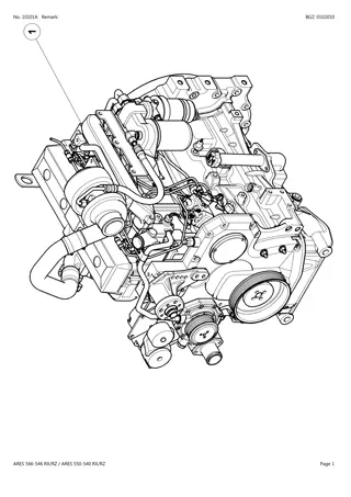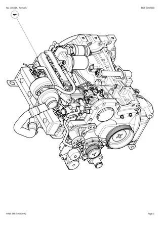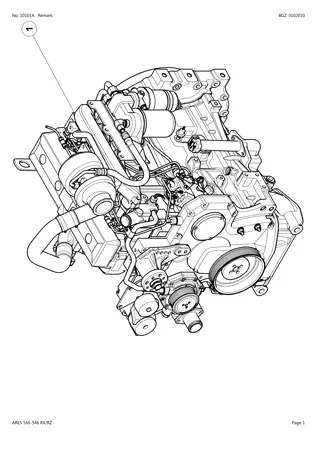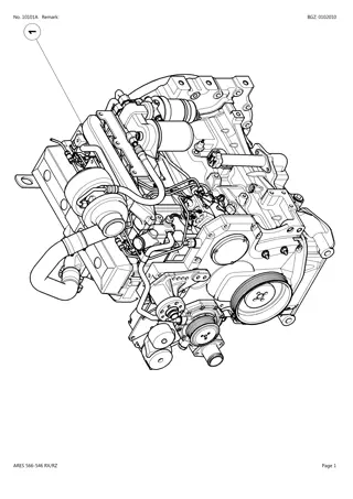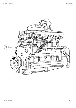
CLAAS ARES 696-616 RZ RC RX (Type A04) Tractor Service Repair Manual Instant Download
Please open the website below to get the complete manualnn//
Download Presentation

Please find below an Image/Link to download the presentation.
The content on the website is provided AS IS for your information and personal use only. It may not be sold, licensed, or shared on other websites without obtaining consent from the author. Download presentation by click this link. If you encounter any issues during the download, it is possible that the publisher has removed the file from their server.
E N D
Presentation Transcript
PRIMARY SHAFT B1.49 MR 332 - 06.2002 - EN 60 05 029 693 - 10.2003 - EN
Primary shaft General presentation The primary shaft and its pinions form the upper line of the gearbox. The primary shaft supports the 1st, 2nd, 3rd and 4th gear driven pinions. The rear teeth is in constant mesh with the Turtle pinion. The shaft front is supported by the tapered bearing at the rear of the input housing and by the bearing fitted in the housing rear bearing assembly. The 1st and 4th gear pinions are maintained in position by 2 spacers. The axial clearance of the pinions is achieved by the fitting of the shims between the 1st and 2nd gear pinions. Removal/installation of the primary shaft Step 7 Fig. 1 B1-013 Preliminary operations To properly shim the bearings when replacing the primary shaft, it is required to remove the gearbox. MR 332 - 06.2002 - EN 60 05 029 693 - 10.2003 - EN B1.50
Primary shaft B1-079 Fig. 2 Description (9) 4th gear pinion (10) Spacer (11) 1stgear pinion (12) Shims (13) 2nd gear pinion (14) Circlip (15) Inner cage bearing (16) Cup bearing (1) Needle bearing (2) Primary shaft (3) Inner cage bearing (4) Cup bearing (5) Shims (6) Deflector (7) 3rd gear pinion (8) Spacer B1.51 MR 332 - 06.2002 - EN 60 05 029 693 - 10.2003 - EN
https://www.ebooklibonline.com Hello dear friend! Thank you very much for reading. Enter the link into your browser. The full manual is available for immediate download. https://www.ebooklibonline.com
Primary shaft Removal - Remove the deflector, the shims and the cup. Extract the assembled shaft (Fig. 3). - Extract the bearing cones. Note: couple the cones and the cups in case of reuse. - Remove the circlip. - Remove the 2nd gear pinion, the shims, the 1st gear pinion and the spacer. - Remove the 4th and 3rdgear pinion. - Extract the needle bearing and discard it. Installation - Clean and inspect the parts, replace all faulty parts. - Fit the needle bearing in contact on the shaft shoulder using a press. Note: after fitting, make sure that the needle normaly turn in the cage. - Install the 3rd gear pinion and the 4th gear pinion. - Slide the spacer. Fit the 1st gear pinion and the 2nd gear pinion. - Fit the circlip - Using a set of feeler gauges, measure the space between the 1st gear pinion and the 2nd gear pinion. Depending on the measure, determine a a thickness of shims to obtain a clearance(Fig. 4) : J1 = 0 to 0.25 mm. - Remove the circlip and the pinion. - Slide the previously selected shims on the shaft . Fit the pinion and the circlip. - Fit the cones to the press using an appropriate fitting. - Install the assembled shaft and the cup. Note: As it is not required to adjust again the bearings when replacing the pinions, the disassembling of the primary shaft can be performed without removing the gearbox of the rear axle according to the following method. Fig. 3 B1-080 J1 = 0/0.25 Fig. 4 B1-081 Removal - Remove the 1st - 2nd gear synchroniser lock and position the lock in order to release the fork. - Remove the lubrication tube and the spring. Loosen the nut. To facilitate the disengaging of the 1st gear pinion to remove the assembled shaft, advance the input pinion fitted with its bearing, the 1st - 2nd gear pinion and the synchro. - Remove the pinions. Installation - Perform the removal operations in the reverse order. - Replace the nut. - Torque tighten the nut of the synchroniser lock to 25 to -30 daN.m. - Check the axial clearance of the 1st - 2nd gear pinions and the synchro operation. MR 332 - 06.2002 - EN 60 05 029 693 - 10.2003 - EN B1.52
Primary shaft Installation of the input housing and adjustment of the primary shaft - Input housing installation. - Chock the primary shaft (Fig. 5) to obtain a clea- rance: J2 = 0.04 / 0.12 mm (Fig. 6). - Fit the locally manufactured tool in the primary shaft (Fig.7). - Slightly compress the spring tightening the nut of the tool in order to properly seat the cones in the cups. - Slightly rotate the shaft. - Using a depth gauge, measure the dimension X between the face A of the cup and the face B of the casing (Fig. 6). - Measure the thickness Y of the deflector. - Calculate the difference between X and Y . - Dtermine the required thickness of shims to achieve J2. - Remove the compression tool. - Position the previously selected shims. - Fit the deflector in the casing. - Install the selection cover. Install the power take off shaft (with the big shoulder in the front) Note: do not forget to position the screw on the casing before installing the cover. - Couple the gearbox to the engine. - Couple the tractor between the gearbox and the rear axle. - Check : - the sealing of the circuits, - the operation of the electric circuits. - Road test of all the controls. - Check the sealing of the unions and seal faces (selection cover, gearbox on the rear axle). Fig. 5 B1-082 B1-083 Fig. 6 Fig. 7 B1-084 B1.53 MR 332 - 06.2002 - EN 60 05 029 693 - 10.2003 - EN
Primary shaft Personal notes: MR 332 - 06.2002 - EN 60 05 029 693 - 10.2003 - EN B1.54
REAR INTERMEDIATE SHAFT B1.55 60 05 029 693 - 10.2003 - EN
Rear intermediate shaft General presentation The output shaft transmits the movement provided by the different gear ratios to the gear shaft of the rear axle. It is fitted on the transmission lower line at the rear of the housing. At the front it is supported by a needle bearing centred in the bore of the front intermediate shaft, and at the rear by two tapered bearings fitted opposite each other. The rear intermediate shaft supports: - the 3rd gear driving pinion, mounted free on the combined bearings. - The 4th gear and range pinion assembly, mounted free. - the Hare/Turtle synchroniser splined integral in rotation. Removal/installation of the rear intermediate shaft Step 8 Fig. 1 B1-014 B1.56 60 05 029 693 - 10.2003 - EN
Rear intermediate shaft To ensure a proper operation of the assembly depending on the efforts undergone by the transmission, several adjustments are required: - J3 adjustment: using the adjusting shim(s): it makes it possible to suppress the clearance of the bearings at the rear of the shaft. - J4 adjustment: the adjustment shim(s) positioned between the shaft shoulder and the bearing enable(s) an axial clearance of the 3rd gear driving pinion. B1-086 Fig. 2 Description (1) Needle cage (2) Rear intermediate shaft (3) Circlip (4) Cup (5) Bearing (6) Bearing (7) Cup (8) Circlip (9) Screw (10) Stop plate (11) Thickness shims (12) Adjustment shims (13) Adjustment shims (14) "Hare" pinion (15) Needle thrust bearing (16) Circlip (17) "Turtle" pinion (18) Bush (19) Dog clutch (20) Synchro rings (21) Double cone (22) Full synchro (23) Synchro rings (24) Double cone (25) Dog clutch (26) Needle cage (27) Cone (28) Needle cage (29) Needle thrust bearing (30) Synchro rings B1.57 60 05 029 693 - 10.2003 - EN
Rear intermediate shaft Remove the output shaft Remove the crawler speed housing (A), if fitted. - Remove the 3 screws. - Remove the stop plate. - Remove the bearing cup. Note: couple the cones and the cups in case of reuse. - Remove the circlip. - Remove the thickness shim and the adjustment shims. - Remove the bearing cone. - Remove the cone. - Remove the adjustment shims. - Pull the shaft backwards. - Remove the shaft. - Through the opening of the selection cover, extract the synchro, the synchro rings, the Hare pinion with the cones, the ring, the two stop washers and the Turtle pinion. Note: couple the synchro rings with the cones. Identify the installation direction of the synchro. Fig. 3 B1-087 - Remove the cup and the circlip. - Remove the needle bearing. B1.58 60 05 029 693 - 10.2003 - EN
Rear intermediate shaft Installation and adjustment of the rear intermediate shaft - Clean and inspect the parts, replace all faulty parts. - Position the circlipand the cup. - On the shaft, install the needle bearing, the washer and the circlip. Engage the shaft in the casing with the pinions and hub without the sliding gears and without the double-cone rings. - Slide the bearings on the shaft. J3 adjustment: - This operation aims at preparing the J3 adjustment. Keep the bearings in contact on the shaft shoulder applying them a manual pressure. - Fill in the Y space (Fig. 4) between the rear of the bearing cone and the circlip groove with the shims and the thickness shim. Choose a new circlip so that it enters sligtly firm in the groove (Fig.6). - Perform the adjustment (Fig. 5) to achieve: J3 = 0.05 preload to 0.05 clearance. The adjustment consists in suppressing the clea- rance between the bearings observing the adjustment tolerance indicated above. If the number of shims in Y does not enable to achieve the proper J3 adjustment, it is possible to adapt the adjustment with the circlip (rectified circlip with different thicknesses to make up for the shim thicknesses). - Fit the circlip Note: position the thickness shim on the circlip side. - Fit the cup and the stop plate. - Torque tighten the screws to 2.7 to -3.2 daNm. Fig. 4 B1-088 Fig. 5 B1-089 Fig. 6 B1-090 B1.59 60 05 029 693 - 10.2003 - EN
Rear intermediate shaft - Position the plunger of the dial gauge at the end of the shaft (Fig. 7). Note: for the housing fitted with crawler speeds, use the housing plate (Fig. 10) to replace the stop plate. Torque tighten the screws to 34 to -52 daNm. - Pull the shaft turning it alternately clockwise and anticlockwise in order to properly "seat" the cones in the cups. - Set the dial gauge to zero and repeat the operation by pulling. - If the read axial clearance exceeds 0.05 mm, determine a shim thickness X to achieve J3 (0.05 preload to 0.05 clearance). J4 adjustment The adjustment consists in achieving an axial clea- rance on the pinion of 0.20 to 0.40. - Position the dial gauge in order ro measure the J4 clearance before adjustment. Read the Y value = 0.50 mm. Determine the number of shims to insert between the shaft and th bearing in (A). Perform the operation: Y 0.30 = 0.50 0.30 = 0.20 mm (0.30 is the average from 0.20 to 0.40). Extract the X thickness, 0.20 mm of shims then remove the shaft and the pinions to perform the proper installation of the pinions and sliding gears with the double-cone synchro assembly. NOTE: perform a "blank" adjustment of the shaft without the sliding gear or the double-cone rings. For the final installation, place the range pinion against the casing as shown on the view. Set the circlip aside with the bearing cage. After passing the assembly, push the shaft. IMPORTANT: first adjust the primary shaft before adjusting the rear intermediate shaft. Fig. 7 B1-091 Fig. 8 B1-092 Y = J4 before adjustment After adjustment 0.20 to 0.40 X Thick. shims B1-093 Fig. 10 Fig. 9 B1-094 B1.60 60 05 029 693 - 10.2003 - EN
FRONT INTERMEDIATE SHAFT B1.61 60 05 029 693 - 10.2003 - EN
Front intermediate shaft General presentation The transmitter shaft is fitted on the two taper roller bearings located in the two lower bearing assemblies of the main housing. At the front, it receives the input pinion. Between the two lower bearing assemblies, it supports the 1st and 2nd gear driving pinions ,mounted free, as well as the 1st, 2nd gear synchroniser assembly whose hub is splined integral. At the rear, it supports the 4th gear driving pinion and the 3rd - 4thgear synchroniser assembly. The rear bore has a needle bearing supporting the front end of the output shaft. The lubrication of the rotating parts is ensured by a central duct and radial holes. The tapered bearings are fitted with preload achieved by the adjustment shims positionned between the washers. Removal/installation of the front intermediate shaft Step 9 Fig. 1 B1-015 Preliminary operations To remove the transmitter shaft, it is required to remove the gearbox. - Disconnect the tractor between the gearbox and the rear axle. - Disconnect the gearbox from the engine. - Remove the selection cover. - Disassemble the guide rod and the forks. - Remove the input housing assembly. - Remove the primary shaft. - Remove the rear intermediate shaft. B1.62 60 05 029 693 - 10.2003 - EN
Front intermediate shaft B1-096 Fig. 2 Description (17) Double-cone synchro rings (18) Dog clutch (19) 1st gear pinion (20) Circlip (21) Cup (22) Bearing (23) Circlip (24) Full synchro (25) Double-cone synchro rings (26) Double-cone synchro rings (27) Dog clutch (28) 3rd gear pinion (29) Front intermediate shaft (30) Spring (31) Clip (32) Lubrication tube (1) Nut (2) Input pinion (3) Bearing (4) Cup (5) Washer (6) Adjustment shims (7) Adjustment shims (8) Circlip (9) Sliding gear (10) Double-cone synchro rings (11) Double-cone synchro rings (12) Dog clutch (13) 2nd gear pinion (14) Bush (15) Washer (16) Double-cone synchro rings B1.63 60 05 029 693 - 10.2003 - EN
Front intermediate shaft Removal/installation and reassembly of the front intermediate shaft Disassembly - Remove the circlip. - Remove the 3rd - 4th gear synchro. Identify the installation direction. - Remove the synchro rings (21). - Remove the pinion (18). Note: couple the ring and the synchro cone in case of reuse. - Position the locking tool Ref. 60 05 006 141 (Fig. 3) and the retaining sleeve, locally manufactured, of the transmitter shaft(Fig. 4). - Remove the lubrication tube and the spring. - Unlock the nut and loosen it using the socket Ref. 60 05 006 140 (Fig. 5). - Remove the input pinion and the cone. - Remove the washers and the shims. - Remove the tool and the sleeve (Fig. 4 and 5). - Extract the shaft from the casing backwards maintaining the 1st and 2ndgearing assembly. Remove in sequence inside the casing: the 2nd gear pinion with the bush, the cone, the 2ndgear synchro rings, the 1st, 2nd gear synchro, the 1st gear synchro rings, the cone, the 1st gear pinion. - Extract the cups. Note: couple the cups and the cones in case of reuse. - Measure the thickness of the adjustment shims to adjust the transmitter shaft during the installation operations. - Remove the cone and the clip. Fig. 3 B1-097 B1-098 Fig. 4 Fig. 5 B1-099 B1.64 60 05 029 693 - 10.2003 - EN
Front intermediate shaft Installation - Clean the casing and the seal faces. - Using a compressed air jet, check that all the ducts of the gearbox and of the shaft are not obstructed. Clean and inspect all parts, replace all faulty parts. - Lubricate the cones, the cups, the bearing bores, the bush. - Fit with the press the bearing cone on the shaft. - Fit the clip. - Position the outer cage in the casing. - Increase of about 0.3 mm the thickness of the shims measured when removing, in order to achieve an axial clearance. - Fit the outer cage. - In the casing assemble in sequence the 1st gear pinion, the cones, the 1st/2nd gear synchro , the synchro rings, the conesand the 2nd gear pinion with the bush and the shims. - Engage the shaft at the rear of the casing maintaining the pinions/synchro assembly (Fig. 6). Note: check that the bush is properly fitted in the pinion. - Fit the locking tool and the retaining sleeve (Fig.3 and 4). - Fit the washers. - Fit the cone on the pinion. - Fit the pinion on the shaft. - Screw on the nut using the socket. Torque tighten to 13 -17 daNm (Fig. 7). - Chock the shaft. Remove the unlocking tool and the sleeve (Fig. 3 and 4). B1-100 Fig. 6 Fig. 7 B1-101 B1.65 60 05 029 693 - 10.2003 - EN
Front intermediate shaft - Position the plunger of the dial gauge at the end of the shaft (Fig. 8). - Through the front of the casing, pull the shaft turning it alternately clockwise and anticlockwise in order to properly seat the cones in the cups. Set the dial gauge to zero. - Repeat the operation by pushing on the shaft. - Depending on the X clearance read, select the required thickness of shims to achieve a preload: P1 = 0.14 / 0.20, a) X + 0.14 if same bearing, b) X + 0.20 if new bearing. - Fit the locking tool and the retaining sleeve (Fig.3 and 4). - Unlock the nut. Remove the pinion. - Extract the cup. - Position the appropriate adjustment shims. - Install the cup and the pinion. - Degrease the thread of the shaft with a solvent. - Slightly coat the nut with Loctite FREINFILET then torque tighten to 13 - 17 daNm. - Lock the nut by deforming the flange in the groove using an appropriate drift punch. - Introduce the spring and the lubrication tube in the shaft. - Remove the locking tool and the retaining sleeve. - Fit the pinionand the synchro cone, the ring and the 3rd and 4th gear synchro. - Install the circlip. Note: pay attention to the installation direction of the synchro. - Manually check: a) the axial clearance of the pinions, b) the rotation of the shaft and its gearing. - Check that the 1st - 2nd gear synchro operates normally. Fig. 8 B1-102 Final operations - Install and chock the front intermediate shaft. - Install the rear intermediate shaft. - Install the input housing assembly. - Chock the rear intermediate shaft. - Install the forks and the guide rod. - Adjust the reverser selector. - Install the selection cover. Note: do not forget to position the screw on the casing. IMPORTANT: first adjust the front intermediate shaft and then adjust the rear intermediate shaft. B1.66 60 05 029 693 - 10.2003 - EN 60 05 029 693 - 10.2003 - EN 60 05 029 693 - 10.2003 - EN
RIGHT COVER AND FORKS B1.67 60 05 029 693 - 10.2003 - EN
Right cover and forks Operating principles The mechanically-controlled selection cover, fitted on the right cover of the gearbox casing has a lever which is used only to select the four basic speeds. B Gearbox lever 1st - 2ndgear selection (A) As the gearbox lever is pushed, the finger is engaged in the 1st - 2nd gear fork inside the grid which prevents the 3rd - 4th gear fork from displacing. The 1stgear ratio is achieved by displacing the lever forwards according to (A) and the 2nd gear ratio backwards. 2 4 A 1 3 3rd - 4th gear selection (A and B) By pushing the gearbox lever to the right, the integral finger of the lever is engaged in the 3rd - 4th gear fork outside the grid preventing the 1st -2nd gear fork from moving. Displacement according to (A) and (B) The 3rd gear ratio is achieved by displacing the lever forwards and the 4th gear ratio backwards. Fig. 1 B1-103 V To shift the 4 mechanical gears, the fork displacement is also limited by the range locking cam (V). B1-104 Fig. 2 Hare/Turtle function (C) The Hare/Turtle position is performed with the gearbox lever in neutral position and a press on the range contactor. The (C) contactor is located on the gearshift lever knob which controls the "Hare/Turtle" solenoid valve through the DRIVETRONIC. B1-105 Fig. 3 B1.68 60 05 029 693 - 10.2003 - EN
Suggest: For more complete manuals. Please go to the home page. https://www.ebooklibonline.com If the above button click is invalid. Please download this document first, and then click the above link to download the complete manual. Thank you so much for reading
Right cover and forks Hare position The E solenoid valve (Fig. 4), fitted on the lower part of the right cover (rear axle) opens and supplies the chamber (a) located at the rear of the piston (Fig. 6). The piston is moving forwards and pushes the fork. The oil contained in the chamber (b) is pumped up in the Turtle duct and returns to the 17-bar circuit. Turtle position A new prompting of the contactor on the gearbox lever contactor triggers the closing of the solenoid valve and a pressure drop in the chamber (a) (Fig. 6). The piston is pushed back under the 17-bar pressure action prevailing on the annular face. The oil contained in the chamber (a) returns to the casing through the hare duct and the duct of the solenoid valve E (Fig. 4). Fig. 4 B1-106 Hare/Turtle lock (Fig. 5) The new system preventing from shifting gears at the same time as changing range makes it possible to avoid the simultaneous displacement of the slider driven by the range fork and of the gearbox which is then locked at the neutral point by means of the cam. Fig. 5 B1-107 b a B1-108 Fig. 6 B1.69 60 05 029 693 - 10.2003 - EN
Right cover and forks Tightening torques of the screws on the cover (in daNm) Loctite Frenetanch 1.5 - 2.5 5 - 7 2.5 - 3.5 Loctite Frenetanch 2.9 - 3.7 Loctite Freinfilet 2.9 - 3.7 Loctite Freinfilet Fig. 7 B1-109 B1.70 60 05 029 693 - 10.2003 - EN
https://www.ebooklibonline.com Hello dear friend! Thank you very much for reading. Enter the link into your browser. The full manual is available for immediate download. https://www.ebooklibonline.com


