Caterpillar Cat D6T XW TRACK-TYPE TRACTOR (Prefix RCW) Service Repair Manual Instant Download
Please open the website below to get the complete manualnn//

Download Presentation

Please find below an Image/Link to download the presentation.
The content on the website is provided AS IS for your information and personal use only. It may not be sold, licensed, or shared on other websites without obtaining consent from the author. Download presentation by click this link. If you encounter any issues during the download, it is possible that the publisher has removed the file from their server.
E N D
Presentation Transcript
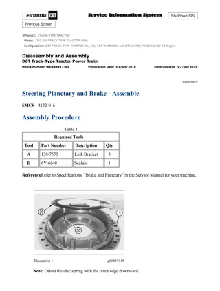
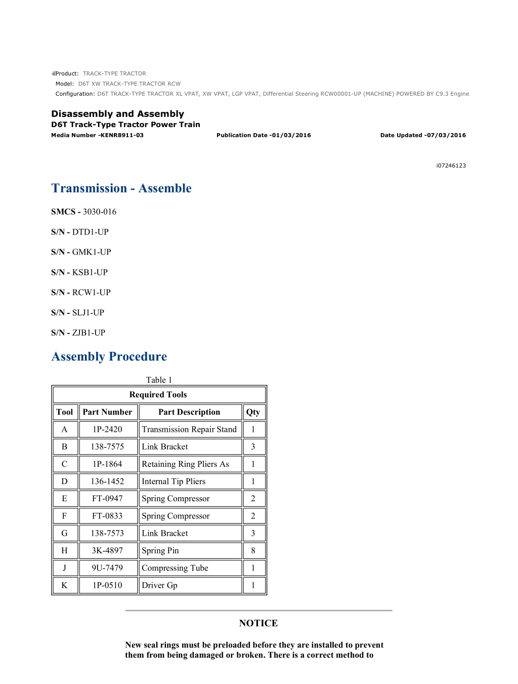
D6T TRACK-TYPE TRACTOR XL VPAT, XW VPAT, LGP VPAT, Differential Ste... 1/19 Product: TRACK-TYPE TRACTOR Model: D6T XW TRACK-TYPE TRACTOR RCW Configuration: D6T TRACK-TYPE TRACTOR XL VPAT, XW VPAT, LGP VPAT, Differential Steering RCW00001-UP (MACHINE) POWERED BY C9.3 Engine Disassembly and Assembly D6T Track-Type Tractor Power Train Media Number -KENR8911-03 Publication Date -01/03/2016 Date Updated -07/03/2016 i07246123 Transmission - Assemble SMCS - 3030-016 S/N - DTD1-UP S/N - GMK1-UP S/N - KSB1-UP S/N - RCW1-UP S/N - SLJ1-UP S/N - ZJB1-UP Assembly Procedure Table 1 Required Tools Tool Part Number Part Description Qty A 1P-2420 Transmission Repair Stand 1 B 138-7575 Link Bracket 3 C 1P-1864 Retaining Ring Pliers As 1 D 136-1452 Internal Tip Pliers 1 E FT-0947 Spring Compressor 2 F FT-0833 Spring Compressor 2 G 138-7573 Link Bracket 3 H 3K-4897 Spring Pin 8 J 9U-7479 Compressing Tube 1 K 1P-0510 Driver Gp 1 NOTICE New seal rings must be preloaded before they are installed to prevent them from being damaged or broken. There is a correct method to https://127.0.0.1/sisweb/sisweb/techdoc/techdoc_print_page.jsp?returnurl=/sis... 2021/8/25
D6T TRACK-TYPE TRACTOR XL VPAT, XW VPAT, LGP VPAT, Differential Ste... 2/19 preload new seal rings prior to installation. Place your hands on each end of the seal ring, and pull (wind) the ends several inches past each other or until they almost make contact. Use care to keep the ring shaped like a circle. This will make an even bend (or ring "set") all around the ring. When the seal ring is in the groove of the hub, the ends must butt together lightly. Do not bend the seal ring. This does not make an even bend all the way around the ring. Do not attempt to use this method to preload a used seal ring. Also, do not use this procedure for cast iron seal rings. This will cause used or cast iron seal rings to break. Note: The friction discs and the clutch plates from the individual clutches must be kept in the correct order. The friction discs and the clutch plates must be kept with the original clutch housings. The different clutches use different friction material. The friction discs and the clutch plates must not bemixedtogether. Note: Lubricate the seals with the lubricant that is being sealed prior to installation. Illustration 1 g02174043 1. Install O-ring seals (142) and (141) to input shaft (110). Illustration 2 g02174027 2. Position washers (133) and (137), planetary gear (136), and bearing (135) into planetary carrier (132). Install planetary shaft (134) into planetary carrier (132). Align the holes in planetary shaft (134) with the hole in planetary carrier (132). Push pin (138) into planetary shaft (134). Repeat for the remaining planetary shafts. https://127.0.0.1/sisweb/sisweb/techdoc/techdoc_print_page.jsp?returnurl=/sis... 2021/8/25
D6T TRACK-TYPE TRACTOR XL VPAT, XW VPAT, LGP VPAT, Differential Ste... 3/19 3. Install bearing (140) into planetary carrier (132). Use Tooling (D) to install retaining ring (139) to planetary carrier (132). Illustration 3 g02173600 4. Install planetary carrier (132) onto input shaft (110). Illustration 4 g02173578 5. Position washers (120), (123), (126), and (129) into planetary carrier (111). Position planetary gears (122) and (127), and bearings (121) and (128) into planetary carrier (111). Install planetary shaft (125) into planetary carrier (111). Align the holes in planetary shaft (124) with the hole in planetary carrier (111). Install pin (125) into planetary shaft (124). Repeat for the remaining planetary shafts. 6. Install bearing (130) into planetary carrier (111). Use Tooling (D) to install retaining ring (131) into planetary carrier (111). Illustration 5 g02173491 https://127.0.0.1/sisweb/sisweb/techdoc/techdoc_print_page.jsp?returnurl=/sis... 2021/8/25
https://www.ebooklibonline.com Hello dear friend! Thank you very much for reading. Enter the link into your browser. The full manual is available for immediate download. https://www.ebooklibonline.com
D6T TRACK-TYPE TRACTOR XL VPAT, XW VPAT, LGP VPAT, Differential Ste... 4/19 7. Install O-ring seal (119) and bearing (117) to sun gear (116). Illustration 6 g02173470 8. Install bearing (117) and sun gear (116) into planetary carrier (111). Install retaining ring (118). Illustration 7 g02173352 9. Install ring gear (115) onto planetary carrier (111). Use Tooling (H) to compress retaining ring (114) (not shown). Install retaining ring (114) (not shown). 10. Use two people to install planetary carrier (111). The weight of planetary carrier (111) is approximately 26 kg (58 lb). Illustration 8 g02173294 11. Install sun gear (112) and input shaft (110) into planetary carrier (111). Use Tooling (C) to install retaining ring (113). https://127.0.0.1/sisweb/sisweb/techdoc/techdoc_print_page.jsp?returnurl=/sis... 2021/8/25
D6T TRACK-TYPE TRACTOR XL VPAT, XW VPAT, LGP VPAT, Differential Ste... 5/19 Illustration 9 g02173291 12. Use Tooling (K) to install bearing (109) into shaft assembly (102). Install bearing (109) to a depth of 2.0 0.5 mm (0.08 0.02 inch). The inside diameter of bearing (109) should measure 50.8 0.05 mm (2.00 0.002 inch). Illustration 10 g02173286 13. Use Tooling (K) to install bearing (108) into shaft assembly (102). Install bearing (108) to a depth of 13.0 0.5 mm (0.51 0.02 inch). The inside diameter of bearing (108) should measure 56.7 0.06 mm (2.23 0.002 inch). Install gear (107) onto shaft assembly (102). 14. Use Tooling (C) to install retaining ring (106) onto shaft assembly (102). Illustration 11 g02173270 15. Install shaft assembly (102) into the planetary carrier. 16. Install O-ring seal (104) onto shaft assembly (102). 17. Install retaining ring (103) and seal ring (105). https://127.0.0.1/sisweb/sisweb/techdoc/techdoc_print_page.jsp?returnurl=/sis... 2021/8/25
D6T TRACK-TYPE TRACTOR XL VPAT, XW VPAT, LGP VPAT, Differential Ste... 6/19 Illustration 12 g02173263 18. Install ring seals (98), (99), and (101). Install O-ring seal (100). Illustration 13 g02173250 19. Install ring gear (96). Use Tooling (H) to compress retaining ring (97) (not shown). Install retaining ring (97) (not shown). Illustration 14 g02173243 20. Install bearing (95) into housing (89). 21. UseTooling (D) to install retaining ring (94). https://127.0.0.1/sisweb/sisweb/techdoc/techdoc_print_page.jsp?returnurl=/sis... 2021/8/25
D6T TRACK-TYPE TRACTOR XL VPAT, XW VPAT, LGP VPAT, Differential Ste... 7/19 Illustration 15 g02173156 22. Install seal rings (91) and (93) onto piston (92). Orient the lips of seal rings (91) and (93) toward the housing. Install clutch plate (90) and piston (92) into housing (89). Illustration 16 g02416062 23. Attach Tooling (G) and a suitable lifting device to housing (89) and install housing (89) into the transmission cover. The weight of housing (89) is approximately 49 kg (107 lb). 24. Install O-ring seals (87) and (88). https://127.0.0.1/sisweb/sisweb/techdoc/techdoc_print_page.jsp?returnurl=/sis... 2021/8/25
D6T TRACK-TYPE TRACTOR XL VPAT, XW VPAT, LGP VPAT, Differential Ste... 8/19 Illustration 17 g02173079 25. Attach Tooling (G) and a suitable lifting device to planetary carrier and output shaft (86) and install planetary carrier and output shaft (86). The weight of planetary carrier and output shaft (86) is approximately 85 kg (187 lb). Illustration 18 g02173075 View from the bottom 26. Use Tooling (C) to install retaining ring (85) into the bottom of the transmission cover. https://127.0.0.1/sisweb/sisweb/techdoc/techdoc_print_page.jsp?returnurl=/sis... 2021/8/25
D6T TRACK-TYPE TRACTOR XL VPAT, XW VPAT, LGP VPAT, Differential Ste... 9/19 Illustration 19 g02173015 27. Install friction discs (83) and clutch plates (84). Illustration 20 g02416060 28. Position plate (82) and install bolts (80) and O-ring seal (81). https://127.0.0.1/sisweb/sisweb/techdoc/techdoc_print_page.jsp?returnurl=/sis... 2021/8/25
D6T TRACK-TYPE TRACTOR XL VPAT, XW VPAT, LGP VPAT, Differential S... 10/19 Illustration 21 g02416057 29. Install springs (77) and dowels (79). Install ring gear (78). Install friction discs and clutch plates (76). Illustration 22 g02172573 Illustration 23 g02416056 30. Install seal rings (72) and (74) onto piston (73). Orient the lips of seal rings (72) and (74) toward the housing. Install clutch plate (75) and piston (73) into housing (70). Install Tooling (F) to secure piston (73). 31. Attach Tooling (B) and a suitable lifting device to housing (70) and position housing (70). The weight of housing (70) is approximately 33 kg (72 lb). 32. Install bolts (69) to housing (70). 33. Install O-ring seal (71). https://127.0.0.1/sisweb/sisweb/techdoc/techdoc_print_page.jsp?returnurl=/sis... 2021/8/25
D6T TRACK-TYPE TRACTOR XL VPAT, XW VPAT, LGP VPAT, Differential S... 11/19 Illustration 24 g02171580 34. Position washers (61) and (67), planetary gear (62), and bearing (63) into planetary carrier (58). Install planetary shaft (64) into planetary carrier (58). Align the holes in planetary shaft (64) with the hole in planetary carrier (58). Install pin (65) into planetary shaft (64). Repeat for the remaining planetary shafts. 35. Install bearing (66) into planetary carrier (58). Install retaining ring (68). Illustration 25 g02171873 Illustration 26 g02174448 36. Use Tooling (H) to compress retaining ring (59) and install ring gear (60) onto planetary carrier (58). https://127.0.0.1/sisweb/sisweb/techdoc/techdoc_print_page.jsp?returnurl=/sis... 2021/8/25
D6T TRACK-TYPE TRACTOR XL VPAT, XW VPAT, LGP VPAT, Differential S... 12/19 Illustration 27 g02415385 37. Install planetary carrier and ring gear assembly (57). Install sun gear (56). Illustration 28 g02415366 38. Install gear (55). Use Tooling (C) to install retaining ring (54). https://127.0.0.1/sisweb/sisweb/techdoc/techdoc_print_page.jsp?returnurl=/sis... 2021/8/25
D6T TRACK-TYPE TRACTOR XL VPAT, XW VPAT, LGP VPAT, Differential S... 13/19 Illustration 29 g02415379 39. Install springs (52). Install friction discs and clutch plates (53). Illustration 30 g02170933 Illustration 31 g02415378 40. Install seal rings (47) and (48) onto piston (46). Orient the lips of seal rings (47) and (48) toward the housing. Install piston (46) into housing assembly (45). 41. Install seal rings (49) and (50) onto piston (51). Orient the lips of seal rings (49) and (50) toward the housing. Install piston (51) into housing assembly (45). 42. Install Tooling (E) to secure pistons (46) and (51). 43. Install Tooling (B) and a suitable lifting device to housing assembly (45) and position housing assembly (45). The weight of housing assembly (45) is approximately 49 kg (107 lb). https://127.0.0.1/sisweb/sisweb/techdoc/techdoc_print_page.jsp?returnurl=/sis... 2021/8/25
D6T TRACK-TYPE TRACTOR XL VPAT, XW VPAT, LGP VPAT, Differential S... 14/19 Illustration 32 g02170333 Piston (44) and seal rings (37) and (38) are shown for orientation. Illustration 33 g02175358 https://127.0.0.1/sisweb/sisweb/techdoc/techdoc_print_page.jsp?returnurl=/sis... 2021/8/25
D6T TRACK-TYPE TRACTOR XL VPAT, XW VPAT, LGP VPAT, Differential S... 15/19 Personal injury can result from being struck by parts propelled by a released spring force. Make sure to wear all necessary protective equipment. Follow the recommended procedure and use all recommended tooling to release the spring force. 44. Raise the temperature of carrier (40). Align the holes in carrier (40) with the hole in housing (32). Install carrier (40) onto housing (32). Install the pin in carrier (40) so that the pin is flush with the outer surface of the carrier. 45. Install O-ring seal (42) and seal rings (39) and (41) onto carrier (40). 46. Orient the lips of seal rings (37) and (38) toward housing assembly (32). Install seals (37) and (38) onto piston (44). Install piston (44) into housing assembly (32). 47. Position disc springs (43) and retainer plate (36) to housing assembly (32). Note: Position disc springs (43) so that the outside diameter of the first disc spring is in contact with the housing. Position the other two disc springs with the outside diameter of the two disc springs in contact with each other. 48. Position housing assembly (32) in a suitable press. Using tooling (J), apply pressure to compress disc springs (43). Install retaining ring (35). Illustration 34 g02175137 49. Install friction discs and clutch plate (28). Install ring gear (30). Illustration 35 g02175496 https://127.0.0.1/sisweb/sisweb/techdoc/techdoc_print_page.jsp?returnurl=/sis... 2021/8/25
D6T TRACK-TYPE TRACTOR XL VPAT, XW VPAT, LGP VPAT, Differential S... 16/19 50. Install reaction plate (33), friction discs (31), and clutch plates (34). Note: The friction discs and the clutch plates from the individual clutches must be kept in the correct order. The friction discs and the clutch plates must be kept with the original clutch housings. The different clutches use different friction material. The friction discs and the clutch plates must not bemixedtogether. Illustration 36 g02176353 51. Install housing assembly (32) to ring gear (30). Install retaining ring (29) to ring gear (30). Note: Ensure that housing assembly (32) and ring gear (30) are correctly aligned before you install retaining ring (29). Illustration 37 g02175535 52. Install dowels (27) and springs (26). 53. Install O-ring seals (25). https://127.0.0.1/sisweb/sisweb/techdoc/techdoc_print_page.jsp?returnurl=/sis... 2021/8/25
D6T TRACK-TYPE TRACTOR XL VPAT, XW VPAT, LGP VPAT, Differential S... 17/19 Illustration 38 g02168876 54. Install bearing (23) to manifold (20). Use Tooling (C) to install retaining ring (22). Illustration 39 g02168836 Personal injury can result from being struck by parts propelled by a released spring force. Make sure to wear all necessary protective equipment. Follow the recommended procedure and use all recommended tooling to release the spring force. 55. Attach Tooling (B) and a suitable lifting device to manifold (20) and position manifold (20). The weight of manifold (20) is approximately 27 kg (60 lb). 56. Install bolts (21). Tighten bolts (21) to a torque of 115 7 N m (85 5 lb ft). 57. Install retaining ring (18) and retaining ring (19). https://127.0.0.1/sisweb/sisweb/techdoc/techdoc_print_page.jsp?returnurl=/sis... 2021/8/25
D6T TRACK-TYPE TRACTOR XL VPAT, XW VPAT, LGP VPAT, Differential S... 18/19 Illustration 40 g02168643 58. Install bracket assembly (17) and bolts (17). 59. Position rotor (15). Use Tooling (C) to install retaining ring (14). Illustration 41 g02416157 60. Position and install valve assembly (13). Tighten bolts (12) to a torque of 25 6 N m (19 4 lb ft). Illustration 42 g02415120 61. Install valve assemblies (10), retainers (9), and bolts (8). Tighten bolts (8) to a torque of 30 4 N m (22 3 lb ft). https://127.0.0.1/sisweb/sisweb/techdoc/techdoc_print_page.jsp?returnurl=/sis... 2021/8/25
D6T TRACK-TYPE TRACTOR XL VPAT, XW VPAT, LGP VPAT, Differential S... 19/19 62. Install drain assemblies (11). Tighten drain assemblies to a torque of 9 1 N m (80 9 lb in). 63. Install harness assembly (7). Illustration 43 g02415082 64. Install connector (4) into the case. Install locknut (3). 65. Install tubes (6) and the O-ring seals. 66. Install fittings (5) and the O-ring seals. Illustration 44 g02415057 67. Install O-ring seals (1) and (2) to the transmission cover. 68. Remove the transmission from Tooling (A). The weight of the transmission is approximately 458 kg (1010 lb). End By: a. Connect the transmission and bevel gears. https://127.0.0.1/sisweb/sisweb/techdoc/techdoc_print_page.jsp?returnurl=/sis... 2021/8/25
D6T TRACK-TYPE TRACTOR XL VPAT, XW VPAT, LGP VPAT, Differential Ste... 1/2 Product: TRACK-TYPE TRACTOR Model: D6T XW TRACK-TYPE TRACTOR RCW Configuration: D6T TRACK-TYPE TRACTOR XL VPAT, XW VPAT, LGP VPAT, Differential Steering RCW00001-UP (MACHINE) POWERED BY C9.3 Engine Disassembly and Assembly D6T Track-Type Tractor Power Train Media Number -KENR8911-03 Publication Date -01/03/2016 Date Updated -07/03/2016 i04157440 Lubrication Distribution Valve - Remove and Install SMCS - 7540-010-VL Removal Procedure Start By: a. Remove the rear bottom guard. 1. Drain the transmission oil into a suitable container for storage or disposal. Refer to Operation and Maintenance Manual, "Transmission System Oil - Change". Illustration 1 g01198702 2. Disconnect hose assemblies (1) and bolts (2). Remove lubrication distribution valve (3). Disassembly Procedure Table 1 Required Tools Tool Part Number Part Description Qty A 1P-1861 Retaining Ring Pliers 1 https://127.0.0.1/sisweb/sisweb/techdoc/techdoc_print_page.jsp?returnurl=/sis... 2021/8/25
D6T TRACK-TYPE TRACTOR XL VPAT, XW VPAT, LGP VPAT, Differential Ste... 2/2 Illustration 2 g01198711 1. Remove O-rings (1). Use Tooling (A) in order to remove retaining ring (5). Remove retainer (4), valve (3), and O-ring seal (2). Assembly Procedure Table 2 Required Tools Tool Part Number Part Description Qty A 1P-1861 Retaining Ring Pliers 1 Illustration 3 g01198711 1. Install O-ring seal (2), valve (3), and retainer (4). Use Tooling (A) in order to install retaining ring (5). Install O -ring seals (1). Installation Procedure 1. Install lubrication distribution valve (3) in the reverse order of removal. https://127.0.0.1/sisweb/sisweb/techdoc/techdoc_print_page.jsp?returnurl=/sis... 2021/8/25
D6T TRACK-TYPE TRACTOR XL VPAT, XW VPAT, LGP VPAT, Differential Ste... 1/2 Product: TRACK-TYPE TRACTOR Model: D6T XW TRACK-TYPE TRACTOR RCW Configuration: D6T TRACK-TYPE TRACTOR XL VPAT, XW VPAT, LGP VPAT, Differential Steering RCW00001-UP (MACHINE) POWERED BY C9.3 Engine Disassembly and Assembly Air Conditioning and Heating R134a for All Caterpillar Machines Media Number -SENR5664-31 Publication Date -01/05/2015 Date Updated -23/10/2018 i05907617 General Information SMCS - 1808; 7309 Refrigeration System Personal injury can result from contact with refrigerant. This system is under pressure at all times, even if the engine is not running. Heat should never be applied to a charged system. Contact with refrigerant can cause frost bite. Keep face and hands away to help prevent injury. Protective goggles must always be worn when refrigerant lines are opened, even if the gauges indicate the system is empty of refrigerant. Always use caution when a fitting is removed. Slowly loosen the fitting. If the system is still under pressure, evacuate the system recovering the refrigerant before removing the fitting. Personal injury or death can result from inhaling refrigerant through a lit cigarette. Inhaling air conditioner refrigerant gas through a lit cigarette or other smoking method or inhaling fumes released from a flame contacting air conditioner refrigerant gas, can cause bodily harm or death. Do not smoke when servicing air conditioners or wherever refrigerant gas may be present. Before any checks of the air conditioning and heating system are made, move the machine to a smooth horizontal surface. Lower all implements to the ground. Make sure the transmission is in neutral or park and that the parking brake is engaged. Keep all other personnel away from the machine or where they can be seen. https://127.0.0.1/sisweb/sisweb/techdoc/techdoc_print_page.jsp?returnurl=/sis... 2021/8/25
D6T TRACK-TYPE TRACTOR XL VPAT, XW VPAT, LGP VPAT, Differential Ste... 2/2 Personal injury can result from hot coolant. Any contact with hot coolant or with steam can cause severe burns. Allow cooling system components to cool before the cooling system is drained. All refrigerant lines that are metal or flexible hose must be free of sharp bends. Also, do not use a refrigerant line that is kinked. Sharp bends will cause a restriction in the refrigerant flow. Restrictions in the refrigerant lines are identified by cold spots or frost on the line at the location of the restriction. Restrictions in the lines reduce the performance and the efficiency of the system. The radius of bends in the flexible hose must never be less than ten times the outside diameter of the hose. Do not allow the flexible hoses to come within 63.5 mm (2.50 inch) of the exhaust manifold. The hoses need to be inspected yearly for leaks and for hardness. Conduct a leak test on all the hoses and the lines. Refer to the Testing and Adjusting, "Refrigerant Leakage - Test" section. Replace hoses if leaks or hardness are in the hoses. Replace hoses with new hose that is sealed and free of contaminants. The correct use of wrenches is important when connections are made. The type of wrench that is used is also important. Only use wrenches that are made for use with tube-type fittings. When a hose is connected or disconnected from the system, use a wrench on the fitting and use a wrench on the nut. When a metal line is connected or disconnected from the system, use a wrench on the fitting and use a wrench on the nut. Install protective plugs or protective caps on all components and hoses that are disconnected or removed. O-ring seals and O-ring seats must be in good condition. Small cuts, scratches, or particles of dirt will cause a leak in the system. Put new mineral oil (397-7507) on all new O-ring seals at the time of installation. Do not use any sealant on connections. Dust caps on the compressor block fittings are the primary seals on the air conditioning system. All machines should have an identification tag that specifies the refrigerant charge for the machine. The tag should be located in the operator compartment. If water is in the vents, check the non-return valve. If water leaks from the air conditioning system, check the non-return valve. The non-return valve should have the proper position and the proper direction. If engine coolant is leaking into the operator compartment, check for loose clamps on the heater hoses. https://127.0.0.1/sisweb/sisweb/techdoc/techdoc_print_page.jsp?returnurl=/sis... 2021/8/25
D6T TRACK-TYPE TRACTOR XL VPAT, XW VPAT, LGP VPAT, Differential Ste... 1/3 Product: TRACK-TYPE TRACTOR Model: D6T XW TRACK-TYPE TRACTOR RCW Configuration: D6T TRACK-TYPE TRACTOR XL VPAT, XW VPAT, LGP VPAT, Differential Steering RCW00001-UP (MACHINE) POWERED BY C9.3 Engine Disassembly and Assembly Air Conditioning and Heating R134a for All Caterpillar Machines Media Number -SENR5664-31 Publication Date -01/05/2015 Date Updated -23/10/2018 i05907618 Machine Preparation for Disassembly and Assembly SMCS - 7320-017 Personal injury can result from contact with refrigerant. This system is under pressure at all times, even if the engine is not running. Heat should never be applied to a charged system. Contact with refrigerant can cause frost bite. Keep face and hands away to help prevent injury. Protective goggles must always be worn when refrigerant lines are opened, even if the gauges indicate the system is empty of refrigerant. Always use caution when a fitting is removed. Slowly loosen the fitting. If the system is still under pressure, evacuate the system recovering the refrigerant before removing the fitting. Personal injury or death can result from inhaling refrigerant through a lit cigarette. Inhaling air conditioner refrigerant gas through a lit cigarette or other smoking method or inhaling fumes released from a flame contacting air conditioner refrigerant gas, can cause bodily harm or death. Do not smoke when servicing air conditioners or wherever refrigerant gas may be present. Before any checks of the air conditioning and heating system are made, move the machine to a smooth horizontal surface. Lower all implements to the ground. Make sure the transmission is in neutral or park and that the parking brake is engaged. Keep all other personnel away from the machine or where they can be seen. https://127.0.0.1/sisweb/sisweb/techdoc/techdoc_print_page.jsp?returnurl=/sis... 2021/8/25
D6T TRACK-TYPE TRACTOR XL VPAT, XW VPAT, LGP VPAT, Differential Ste... 2/3 Personal injury can result from hot coolant. Any contact with hot coolant or with steam can cause severe burns. Allow cooling system components to cool before the cooling system is drained. NOTICE Never weld or solder any charged components. Note: Before you conduct a performance check, refer to the Troubleshooting, "Visual Inspection (Troubleshooting)" section. Note: Refer to the Troubleshooting, "Machine Preparation for Troubleshooting" section before service work is performed on the air conditioning system. When the service work is done on the air conditioning system, the service work must keep the system clean and free from contamination. Plugs and caps must be used in order to close the components and hoses when the components and hoses are open. The plugs and caps protect the system from dirt and air (moisture). Only new refrigerant oil of the correct viscosity and new refrigerant can be added to the system. For the correct oil, refer to the Specifications section of this manual. Any other material or any other substance is considered non-condensable and the material will contaminate the system. Keep the work area clean. Dust caps on the refrigerant compressor block fitting are the primary seal on the air conditioning system. All machines should have an identification tag in the cab that specifies the proper refrigerant charge for the machine. When replacement or repair of components and hoses are required, perform the following procedure: 1. Remove the refrigerant charge. Measure the amount of oil recovered. Refer to the Testing and Adjusting, "Refrigerant Recovery" and Testing and Adjusting, "Refrigerant Oil - Test" section, for proper procedures. 2. Remove the component or remove the hose that is being repaired or replaced. Install protective plugs on components or hoses that are left exposed to the air. 3. Replace any damaged component or hose. 4. Use the following table in order to determine the amount of oil that is lost during individual replacements of components. Follow the process provided in Testing and Adjusting, "Refrigerant Oil - Test" to calculate the correct amount of oil needed for the system. Table 1 Oil Capacities for Component Replacements Accumulator 30 mL (1 fl oz) Refer to the Testing and Adjusting, "Refrigerant Compressor Oil - Check" section. Compressor Condenser 30 mL (1 fl oz) Evaporator 90 mL (3 fl oz) In-Line Dryer (1) before any oil is installed 30 mL (1 fl oz) Receiver-Dryer 30 mL (1 fl oz) https://127.0.0.1/sisweb/sisweb/techdoc/techdoc_print_page.jsp?returnurl=/sis... 2021/8/25
D6T TRACK-TYPE TRACTOR XL VPAT, XW VPAT, LGP VPAT, Differential Ste... 3/3 ( 1 ) Refer to the Disassembly and Assembly, "In Line Refrigerant Dryer - Remove and Install" 5. Refer to the Testing and Adjusting, "Refrigerant System - Evacuate" section. 6. Refer to the Testing and Adjusting, "Refrigerant System - Charge" section. https://127.0.0.1/sisweb/sisweb/techdoc/techdoc_print_page.jsp?returnurl=/sis... 2021/8/25
Suggest: If the above button click is invalid. Please download this document first, and then click the above link to download the complete manual. Thank you so much for reading
D6T TRACK-TYPE TRACTOR XL VPAT, XW VPAT, LGP VPAT, Differential Ste... 3/4 Illustration 2 g01519286 2. Place the O-ring on fitting. Illustration 3 g01519288 3. Oil the O-ring again. Illustration 4 g01519290 https://127.0.0.1/sisweb/sisweb/techdoc/techdoc_print_page.jsp?returnurl=/sis... 2021/8/25
https://www.ebooklibonline.com Hello dear friend! Thank you very much for reading. Enter the link into your browser. The full manual is available for immediate download. https://www.ebooklibonline.com