Caterpillar Cat D6T TRACK-TYPE TRACTOR (Prefix 7C9) Service Repair Manual Instant Download
Please open the website below to get the complete manualnn// n
Download Presentation

Please find below an Image/Link to download the presentation.
The content on the website is provided AS IS for your information and personal use only. It may not be sold, licensed, or shared on other websites without obtaining consent from the author. Download presentation by click this link. If you encounter any issues during the download, it is possible that the publisher has removed the file from their server.
E N D
Presentation Transcript
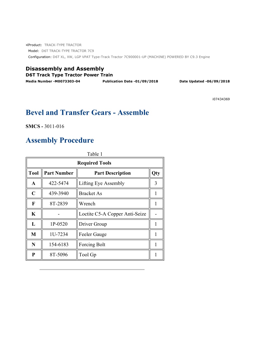
D6T XL, XW, LGP VPAT Type-Track Tractor 7C900001-UP (MACHINE) POWER... 1/17 Product: TRACK-TYPE TRACTOR Model: D6T TRACK-TYPE TRACTOR 7C9 Configuration: D6T XL, XW, LGP VPAT Type-Track Tractor 7C900001-UP (MACHINE) POWERED BY C9.3 Engine Disassembly and Assembly D6T Track Type Tractor Power Train Media Number -M0073303-04 Publication Date -01/09/2018 Date Updated -06/09/2018 i07434369 Bevel and Transfer Gears - Assemble SMCS - 3011-016 Assembly Procedure Table 1 Required Tools Tool Part Number Part Description Qty A 422-5474 Lifting Eye Assembly 3 C 439-3940 Bracket As 1 F 8T-2839 Wrench 1 K - Loctite C5-A Copper Anti-Seize - L 1P-0520 Driver Group 1 M 1U-7234 Feeler Gauge 1 N 154-6183 Forcing Bolt 1 P 8T-5096 Tool Gp 1 https://127.0.0.1/sisweb/sisweb/techdoc/techdoc_print_page.jsp?returnurl=/sis... 2021/4/11
D6T XL, XW, LGP VPAT Type-Track Tractor 7C900001-UP (MACHINE) POWER... 2/17 Illustration 1 g06132214 1. Raise the temperature of roller bearing race (48). Install roller bearing race (48) on bevel gear and shaft (37). Illustration 2 g06130916 2. Install retaining ring (47) on bevel gear and shaft (37). Illustration 3 g06130915 https://127.0.0.1/sisweb/sisweb/techdoc/techdoc_print_page.jsp?returnurl=/sis... 2021/4/11
D6T XL, XW, LGP VPAT Type-Track Tractor 7C900001-UP (MACHINE) POWER... 3/17 Illustration 4 g06136393 NOTICE Bearing cone (36), retaining ring (38), bearing cups (39), spacer (45), and bearing cone (46) have to be replaced as a set. Do not mix new parts with old parts. 3. Raise the temperature of bearing cone (46) and spacer (45). Install bearing (46) and spacer (45) on bevel gear and shaft (37). Illustration 5 g06132266 4. Install tube assemblies (42) in the transmission case. 5. Attach a suitable lifting device to bevel gear and shaft (37). The weight of bevel gear and shaft (37) is approximately 59 kg (130 lb). 6. Position bevel gear and shaft (37) in the transmission case. https://127.0.0.1/sisweb/sisweb/techdoc/techdoc_print_page.jsp?returnurl=/sis... 2021/4/11
https://www.ebooklibonline.com Hello dear friend! Thank you very much for reading. Enter the link into your browser. The full manual is available for immediate download. https://www.ebooklibonline.com
D6T XL, XW, LGP VPAT Type-Track Tractor 7C900001-UP (MACHINE) POWER... 4/17 Illustration 6 g06130847 7. Align the dowel hole in race and roller assembly (43) with the hole in bearing cage (41). 8. Install race and roller assembly (43) in bearing cage (41). 9. Install dowel (44) in bearing cage (41). Illustration 7 g06130837 10. Position bearing cage (41) on the transmission case. 11. Install bolts (40). Tighten bolts (40) to a torque of 120 20 N m (89 15 lb ft). Illustration 8 g06130815 https://127.0.0.1/sisweb/sisweb/techdoc/techdoc_print_page.jsp?returnurl=/sis... 2021/4/11
D6T XL, XW, LGP VPAT Type-Track Tractor 7C900001-UP (MACHINE) POWER... 5/17 12. Install retaining ring (38) (not shown) in the center of bearing cage (35). 13. Lower the temperature of two bearing cups (39). Install bearing cups (39) in bearing cage (35). Illustration 9 g06133273 Illustration 10 g06326102 14. Install bearing cage (35) without the shims. 15. Install bolts (33) that hold bearing cage (35) to the transmission case. Do not tighten bolts (33). 16. Raise the temperature of bearing cone (36). Install bearing cone (36) on the bevel gear and shaft. 17. Install washer (29) (not shown) and bearing lock washer (28). 18. Apply Tooling (K) to the threads and the face of bearing locknut (30). Install bearing locknut (30) on the bevel gear shaft. 19. Use Tooling (F) to tighten bearing locknut (30) to a torque of 900 100 N m (664 74 lb ft). 20. Increment bearing locknut (30) to the closest tab/groove location and then bend the locking tab on bearing lock washer (28). https://127.0.0.1/sisweb/sisweb/techdoc/techdoc_print_page.jsp?returnurl=/sis... 2021/4/11
D6T XL, XW, LGP VPAT Type-Track Tractor 7C900001-UP (MACHINE) POWER... 6/17 Illustration 11 g06130749 21. Install speed sensors (32) and bolts (31). Illustration 12 g06134656 22. Raise the temperature of bearing cone (25) to 135 C (275 F) and install bearing cone (25) on bevel pinion gear (24). Use a 0.03 mm (0.001 inch) feeler gauge to ensure that bearing cone (25) is seated against bevel pinion gear (24). Illustration 13 g06134609 23. Align the splines and install transfer gear (23) on bevel pinion gear (24). https://127.0.0.1/sisweb/sisweb/techdoc/techdoc_print_page.jsp?returnurl=/sis... 2021/4/11
D6T XL, XW, LGP VPAT Type-Track Tractor 7C900001-UP (MACHINE) POWER... 7/17 24. Raise the temperature of bearing cone (22) to a maximum of 135 C (275 F) and install bearing cone (22) on transfer gear (23). Use a 0.03 mm (0.001 inch) feeler gauge to ensure that bearing cone (22) is seated against transfer gear (23). Illustration 14 g06130695 25. Lower the temperature of bearing cup (26). Install bearing cup (26) into the transmission case. Illustration 15 g06130663 26. Attach Tooling (C) and a suitable lifting device to pinion gear assembly (21). The weight of pinion gear assembly (21) is approximately 33 kg (73 lb). 27. Lower pinion gear assembly (21) into position in the transmission case. 28. Remove Tooling (C) from pinion gear assembly (21). https://127.0.0.1/sisweb/sisweb/techdoc/techdoc_print_page.jsp?returnurl=/sis... 2021/4/11
D6T XL, XW, LGP VPAT Type-Track Tractor 7C900001-UP (MACHINE) POWER... 8/17 Illustration 16 g06133278 29. Lower the temperature of bearing cup (19) and install bearing cup (19) in transfer case (7). Illustration 17 g06133279 30. Lower the temperature of bearing cup (20) and install bearing cup (20) in bearing cage (18). Illustration 18 g06130305 31. If removed, raise the temperature of bearing cone (15) and bearing cone (16) to a maximum temperature of 135 C (275 F). Install bearing cone (15) and bearing cone (16) on transfer gear (13). Use a 0.03 mm (0.001 inch) feeler gauge to ensure that the bearing cones are seated against transfer gear (13). https://127.0.0.1/sisweb/sisweb/techdoc/techdoc_print_page.jsp?returnurl=/sis... 2021/4/11
D6T XL, XW, LGP VPAT Type-Track Tractor 7C900001-UP (MACHINE) POWER... 9/17 Illustration 19 g06130299 32. Ensure that retaining ring (14) is installed in the retaining ring groove of transfer gear (13). Illustration 20 g06133283 33. Position transfer gear (13) in transfer case (7). Illustration 21 g06130261 34. If removed, use Tooling (L) to install bearing (12) in bearing cage (8). 35. If removed, lower the temperature of bearing cup (11) and install bearing cup (11) in bearing cage (8). https://127.0.0.1/sisweb/sisweb/techdoc/techdoc_print_page.jsp?returnurl=/sis... 2021/4/11
D6T XL, XW, LGP VPAT Type-Track Tractor 7C900001-UP (MACHINE) POWE... 10/17 Illustration 22 g06322819 36. Position bearing cage (18) without the shims on transfer case (7). Install two bolts (17). Space the bolts 180 degrees apart. Do not tighten bolts (17). 37. Position bearing cage (8) without the shims on transfer case (7). Install bolts (9). Space the bolts 180 degrees apart. Do not tighten bolts (9). 38. Use Tooling (L) to install seal (10). Illustration 23 g06135123 Illustration 24 g06135103 https://127.0.0.1/sisweb/sisweb/techdoc/techdoc_print_page.jsp?returnurl=/sis... 2021/4/11
D6T XL, XW, LGP VPAT Type-Track Tractor 7C900001-UP (MACHINE) POWE... 11/17 39. Attach Tooling (A) and a suitable lifting device to transfer case (7). The weight of transfer case (7) is approximately 118 kg (260 lb). NOTICE Be sure that bolts (9) and (17) that hold bearing cages (8) and (18) in place on transfer case (7) are loose. 40. Position transfer case (7) on the transmission case. 41. Install new bolts (6) and washers. Tighten bolts (6) to a torque of 270 40 N m (199 30 lb ft). 42. Install roller bracket assembly (2) and bolts (3). Tighten bolts (3) to a torque of 270 40 N m (199 30 lb ft). Repeat for the roller bracket assembly on the opposite side. 43. Install retainer (5) and bolt (4). Tighten bolt (4) to a torque of 300 40 N m (221 30 lb ft). Illustration 25 g06326107 44. Install toric ring (1). Illustration 26 g06136027 https://127.0.0.1/sisweb/sisweb/techdoc/techdoc_print_page.jsp?returnurl=/sis... 2021/4/11
D6T XL, XW, LGP VPAT Type-Track Tractor 7C900001-UP (MACHINE) POWE... 12/17 45. Use the following Steps to adjust the bearing end play for the lower transfer gear: a. To seat the bearings, rotate the transfer gear at least three revolutions. Then, tighten bolts (9) evenly to a torque of 2.25 N m (20 lb in). b. Then, rotate the transfer gear at least three revolutions. Tighten bolts (9) evenly to a torque of 4.5 N m (40 lb in). c. Use Tooling (M) to measure the gap between bearing cage (8) and the transfer case. Measure the gap in four different places. Average the four measurements. d. Add 0.23 mm (0.009 inch) to the average figure that was obtained in Step 45.c. This figure will be the correct thickness for the shims that should be used. 46. Remove bearing cage (8). Put the correct thickness of shims in position on the transfer case. Put bearing cage (8) in position and install bolts (9) that hold bearing cage (8) in place. Tighten bolts (9) to a torque of 120 20 N m (89 15 lb ft). The bearing end play will be 0.10 0.05 mm (0.004 0.002 inch). Note: Checking bearing end play is not necessary if this procedure for adjustment has been followed. For a recordable measurement of the bearing end play, refer to Measurement of the Bearing End Play for the Bevel Pinion and Transfer Gears at the end of this procedure. Illustration 27 g06322822 47. Use the following Steps to adjust the bearing end play for the upper transfer and pinion gear: a. To seat the bearings, rotate the transfer and pinion gear at least three revolutions. Then, tighten bolts (17) evenly to a torque of 4.5 N m (40 lb in). b. Then, rotate the transfer and pinion gear at least three revolutions. Tighten bolts (17) evenly to a torque of 9.0 N m (80 lb in). c. Use Tooling (M) to measure the gap between bearing cage (18) and the transfer case. Measure the gap in four different places. Average the four measurements. d. Add 0.43 mm (0.017 inch) to the average figure that was obtained in Step 47.c. This figure will be the correct thickness for the shims that should be used. https://127.0.0.1/sisweb/sisweb/techdoc/techdoc_print_page.jsp?returnurl=/sis... 2021/4/11
D6T XL, XW, LGP VPAT Type-Track Tractor 7C900001-UP (MACHINE) POWE... 13/17 48. Remove bearing cage (18). Put the correct thickness of shims in position on the transfer case. Put bearing cage (18) in position and install bolts (17) that hold bearing cage (18) in place. Tighten bolts (17) to a torque of 120 20 N m (89 15 lb ft). The bearing end play will be 0.10 0.05 mm (0.004 0.002 inch). Note: Checking bearing end play is not necessary if this procedure for adjustment has been followed. For a recordable measurement of the bearing end play, refer to Measurement of the Bearing End Play for the Bevel Pinion and Transfer Gears at the end of this procedure. Illustration 28 g06322834 Illustration 29 g06136897 49. Position the transmission case as shown in Illustration 28 with the bevel gear and shaft in a vertical position and the bevel gear at the bottom. NOTICE The transmission case must be in this position. The bevel gear must be held as far away from the pinion gear as possible when the gear clearance (backlash) is set. https://127.0.0.1/sisweb/sisweb/techdoc/techdoc_print_page.jsp?returnurl=/sis... 2021/4/11
D6T XL, XW, LGP VPAT Type-Track Tractor 7C900001-UP (MACHINE) POWE... 14/17 50. Install Tooling (N) in the transfer case. Tighten Tooling (N) until there is no movement in the pinion gear. Be sure that Tooling (N) is between the teeth of the gear. 51. Put Tooling (P) in position and check the clearance (backlash) between the bevel gear and the pinion gear. The clearance (backlash) must be 0.30 + 0.12 mm 0.10 mm (0.012 + 0.005 inch 0.004 inch). Check the clearance (backlash) on three different teeth that are evenly spaced around the gear. 52. The difference between the high measurement and the low measurement must not be more than 0.15 mm (0.006 inch). 53. Install the correct amount of shims (34) under bearing cage (35). Install bolts (33) in bearing cage (35) and tighten bolts (33) to a torque of 120 20 N m (89 15 lb ft). 54. Check the gear clearance (backlash) to be certain that the clearance is still correct. If the clearance is not correct, add or remove shims (34), as needed. NOTICE Tooling (N) must be removed. 55. Remove Tooling (N) from the transfer case. End By: a. Connect the transmission and the bevel gears. Measurement of the Bearing End Play for the Bevel Pinion and Transfer Gears Table 2 Tooling Setup Item Part Number Part Description Qty R 5P-8247 Hard Washer 4 S 1P-1837 Bearing Puller Adapter 2 T 8T-4132 Nut 9 U 4B-5275 Washer 4 V 9U-7692 Threaded Rod (M16 x 2.0 x 610 mm) 1 W 2P-8260 Cylinder Liner Installer 1 X 8T-5096 Tool Gp 1 https://127.0.0.1/sisweb/sisweb/techdoc/techdoc_print_page.jsp?returnurl=/sis... 2021/4/11
D6T XL, XW, LGP VPAT Type-Track Tractor 7C900001-UP (MACHINE) POWE... 15/17 The bearing end play for the bevel pinion and transfer gears should be adjusted according to the procedure in Bevel and Transfer Gears - Assemble . If this procedure is used, the bearing end play (backlash) should be correctly set at 0.10 0.05 mm (0.004 0.002 inch). Illustration 30 g06138494 Illustration 31 g06139093 Measurement of the bearing end play for the transfer gear Illustration 32 g06139100 Measurement of the bearing end play for the pinion gear https://127.0.0.1/sisweb/sisweb/techdoc/techdoc_print_page.jsp?returnurl=/sis... 2021/4/11
D6T XL, XW, LGP VPAT Type-Track Tractor 7C900001-UP (MACHINE) POWE... 16/17 Note: Use the following Steps to measure the bearing clearance for the transfer gear. 1. The transfer gear is clamped to Tooling (S). Tooling (W) is used to force the transfer gear to turn. Tooling (R) fits in Tooling (S) to center Tooling (V) in the gear. 2. Install the Tooling in the transfer gear so that Tooling (V) and Tooling (S) are centered in the transfer gear. 3. Tighten Tooling (T) on top of the adapter to prevent movement of the transfer gear. Tooling (T) can then be used to turn the transfer gear. 4. Position the slotted end of Tooling (W) in a horizontal position on the threaded rod. Install Tooling (U) and Tooling (T) on Tooling (V). 5. Position Tooling (X). Be sure that the indicator tip is vertical and that the indicator tip is in contact with Tooling (S). 6. Rotate the transfer gear for at least three revolutions. Watch the needle on the dial indicator. Watch the backward movement and the forward movement. Stop rotating the transfer gear at the point of the maximum needle movement. Note: The needle may move back and forth during rotation due to runout in the adapter. Take the reading in the same location so that the measurement will be accurate and consistent. 7. Mark the location at the point of maximum needle movement on the surface of the adapter. Set the dial indicator to zero. 8. Force the transfer gear upward by pushing the lever downward. Record the reading. This reading will be the actual bearing clearance. The reading should be 0.10 0.05 mm (0.004 0.002 inch). 9. Repeat Steps 1 through 8. The result should be identical if Steps 1 through 8 were performed correctly. Note: Use the following Steps to measure the bearing clearance for the pinion gear. 10. Screw Tooling (V) in the pinion shaft. 11. Place Tooling (W) in position. 12. Adjust Tooling (W) so that the slotted end of the lever is horizontal. 13. Install Tooling (U) and Tooling (T) on Tooling (V). 14. Position Tooling (X) as shown. Be sure that the indicator tip is vertical and that the indicator tip is in contact with the flat end surface of the pinion gear. 15. Rotate the pinion gear for at least three revolutions. Watch the backward movement and the forward movement of the needle on the dial indicator as the pinion gear is being rotated. Stop rotating the pinion gear at the point of the maximum needle movement. Note: The needle may move back and forth during rotation due to runout in the surface of the pinion gear. Take the reading in the same location so that the measurement will be accurate and consistent. https://127.0.0.1/sisweb/sisweb/techdoc/techdoc_print_page.jsp?returnurl=/sis... 2021/4/11
D6T XL, XW, LGP VPAT Type-Track Tractor 7C900001-UP (MACHINE) POWE... 17/17 16. Mark the location at the point of maximum needle movement on the surface of the pinion gear. Set the dial indicator to zero. 17. Force the pinion gear upward by pushing the lever downward. Record the reading. This reading will be the actual bearing clearance. The reading should be 0.10 0.05 mm (0.004 0.002 inch). 18. Repeat Steps 10 through 17. The result should be identical if Steps 10 through 17 were performed correctly. https://127.0.0.1/sisweb/sisweb/techdoc/techdoc_print_page.jsp?returnurl=/sis... 2021/4/11
D6T XL, XW, LGP VPAT Type-Track Tractor 7C900001-UP (MACHINE) POWER... 1/30 Product: TRACK-TYPE TRACTOR Model: D6T TRACK-TYPE TRACTOR 7C9 Configuration: D6T XL, XW, LGP VPAT Type-Track Tractor 7C900001-UP (MACHINE) POWERED BY C9.3 Engine Disassembly and Assembly D6T Track Type Tractor Power Train Media Number -M0073303-04 Publication Date -01/09/2018 Date Updated -06/09/2018 i06746339 Transmission - Disassemble SMCS - 3030-015 Disassembly Procedure Table 1 Required Tools Tool Part Number Part Description Qty A 1P-2420 Transmission Repair Stand 1 B 136-1452 Retaining Ring Pliers As 1 C 421-5663 Lifting Eye Assembly 3 D 477-3190 Eyebolt Assembly 3 E 316-0706 Pliers - Locking 1 F 156-7100 Slide Hammer Puller Gp 1 G 421-5662 Lifting Eye Assembly 3 For access to a video of this procedure, scan the QR code below with a QR enabled device, or copy the link below. https://127.0.0.1/sisweb/sisweb/techdoc/techdoc_print_page.jsp?returnurl=/sis... 2021/4/11
D6T XL, XW, LGP VPAT Type-Track Tractor 7C900001-UP (MACHINE) POWER... 2/30 Table 2 Caterpillar Channel1 Media Number: CATU1334 Title: D6T Transmission Disassembly Channel1 URL: https://channel1.mediaspace.kaltura.com/media/D6T+Transmission+Repair/1_h6okgcnr Start By: a. Separate the transmission and bevel gears. Note: The transmission modulating valves must be recalibrated if any of the following procedures are performed: The transmission modulating valve and/or the solenoid is replaced. The transmission is serviced or the transmission is replaced. The electronic control module is replaced. Reference: Refer to Testing and Adjusting, "Transmission Clutch Pressure - Test". Note: The friction discs and the clutch plates from the individual clutches must be kept in the correct order. The friction discs and the clutch plates must be kept with the original clutch housings. The different clutches use different friction material. Do not mix the clutch plates and friction plates. https://127.0.0.1/sisweb/sisweb/techdoc/techdoc_print_page.jsp?returnurl=/sis... 2021/4/11
D6T XL, XW, LGP VPAT Type-Track Tractor 7C900001-UP (MACHINE) POWER... 3/30 Illustration 2 g06334890 Note: The weight of the transmission is approximately 458 kg (1010 lb). Mark the housings for alignment during the assembly procedure. 1. Remove O-ring seals (1) and (4) from the transmission cover. 2. Remove bolts (3) (not shown), and the strips (not shown). 3. Remove tubes (2) and the O-ring seals. 4. Remove fittings (5) and the O-ring seals. Remove locknut (6). Position the receptacle assembly into the case. Illustration 3 g06326832 5. Completely disconnect harness assembly (7) from all locations. 6. Remove bolts (8) and sensor (9). 7. Remove bolts (10) (not shown) and sensor (11). https://127.0.0.1/sisweb/sisweb/techdoc/techdoc_print_page.jsp?returnurl=/sis... 2021/4/11
D6T XL, XW, LGP VPAT Type-Track Tractor 7C900001-UP (MACHINE) POWER... 4/30 Illustration 4 g06101945 8. Remove O-ring seal (12) from sensor (9). Repeat for the other sensor. Illustration 5 g06334892 9. Remove bolts (13) and harness assembly (7). 10. Remove valve assemblies (14). Illustration 6 g06326123 11. Remove fitting (15), bolts (16), and solenoid valve (17) from valve assembly (14). https://127.0.0.1/sisweb/sisweb/techdoc/techdoc_print_page.jsp?returnurl=/sis... 2021/4/11
D6T XL, XW, LGP VPAT Type-Track Tractor 7C900001-UP (MACHINE) POWER... 5/30 Illustration 7 g06326138 12. Remove O-ring seals (18) from solenoid valve (17). 13. Repeat Steps 11 and 12 for the remaining valve assemblies (14). Illustration 8 g06326153 14. Remove valve assemblies (19) and the orifice plates. Illustration 9 g06326149 15. Remove fitting (20), nut (21), and coil assembly (22) from valve assembly (19). Repeat for the remaining valve assembly (19). https://127.0.0.1/sisweb/sisweb/techdoc/techdoc_print_page.jsp?returnurl=/sis... 2021/4/11
D6T XL, XW, LGP VPAT Type-Track Tractor 7C900001-UP (MACHINE) POWER... 6/30 Illustration 10 g06326224 16. Remove bolts (23) and valve assembly (24). Illustration 11 g06334897 Personal injury can result from parts and/or covers under spring pressure. Spring force will be released when covers are removed. Be prepared to hold spring loaded covers as the bolts are loosened. 17. Use a suitable prybar to raise hub clutch (28). Remove retaining ring (25). 18. Remove four bolts (29). 19. Remove bolts (26) and (30) in an alternating pattern until the spring force is relieved. 20. Remove manifold (27). https://127.0.0.1/sisweb/sisweb/techdoc/techdoc_print_page.jsp?returnurl=/sis... 2021/4/11
D6T XL, XW, LGP VPAT Type-Track Tractor 7C900001-UP (MACHINE) POWER... 7/30 Illustration 12 g06326230 21. Remove the retaining ring and bearing (31). Illustration 13 g06334986 22. Remove dowels (35), springs (33), and rods (34) (not shown). 23. Remove friction disc (32), clutch plate (36), and friction disc (37) (not shown). Illustration 14 g06334988 24. Remove seal rings (40) and O-ring seal (39). 25. Use Tooling (B) and two people to compress retaining ring (38). With retaining ring (38) compressed remove rotating housing (41) and retaining ring (38). https://127.0.0.1/sisweb/sisweb/techdoc/techdoc_print_page.jsp?returnurl=/sis... 2021/4/11
D6T XL, XW, LGP VPAT Type-Track Tractor 7C900001-UP (MACHINE) POWER... 8/30 Illustration 15 g06334989 Do not remove the retaining ring until the spring force has been released. Failure to do so could result in personal injury or death. In order to prevent this, use a suitable press to hold the spring force while the retaining ring is removed. Slowly release the spring tension with the press after the retaining ring has been removed. Note: Be sure not to overcompress bevel springs (44). Ensure that adequate space is between the tooling and retaining ring (41). 26. Position rotating housing (41) into a suitable press. 27. Use suitable tooling to apply pressure to ring (42). 28. Depress bevel springs (44) enough to remove retaining ring (43). 29. Remove ring (42). Illustration 16 g06326252 30. Remove springs (44) and note the orientation of springs (44) for assembly purposes. https://127.0.0.1/sisweb/sisweb/techdoc/techdoc_print_page.jsp?returnurl=/sis... 2021/4/11
D6T XL, XW, LGP VPAT Type-Track Tractor 7C900001-UP (MACHINE) POWER... 9/30 Illustration 17 g06326253 31. Remove piston (45) from rotating housing (41). Illustration 18 g06326254 32. Remove seal rings (46). Illustration 19 g06326256 33. Remove retaining ring (49). 34. Remove hub clutch (47), clutch discs (48), and the plates. https://127.0.0.1/sisweb/sisweb/techdoc/techdoc_print_page.jsp?returnurl=/sis... 2021/4/11
D6T XL, XW, LGP VPAT Type-Track Tractor 7C900001-UP (MACHINE) POWE... 10/30 Illustration 20 g06326259 35. Remove retaining ring (50) and hub clutch (51). Illustration 21 g06334991 Note: Rotate output shaft (54) as needed to gain access to all bolts (53). 36. Remove retaining rings (52) and bolts (53). Illustration 22 g06326263 https://127.0.0.1/sisweb/sisweb/techdoc/techdoc_print_page.jsp?returnurl=/sis... 2021/4/11
D6T XL, XW, LGP VPAT Type-Track Tractor 7C900001-UP (MACHINE) POWE... 11/30 Personal injury can result from parts and/or covers under spring pressure. Spring force will be released when covers are removed. Be prepared to hold spring loaded covers as the bolts are loosened. 37. Remove piston (59). 38. Remove nine bolts (55). 39. Equally loosen bolts (56) and (57) in an alternating pattern until the spring force is relieved. 40. Use two people to remove clutch housing (58). The weight of clutch housing (58) is approximately 35 kg (77 lb). Illustration 23 g06334994 41. Remove seal rings (60) from piston (59). Illustration 24 g06326267 42. Remove retaining ring (61) and hub assembly (62) from clutch housing (58). https://127.0.0.1/sisweb/sisweb/techdoc/techdoc_print_page.jsp?returnurl=/sis... 2021/4/11
Suggest: If the above button click is invalid. Please download this document first, and then click the above link to download the complete manual. Thank you so much for reading
D6T XL, XW, LGP VPAT Type-Track Tractor 7C900001-UP (MACHINE) POWE... 12/30 Illustration 25 g06326274 43. Remove seal rings (64) and bearing (63). Illustration 26 g06326486 44. Remove O-ring seal (65). Illustration 27 g06326493 45. Remove springs (66), rods (67) (not shown), and dowels (68). https://127.0.0.1/sisweb/sisweb/techdoc/techdoc_print_page.jsp?returnurl=/sis... 2021/4/11
https://www.ebooklibonline.com Hello dear friend! Thank you very much for reading. Enter the link into your browser. The full manual is available for immediate download. https://www.ebooklibonline.com

