Caterpillar Cat CS-533E, CP-533E Vibratory Compactor (Prefix BZG) Service Repair Manual Instant Download (BZG00001 and up)
Please open the website below to get the complete manualnn// n
Download Presentation

Please find below an Image/Link to download the presentation.
The content on the website is provided AS IS for your information and personal use only. It may not be sold, licensed, or shared on other websites without obtaining consent from the author. Download presentation by click this link. If you encounter any issues during the download, it is possible that the publisher has removed the file from their server.
E N D
Presentation Transcript
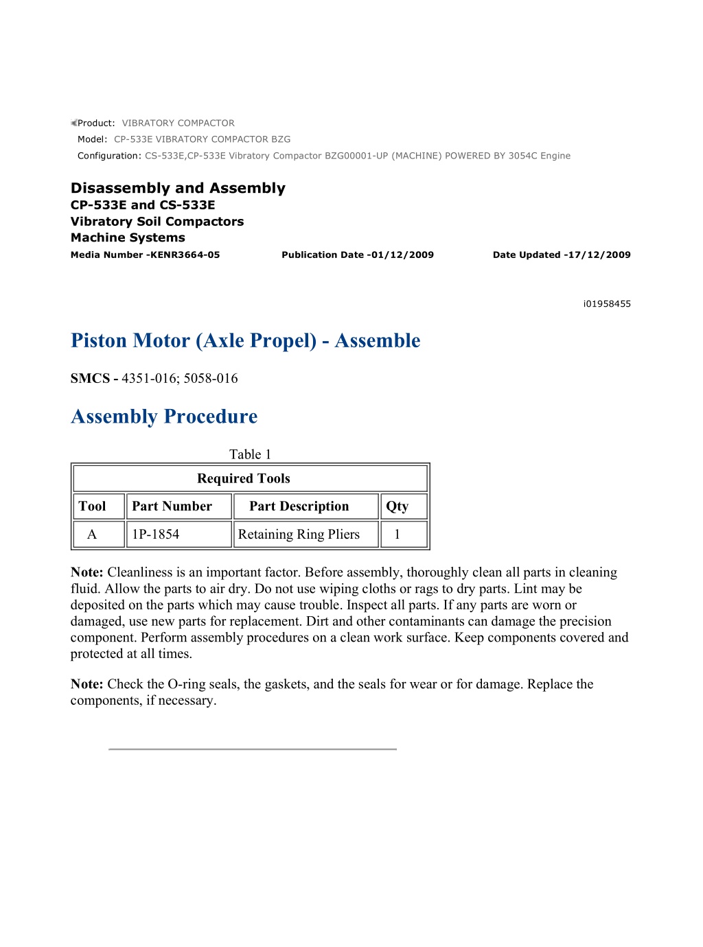
CS-533E,CP-533E Vibratory Compactor BZG00001-UP (MACHINE) POWERED B... 1/8 Product: VIBRATORY COMPACTOR Model: CP-533E VIBRATORY COMPACTOR BZG Configuration: CS-533E,CP-533E Vibratory Compactor BZG00001-UP (MACHINE) POWERED BY 3054C Engine Disassembly and Assembly CP-533E and CS-533E Vibratory Soil Compactors Machine Systems Media Number -KENR3664-05 Publication Date -01/12/2009 Date Updated -17/12/2009 i01958455 Piston Motor (Axle Propel) - Assemble SMCS - 4351-016; 5058-016 Assembly Procedure Table 1 Required Tools Tool Part Number Part Description Qty A 1P-1854 Retaining Ring Pliers 1 Note: Cleanliness is an important factor. Before assembly, thoroughly clean all parts in cleaning fluid. Allow the parts to air dry. Do not use wiping cloths or rags to dry parts. Lint may be deposited on the parts which may cause trouble. Inspect all parts. If any parts are worn or damaged, use new parts for replacement. Dirt and other contaminants can damage the precision component. Perform assembly procedures on a clean work surface. Keep components covered and protected at all times. Note: Check the O-ring seals, the gaskets, and the seals for wear or for damage. Replace the components, if necessary. https://127.0.0.1/sisweb/sisweb/techdoc/techdoc_print_page.jsp?returnurl=/sis... 2021/4/11
CS-533E,CP-533E Vibratory Compactor BZG00001-UP (MACHINE) POWERED B... 2/8 Illustration 1 g01018089 1. Use Tooling (A) in order to install retaining ring (25). Install seal (26) . Illustration 2 g01018088 2. Install bearing (23) and bearing cup (24) . Illustration 3 g01018087 3. Raise the temperature of bearing cone (22) . https://127.0.0.1/sisweb/sisweb/techdoc/techdoc_print_page.jsp?returnurl=/sis... 2021/4/11
CS-533E,CP-533E Vibratory Compactor BZG00001-UP (MACHINE) POWERED B... 3/8 4. Install bearing cone (22) . Illustration 4 g01018086 5. Install shaft (21) . Illustration 5 g01018085 6. Install swashplate (20) . https://127.0.0.1/sisweb/sisweb/techdoc/techdoc_print_page.jsp?returnurl=/sis... 2021/4/11
https://www.ebooklibonline.com Hello dear friend! Thank you very much for reading. Enter the link into your browser. The full manual is available for immediate download. https://www.ebooklibonline.com
CS-533E,CP-533E Vibratory Compactor BZG00001-UP (MACHINE) POWERED B... 4/8 Illustration 6 g01018084 7. Install plug (19) . Illustration 7 g01018083 8. Install plug (18) . Illustration 8 g01017903 https://127.0.0.1/sisweb/sisweb/techdoc/techdoc_print_page.jsp?returnurl=/sis... 2021/4/11
CS-533E,CP-533E Vibratory Compactor BZG00001-UP (MACHINE) POWERED B... 5/8 Illustration 9 g01017904 Improper assembly of parts that are spring loaded can cause bodily injury. To prevent possible injury, follow the established assembly procedure and wear protective equipment. 9. Use a suitable press and Tooling (A) in order to install retaining ring (14) . 10. Install spring (15), washer (16), and pins (17) into barrel assembly (10) . Illustration 10 g01017902 11. Install retaining ball (13) . 12. Install pistons (12) and plate (11) into barrel assembly (10) . https://127.0.0.1/sisweb/sisweb/techdoc/techdoc_print_page.jsp?returnurl=/sis... 2021/4/11
CS-533E,CP-533E Vibratory Compactor BZG00001-UP (MACHINE) POWERED B... 6/8 Illustration 11 g01017900 13. Install barrel assembly (10) . Illustration 12 g01017901 14. Install washer (9) . https://127.0.0.1/sisweb/sisweb/techdoc/techdoc_print_page.jsp?returnurl=/sis... 2021/4/11
CS-533E,CP-533E Vibratory Compactor BZG00001-UP (MACHINE) POWERED B... 7/8 Illustration 13 g01017899 15. Install bearing cone (8) . Illustration 14 g01017898 16. Install O-ring seal (7) from plug (5) . Illustration 15 g01017896 17. Install O-ring seal (6) . 18. Install plug (5) . https://127.0.0.1/sisweb/sisweb/techdoc/techdoc_print_page.jsp?returnurl=/sis... 2021/4/11
CS-533E,CP-533E Vibratory Compactor BZG00001-UP (MACHINE) POWERED B... 8/8 Illustration 16 g01017895 19. Install the bearing cup into cover (4) . 20. Install the bearing cup from cover (4) . Illustration 17 g01017893 21. Install bolts (1) and valve (2) . End By: Install the piston motor. Refer to Disassembly and Assembly, "Piston Motor (Axle Propel) - Install". https://127.0.0.1/sisweb/sisweb/techdoc/techdoc_print_page.jsp?returnurl=/sis... 2021/4/11
CS-533E,CP-533E Vibratory Compactor BZG00001-UP (MACHINE) POWERED B... 1/2 Product: VIBRATORY COMPACTOR Model: CP-533E VIBRATORY COMPACTOR BZG Configuration: CS-533E,CP-533E Vibratory Compactor BZG00001-UP (MACHINE) POWERED BY 3054C Engine Disassembly and Assembly CP-533E and CS-533E Vibratory Soil Compactors Machine Systems Media Number -KENR3664-05 Publication Date -01/12/2009 Date Updated -17/12/2009 i01943921 Piston Motor (Axle Propel) - Install SMCS - 4351-012; 5058-012 Installation Procedure Illustration 1 g01011553 1. Install the O-ring seal on axle propel motor (2). Position axle propel motor (2) on a suitable floor jack. Install the axle propel motor and bolts (3). The weight of the axle propel motor is approximately 36 kg (80 lb). 2. Install four hose assemblies (1) on axle propel motor (2) . 3. Fill housing (4) with oil. The capacity of the housing is approximately 0.5 L (0.13 US gal). 4. Fill the hydraulic oil tank with oil. The capacity of the hydraulic oil tank is approximately 80 L (21 US gal). Refer to Operation and Maintenance Manual, "Hydraulic System Oil - Change". https://127.0.0.1/sisweb/sisweb/techdoc/techdoc_print_page.jsp?returnurl=/sis... 2021/4/11
CS-533E,CP-533E Vibratory Compactor BZG00001-UP (MACHINE) POWERED B... 1/2 Product: VIBRATORY COMPACTOR Model: CP-533E VIBRATORY COMPACTOR BZG Configuration: CS-533E,CP-533E Vibratory Compactor BZG00001-UP (MACHINE) POWERED BY 3054C Engine Disassembly and Assembly CP-533E and CS-533E Vibratory Soil Compactors Machine Systems Media Number -KENR3664-05 Publication Date -01/12/2009 Date Updated -17/12/2009 i01861319 Final Drive Planetary (Axle Propel) - Remove SMCS - 4050-011 Removal Procedure Start By: a. Remove the axle propel motor. Refer to Disassembly and Assembly, "Piston Motor (Axle Propel) - Remove". Illustration 1 g00799772 1. Position a suitable lifting device under final drive planetary (1). 2. Remove bolts (2). Remove final drive planetary (1) and the O-ring seal from the axle. The weight of the final drive planetary is approximately 25 kg (55 lb). https://127.0.0.1/sisweb/sisweb/techdoc/techdoc_print_page.jsp?returnurl=/sis... 2021/4/11
CS-533E,CP-533E Vibratory Compactor BZG00001-UP (MACHINE) POWERED B... 1/4 Product: VIBRATORY COMPACTOR Model: CP-533E VIBRATORY COMPACTOR BZG Configuration: CS-533E,CP-533E Vibratory Compactor BZG00001-UP (MACHINE) POWERED BY 3054C Engine Disassembly and Assembly CP-533E and CS-533E Vibratory Soil Compactors Machine Systems Media Number -KENR3664-05 Publication Date -01/12/2009 Date Updated -17/12/2009 i01952143 Final Drive Planetary (Axle Propel) - Disassemble SMCS - 4050-015 Disassembly Procedure Start By: a. Remove the final drive planetary (axle propel). Refer to Disassembly and Assembly, "Final Drive Planetary (Axle Propel) - Remove". Illustration 1 g00984154 1. Remove bolts (2) and input flange (1). https://127.0.0.1/sisweb/sisweb/techdoc/techdoc_print_page.jsp?returnurl=/sis... 2021/4/11
CS-533E,CP-533E Vibratory Compactor BZG00001-UP (MACHINE) POWERED B... 2/4 Illustration 2 g00984155 2. Remove O-ring seal (3) from input flange (1). Illustration 3 g00984156 3. Remove sun gear (4). Illustration 4 g00984157 4. Remove planetary carrier (5). https://127.0.0.1/sisweb/sisweb/techdoc/techdoc_print_page.jsp?returnurl=/sis... 2021/4/11
CS-533E,CP-533E Vibratory Compactor BZG00001-UP (MACHINE) POWERED B... 3/4 Illustration 5 g00984210 5. Remove retaining ring (6) and washer (7) from planetary carrier (5). Illustration 6 g00984211 6. Remove planetary gear (8) from planetary carrier (5). Illustration 7 g00984212 7. Remove 38 needle bearings (9) and washer (11) from planetary carrier (5). 8. Remove cover (10) from planetary carrier (5). 9. Repeat Steps 5 through 7 and remove the remaining three planetary gears. https://127.0.0.1/sisweb/sisweb/techdoc/techdoc_print_page.jsp?returnurl=/sis... 2021/4/11
CS-533E,CP-533E Vibratory Compactor BZG00001-UP (MACHINE) POWERED B... 4/4 Illustration 8 g00984219 10. Remove ring gear (12) and the O-ring seal from output flange (14). 11. Remove spring pins (13) from ring gear (12). https://127.0.0.1/sisweb/sisweb/techdoc/techdoc_print_page.jsp?returnurl=/sis... 2021/4/11
CS-533E,CP-533E Vibratory Compactor BZG00001-UP (MACHINE) POWERED B... 1/4 Product: VIBRATORY COMPACTOR Model: CP-533E VIBRATORY COMPACTOR BZG Configuration: CS-533E,CP-533E Vibratory Compactor BZG00001-UP (MACHINE) POWERED BY 3054C Engine Disassembly and Assembly CP-533E and CS-533E Vibratory Soil Compactors Machine Systems Media Number -KENR3664-05 Publication Date -01/12/2009 Date Updated -17/12/2009 i02036591 Final Drive Planetary (Axle Propel) - Assemble SMCS - 4050-016 Assembly Procedure Table 1 Required Tools Tool Part Number Part Description Qty A 5P-0960 Molybdenum Grease 1 Illustration 1 g00984219 1. Install spring pins (13) in ring gear (12). 2. Install the O-ring seal and ring gear (12) on output flange (14). https://127.0.0.1/sisweb/sisweb/techdoc/techdoc_print_page.jsp?returnurl=/sis... 2021/4/11
CS-533E,CP-533E Vibratory Compactor BZG00001-UP (MACHINE) POWERED B... 2/4 Illustration 2 g00984212 3. Install cover (10) in planetary carrier (5). 4. Install washer (11) on the planetary gear pin. 5. Apply Tooling (A) on needle bearings (9). Install 38 needle bearings (9) on the planetary gear pin. There are two rows of needle bearings (9) on the planetary gear pin. Each row contains 19 needle bearings. Illustration 3 g00984211 6. Install planetary gear (8) on the needle bearings and planetary carrier (5). Illustration 4 g00984210 https://127.0.0.1/sisweb/sisweb/techdoc/techdoc_print_page.jsp?returnurl=/sis... 2021/4/11
CS-533E,CP-533E Vibratory Compactor BZG00001-UP (MACHINE) POWERED B... 3/4 7. Install washer (7) and retaining ring (6) on planetary carrier (5). 8. Repeat Steps 4 through 7 and install the remaining three planetary gears. Illustration 5 g00984157 9. Install planetary carrier (5). Illustration 6 g00984156 10. Install sun gear (4). Illustration 7 g00984155 https://127.0.0.1/sisweb/sisweb/techdoc/techdoc_print_page.jsp?returnurl=/sis... 2021/4/11
CS-533E,CP-533E Vibratory Compactor BZG00001-UP (MACHINE) POWERED B... 4/4 11. Install O-ring seal (3) in input flange (1). Illustration 8 g00984154 12. Position input flange (1) on the ring gear and install bolts (2). End By: a. Install the final drive planetary (axle propel). Refer to Disassembly and Assembly, "Final Drive Planetary (Axle Propel) - Install". https://127.0.0.1/sisweb/sisweb/techdoc/techdoc_print_page.jsp?returnurl=/sis... 2021/4/11
Suggest: For more complete manuals. Please go to the home page. https://www.ebooklibonline.com If the above button click is invalid. Please download this document first, and then click the above link to download the complete manual. Thank you so much for reading
CS-533E,CP-533E Vibratory Compactor BZG00001-UP (MACHINE) POWERED B... 1/2 Product: VIBRATORY COMPACTOR Model: CP-533E VIBRATORY COMPACTOR BZG Configuration: CS-533E,CP-533E Vibratory Compactor BZG00001-UP (MACHINE) POWERED BY 3054C Engine Disassembly and Assembly CP-533E and CS-533E Vibratory Soil Compactors Machine Systems Media Number -KENR3664-05 Publication Date -01/12/2009 Date Updated -17/12/2009 i02250928 Final Drive Planetary (Axle Propel) - Install SMCS - 4050-012 Installation Procedure Table 1 Required Tools Tool Part Number Part Description Qty A 9S-3263 Thread Lock Compound 1 Illustration 1 g00799772 1. Use a suitable lifting device to position the O-ring seal and final drive planetary (1) on the axle. The weight of the final drive planetary is approximately 25 kg (55 lb). Apply Tooling (A) on bolts (2) and install the bolts. https://127.0.0.1/sisweb/sisweb/techdoc/techdoc_print_page.jsp?returnurl=/sis... 2021/4/11
CS-533E,CP-533E Vibratory Compactor BZG00001-UP (MACHINE) POWERED B... 2/2 End By: Install the axle propel motor. Refer to Disassembly and Assembly, "Piston Motor (Axle Propel) - Install". https://127.0.0.1/sisweb/sisweb/techdoc/techdoc_print_page.jsp?returnurl=/sis... 2021/4/11
https://www.ebooklibonline.com Hello dear friend! Thank you very much for reading. Enter the link into your browser. The full manual is available for immediate download. https://www.ebooklibonline.com

