Caterpillar Cat CB66B Vibratory Compactor (Prefix 475) Service Repair Manual Instant Download (47500001 and up)
Please open the website below to get the complete manualnn//
Download Presentation

Please find below an Image/Link to download the presentation.
The content on the website is provided AS IS for your information and personal use only. It may not be sold, licensed, or shared on other websites without obtaining consent from the author. Download presentation by click this link. If you encounter any issues during the download, it is possible that the publisher has removed the file from their server.
E N D
Presentation Transcript
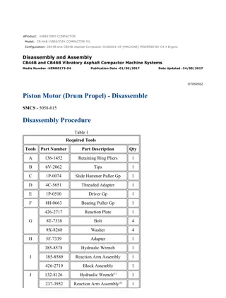
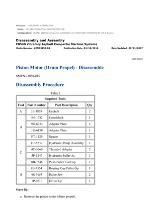
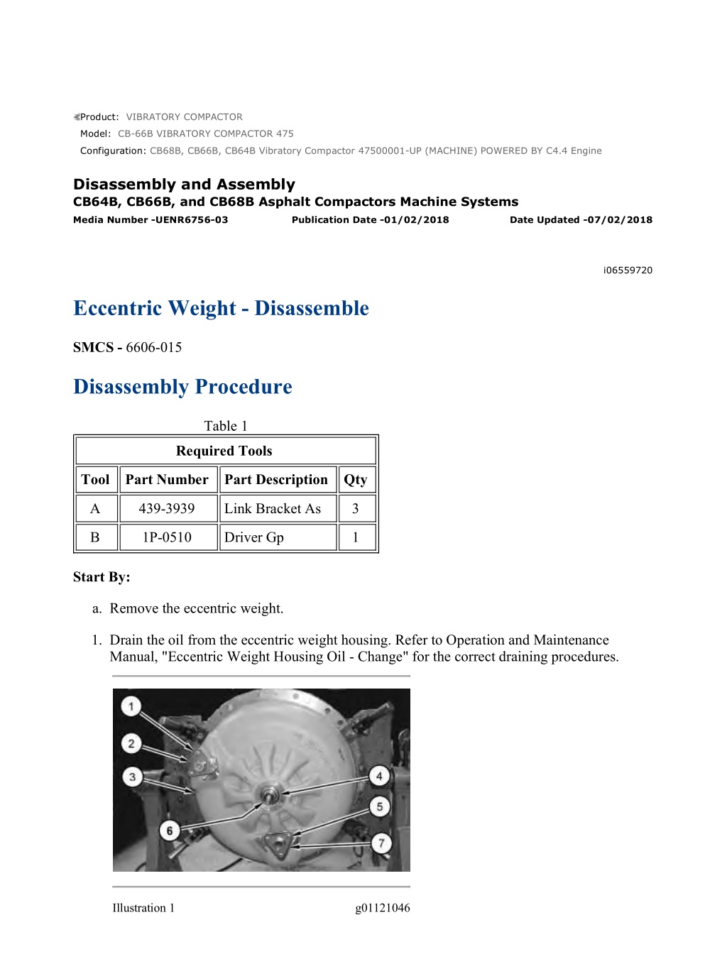
CB68B, CB66B, CB64B Vibratory Compactor 47500001-UP (MACHINE) POWERE... 1/7 Product: VIBRATORY COMPACTOR Model: CB-66B VIBRATORY COMPACTOR 475 Configuration: CB68B, CB66B, CB64B Vibratory Compactor 47500001-UP (MACHINE) POWERED BY C4.4 Engine Disassembly and Assembly CB64B, CB66B, and CB68B Asphalt Compactors Machine Systems Media Number -UENR6756-03 Publication Date -01/02/2018 Date Updated -07/02/2018 i06559720 Eccentric Weight - Disassemble SMCS - 6606-015 Disassembly Procedure Table 1 Required Tools Tool Part Number Part Description Qty A 439-3939 Link Bracket As 3 B 1P-0510 Driver Gp 1 Start By: a. Remove the eccentric weight. 1. Drain the oil from the eccentric weight housing. Refer to Operation and Maintenance Manual, "Eccentric Weight Housing Oil - Change" for the correct draining procedures. Illustration 1 g01121046 https://127.0.0.1/sisweb/sisweb/techdoc/techdoc_print_page.jsp?returnurl=/sisw... 2023/3/4
CB68B, CB66B, CB64B Vibratory Compactor 47500001-UP (MACHINE) POWERE... 2/7 2. Remove bolts (1), plate (2), bolts (5), and plate (7). 3. Remove dust cover (4) and lip seal (6) from eccentric weight assembly (3), if equipped. Illustration 2 g01218923 4. Remove cup plug (8), if equipped. Illustration 3 g01219057 5. Remove dust cover (9) and lip seal (10). Illustration 4 g01121048 https://127.0.0.1/sisweb/sisweb/techdoc/techdoc_print_page.jsp?returnurl=/sisw... 2023/3/4
CB68B, CB66B, CB64B Vibratory Compactor 47500001-UP (MACHINE) POWERE... 3/7 Note: Drive the pin out from the opposite side of the grooved end of the pins. 6. Remove pin (13) and bolts (12). 7. Attach Tooling (A) and a suitable lifting device to eccentric weight housing (11). The weight of eccentric weight housing (11) is approximately 58 kg (128 lb). Remove eccentric weight housing (11). Illustration 5 g01121050 8. Use a suitable lifting device to remove eccentric weight (14). The weight of eccentric weight (14) is approximately 50 kg (110 lb). Illustration 6 g06038176 9. Remove bolts (15) and bearing retainer (16). 10. Remove O-ring seal (17). https://127.0.0.1/sisweb/sisweb/techdoc/techdoc_print_page.jsp?returnurl=/sisw... 2023/3/4
https://www.ebooklibonline.com Hello dear friend! Thank you very much for reading. Enter the link into your browser. The full manual is available for immediate download. https://www.ebooklibonline.com
CB68B, CB66B, CB64B Vibratory Compactor 47500001-UP (MACHINE) POWERE... 4/7 Illustration 7 g06038183 11. Install plate (18A) onto bearing (18). Use plate (18A) and a suitable punch to remove bearing (18). Note: The dimensions of plate (18A) are: 50 mm wide, 100 mm long, and 12 mm thick. Illustration 8 g01121240 12. Remove bolts (20) and shaft (19). https://127.0.0.1/sisweb/sisweb/techdoc/techdoc_print_page.jsp?returnurl=/sisw... 2023/3/4
CB68B, CB66B, CB64B Vibratory Compactor 47500001-UP (MACHINE) POWERE... 5/7 Illustration 9 g01121241 13. Remove weight (21) from shaft (22). Illustration 10 g01121242 Personal injury can result from being struck by parts propelled by a released spring force. Make sure to wear all necessary protective equipment. Follow the recommended procedure and use all recommended tooling to release the spring force. 14. Remove bolts (23). Remove thrust block (24) from shaft (19). 15. Use Tooling (B) to remove bushing (25). Remove shaft (26). https://127.0.0.1/sisweb/sisweb/techdoc/techdoc_print_page.jsp?returnurl=/sisw... 2023/3/4
CB68B, CB66B, CB64B Vibratory Compactor 47500001-UP (MACHINE) POWERE... 6/7 Illustration 11 g01122175 Personal injury can result from being struck by parts propelled by a released spring force. Make sure to wear all necessary protective equipment. Follow the recommended procedure and use all recommended tooling to release the spring force. 16. Remove roll pin (28), spring (27), and key (29) from shaft (26). Illustration 12 g01121436 17. Remove weight assembly (30) from shaft (22). https://127.0.0.1/sisweb/sisweb/techdoc/techdoc_print_page.jsp?returnurl=/sisw... 2023/3/4
CB68B, CB66B, CB64B Vibratory Compactor 47500001-UP (MACHINE) POWERE... 7/7 Illustration 13 g01121437 Illustration 14 g01121045 18. Use Tooling (B) to remove bushing (31) from shaft (22). 19. Remove oil ring (32), sleeve bearing (33), and sleeves (34) from shafts (19) and (22). https://127.0.0.1/sisweb/sisweb/techdoc/techdoc_print_page.jsp?returnurl=/sisw... 2023/3/4
CB68B, CB66B, CB64B Vibratory Compactor 47500001-UP (MACHINE) POWERE... 1/10 Product: VIBRATORY COMPACTOR Model: CB-66B VIBRATORY COMPACTOR 475 Configuration: CB68B, CB66B, CB64B Vibratory Compactor 47500001-UP (MACHINE) POWERED BY C4.4 Engine Disassembly and Assembly CB64B, CB66B, and CB68B Asphalt Compactors Machine Systems Media Number -UENR6756-03 Publication Date -01/02/2018 Date Updated -07/02/2018 i07187769 Eccentric Weight - Disassemble - Versa Vib SMCS - 6606-015 Disassembly Procedure Tooling Table 1 Required Tools Tool Part Number Part Description Qty A 6V-2157 Link Bracket 3 B 8B-7554 Bearing Cup Puller Gp 1 C 1P-0510 Driver Gp 1 Disassembly Procedure 1. Drain the oil from the pod assembly. Refer to Operation and Maintenance Manual, Eccentric Weight Housing Oil - Change for the correct procedure. https://127.0.0.1/sisweb/sisweb/techdoc/techdoc_print_page.jsp?returnurl=/sisw... 2023/3/4
CB68B, CB66B, CB64B Vibratory Compactor 47500001-UP (MACHINE) POWERE... 2/10 Illustration 1 g06022515 2. Remove the three bolts, the three washers, fill plug assembly (1), and the seal from pod assembly (2). 3. Remove the three bolts, the three washers, sight glass assembly (3), and the seal from pod assembly (2). Illustration 2 g06023949 4. Remove dust cover (4) and lip seal (5). 5. Turn the pod assembly over. Illustration 3 g06023962 6. Remove dust cover (6) and lip seal (7). https://127.0.0.1/sisweb/sisweb/techdoc/techdoc_print_page.jsp?returnurl=/sisw... 2023/3/4
CB68B, CB66B, CB64B Vibratory Compactor 47500001-UP (MACHINE) POWERE... 3/10 Illustration 4 g06023549 7. Remove three bolts (8) and the three washers. Illustration 5 g06023566 8. Remove two pins (9). Note: Drive the pin out from the opposite side of the grooved end. Illustration 6 g06023968 https://127.0.0.1/sisweb/sisweb/techdoc/techdoc_print_page.jsp?returnurl=/sisw... 2023/3/4
CB68B, CB66B, CB64B Vibratory Compactor 47500001-UP (MACHINE) POWERE... 4/10 9. Attach Tooling (A) and a suitable lifting device to eccentric weight housing (10). The weight of eccentric weight housing (10) is approximately 58 kg (128 lb). Remove eccentric weight housing (10). Illustration 7 g06023990 10. Remove the bolts, the washers, and bearing retainer (11) from eccentric weight housing (10). Illustration 8 g06029268 (X) 100 mm (3.94 inch) (Y) 50 mm (1.97 inch) (Z) 12 mm (0.47 inch) 11. Dimensions of plate needed to remove bearing (12). https://127.0.0.1/sisweb/sisweb/techdoc/techdoc_print_page.jsp?returnurl=/sisw... 2023/3/4
CB68B, CB66B, CB64B Vibratory Compactor 47500001-UP (MACHINE) POWERE... 5/10 Illustration 9 g06029279 12. Use fabricated tool to remove bearing (12) from eccentric weight housing (10). Illustration 10 g06023994 13. Use a suitable lifting device to remove eccentric weight (13) from eccentric weight housing (14). The weight of eccentric weight (13) is approximately 50 kg (110 lb). Remove eccentric weight (13). Place eccentric weight (13) on a workbench. 14. Remove O-ring seal (15). Illustration 11 g06024390 https://127.0.0.1/sisweb/sisweb/techdoc/techdoc_print_page.jsp?returnurl=/sisw... 2023/3/4
CB68B, CB66B, CB64B Vibratory Compactor 47500001-UP (MACHINE) POWERE... 6/10 15. Remove the bolts, the washers, and bearing retainer (16) from eccentric weight housing (14). Illustration 12 g06029279 16. Turn housing (14) over and use fabricated tool to remove bearing (17). Illustration 13 g06024442 17. Remove seven bolts (18) and the seven washers. Illustration 14 g06024573 18. Use a suitable lifting device to remove shaft (19) from remove shaft (20). https://127.0.0.1/sisweb/sisweb/techdoc/techdoc_print_page.jsp?returnurl=/sisw... 2023/3/4
CB68B, CB66B, CB64B Vibratory Compactor 47500001-UP (MACHINE) POWERE... 7/10 Note: Shaft (19) is the shift end and shaft (20) is vibratory shaft end. Illustration 15 g06024593 19. Remove seal (21) from shaft (19). 20. Use Tool (B) to remove sleeve bearing (22) from shaft (19). Illustration 16 g06024602 21. Remove six bolts (23), the six washers, thrust block (24), and shaft assembly (25) from shaft (19). https://127.0.0.1/sisweb/sisweb/techdoc/techdoc_print_page.jsp?returnurl=/sisw... 2023/3/4
CB68B, CB66B, CB64B Vibratory Compactor 47500001-UP (MACHINE) POWERE... 8/10 Illustration 17 g06024604 22. Use Tool (C) and a suitable press to remove bushing (26) from thrust block (24). Illustration 18 g06024619 23. Remove spring (27). Illustration 19 g06024642 24. Place the shaft assembly into a vise. Remove spring pin (29). Remove shaft (30) from drive key (28). Illustration 20 g06025562 https://127.0.0.1/sisweb/sisweb/techdoc/techdoc_print_page.jsp?returnurl=/sisw... 2023/3/4
CB68B, CB66B, CB64B Vibratory Compactor 47500001-UP (MACHINE) POWERE... 9/10 25. Use Tool (C) to remove sleeve bearing (31) from shaft (19). Illustration 21 g06024664 26. Remove weight assembly (32) from shaft (20). Weight assembly (32) is approximately 16 kg (35 lb). Illustration 22 g06024649 27. Use Tool (C) and a suitable press to remove bushing (33). Illustration 23 g06025325 28. Use Tool (B) to remove sleeve bearing (34) from shaft (20). https://127.0.0.1/sisweb/sisweb/techdoc/techdoc_print_page.jsp?returnurl=/sisw... 2023/3/4
CB68B, CB66B, CB64B Vibratory Compactor 47500001-UP (MACHINE) POWERE... 1/9 Product: VIBRATORY COMPACTOR Model: CB-66B VIBRATORY COMPACTOR 475 Configuration: CB68B, CB66B, CB64B Vibratory Compactor 47500001-UP (MACHINE) POWERED BY C4.4 Engine Disassembly and Assembly CB64B, CB66B, and CB68B Asphalt Compactors Machine Systems Media Number -UENR6756-03 Publication Date -01/02/2018 Date Updated -07/02/2018 i06559809 Eccentric Weight - Assemble SMCS - 6606-016 Assembly Procedure Table 1 Required Tools Tool Part Number Part Description Qty A 439-3939 Link Bracket As 3 B 8B-7554 Bearing Cup Puller Gp 1 D 1P-0769 Seal Guide 1 E - Loctite 243 - F 281-9276 Seal Installer 1 G 281-9216 Driver 1 H 287-7476 Seal and Cover Driver 1 Loctite 263 Loctite 270(1) J - - K 287-7475 Plug Installer 1 L 281-9274 Seal and Cover Driver 1 M 287-7474 Seal and Cover Driver 1 (1)EAME Only https://127.0.0.1/sisweb/sisweb/techdoc/techdoc_print_page.jsp?returnurl=/sisw... 2023/3/4
CB68B, CB66B, CB64B Vibratory Compactor 47500001-UP (MACHINE) POWERE... 2/9 Illustration 1 g01121045 Illustration 2 g01121437 1. Use Tooling (D) and install sleeves (34) on shaft (19). Repeat for opposite shaft (22). 2. Use a suitable press and Tooling (B) to install sleeve bearing (33) in shaft (19). 3. Install oil ring (32) in shaft (19). 4. Use a suitable press and Tooling (B) to install bushing (31) in shaft (22). Illustration 3 g01121436 https://127.0.0.1/sisweb/sisweb/techdoc/techdoc_print_page.jsp?returnurl=/sisw... 2023/3/4
Suggest: For more complete manuals. Please go to the home page. https://www.ebooklibonline.com If the above button click is invalid. Please download this document first, and then click the above link to download the complete manual. Thank you so much for reading
CB68B, CB66B, CB64B Vibratory Compactor 47500001-UP (MACHINE) POWERE... 3/9 5. Install weight assembly (30) on shaft (22). Position the weight on weight assembly (30) opposite the timing mark on shaft (22). Illustration 4 g01122175 Illustration 5 g01123464 Improper assembly of parts that are spring loaded can cause bodily injury. To prevent possible injury, follow the established assembly procedure and wear protective equipment. 6. Position key (29) on shaft (26). Align the timing mark on key (29) with the keyway on shaft (26). 7. Install roll pin (28) and spring (27). 8. Install the shaft and key (29). Align the timing mark on key (29) with the timing mark on shaft (20). Align the timing mark on thrust block (25) with the timing mark on key (29). https://127.0.0.1/sisweb/sisweb/techdoc/techdoc_print_page.jsp?returnurl=/sisw... 2023/3/4
CB68B, CB66B, CB64B Vibratory Compactor 47500001-UP (MACHINE) POWERE... 4/9 Illustration 6 g01124087 Improper assembly of parts that are spring loaded can cause bodily injury. To prevent possible injury, follow the established assembly procedure and wear protective equipment. 9. Apply Tooling (E) to the threads of bolts (23). Install thrust block (24) and bolts (23) to shaft (19). 10. Use a suitable press and Tooling (B) to install bushing (25) in shaft (19). Illustration 7 g01121241 11. Align the timing mark on weight (21) with the timing mark on shaft (22). Install weight (21). https://127.0.0.1/sisweb/sisweb/techdoc/techdoc_print_page.jsp?returnurl=/sisw... 2023/3/4
https://www.ebooklibonline.com Hello dear friend! Thank you very much for reading. Enter the link into your browser. The full manual is available for immediate download. https://www.ebooklibonline.com

