Caterpillar Cat 962H WHEEL LOADER (Prefix J6J) Service Repair Manual Instant Download
Please open the website below to get the complete manualnn// n
Download Presentation

Please find below an Image/Link to download the presentation.
The content on the website is provided AS IS for your information and personal use only. It may not be sold, licensed, or shared on other websites without obtaining consent from the author. Download presentation by click this link. If you encounter any issues during the download, it is possible that the publisher has removed the file from their server.
E N D
Presentation Transcript
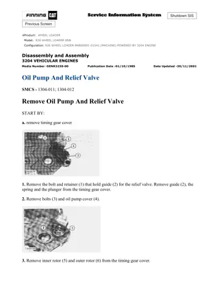
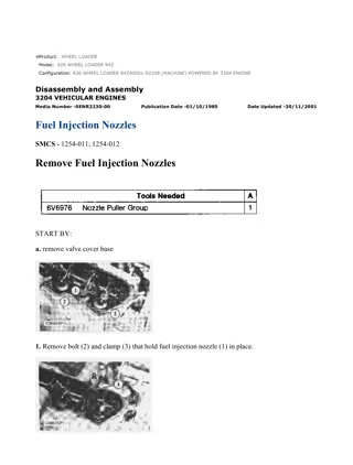
Service Repair Manual Models 962H WheelLoader
962H WHEEL LOADER J6J00001-UP (MACHINE) POWERED BY C7 ENGINE(X... 1/3 Shutdown SIS Previous Screen Product: WHEEL LOADER Model: 962H WHEEL LOADER J6J Configuration: 962H WHEEL LOADER J6J00001-UP (MACHINE) POWERED BY C7 ENGINE Disassembly and Assembly IT62H Integrated Toolcarrier and 950H and 962H Wheel Loaders Machine Systems Media Number -RENR8881-01 Publication Date -01/06/2009 Date Updated -08/06/2009 i02362326 Pilot Valve (Command Control Steering) - Install SMCS - 4342-012 Installation Procedure Note: Cleanliness is an important factor. Before assembly, all parts should be thoroughly cleaned in cleaning fluid. Allow the parts to air dry. Wiping cloths or rags should not be used to dry parts. Lint may be deposited on the parts which may cause later trouble. Inspect all parts. If any parts are worn or damaged, use new parts for replacement. Illustration 1 g00493364 1. Position steering pilot valve (6) and install bolts (5) . https://127.0.0.1/sisweb/sisweb/techdoc/techdoc_print_page.jsp?returnurl=/sis... 2020/3/22
962H WHEEL LOADER J6J00001-UP (MACHINE) POWERED BY C7 ENGINE(X... 2/3 Illustration 2 g00493363 2. Connect hose assemblies (4) . Illustration 3 g00439805 3. Place steering shaft (3) in the original position. Illustration 4 g00439803 4. Install bottom shaft yoke (1) on the shaft of the steering pilot valve. https://127.0.0.1/sisweb/sisweb/techdoc/techdoc_print_page.jsp?returnurl=/sis... 2020/3/22
https://www.ebooklibonline.com Hello dear friend! Thank you very much for reading. Enter the link into your browser. The full manual is available for immediate download. https://www.ebooklibonline.com
962H WHEEL LOADER J6J00001-UP (MACHINE) POWERED BY C7 ENGINE(X... 3/3 5. Install the nut and bolt (2) . End By: Separate the steering frame lock. Refer to Disassembly and Assembly, "Steering Frame Lock - Separate and Connect". Copyright 1993 - 2020 Caterpillar Inc. Sun Mar 22 13:14:47 UTC+0800 2020 All Rights Reserved. Private Network For SIS Licensees. https://127.0.0.1/sisweb/sisweb/techdoc/techdoc_print_page.jsp?returnurl=/sis... 2020/3/22
962H WHEEL LOADER J6J00001-UP (MACHINE) POWERED BY C7 ENGINE(X... 1/6 Shutdown SIS Previous Screen Product: WHEEL LOADER Model: 962H WHEEL LOADER J6J Configuration: 962H WHEEL LOADER J6J00001-UP (MACHINE) POWERED BY C7 ENGINE Disassembly and Assembly IT62H Integrated Toolcarrier and 950H and 962H Wheel Loaders Machine Systems Media Number -RENR8881-01 Publication Date -01/06/2009 Date Updated -08/06/2009 i02356712 Steering Control Valve (Command Control Steering) - Disassemble SMCS - 4307-015 Disassembly Procedure Start By: A. Remove the valve. Refer to Disassembly and Assembly, "Steering Control Valve (Command Control Steering) - Remove". Illustration 1 g01177250 Personal injury can result from being struck by parts propelled by a released spring force. https://127.0.0.1/sisweb/sisweb/techdoc/techdoc_print_page.jsp?returnurl=/sis... 2020/3/22
962H WHEEL LOADER J6J00001-UP (MACHINE) POWERED BY C7 ENGINE(X... 2/6 Make sure to wear all necessary protective equipment. Follow the recommended procedure and use all recommended tooling to release the spring force. 1. Remove bolts (1) and housing (2) . Illustration 2 g01177251 2. Remove O-ring seals (3) . Illustration 3 g01177252 Personal injury can result from being struck by parts propelled by a released spring force. Make sure to wear all necessary protective equipment. https://127.0.0.1/sisweb/sisweb/techdoc/techdoc_print_page.jsp?returnurl=/sis... 2020/3/22
962H WHEEL LOADER J6J00001-UP (MACHINE) POWERED BY C7 ENGINE(X... 3/6 Follow the recommended procedure and use all recommended tooling to release the spring force. 3. Remove bolts (4) and cover (5) . Illustration 4 g01177253 4. Remove O-ring seals (6) and spool assembly (7) . Illustration 5 g01177254 Personal injury can result from being struck by parts propelled by a released spring force. Make sure to wear all necessary protective equipment. https://127.0.0.1/sisweb/sisweb/techdoc/techdoc_print_page.jsp?returnurl=/sis... 2020/3/22
962H WHEEL LOADER J6J00001-UP (MACHINE) POWERED BY C7 ENGINE(X... 4/6 Follow the recommended procedure and use all recommended tooling to release the spring force. 5. Remove bolt (12), retainer (11), spring (10), and retainer (9) from spool (8) . Illustration 6 g01177255 6. Remove check valve (13), the O-ring seals, and the backup rings. Illustration 7 g01177256 7. Remove check valve (14), the O-ring seals, and the backup rings. https://127.0.0.1/sisweb/sisweb/techdoc/techdoc_print_page.jsp?returnurl=/sis... 2020/3/22
962H WHEEL LOADER J6J00001-UP (MACHINE) POWERED BY C7 ENGINE(X... 5/6 Illustration 8 g01177258 8. Remove check valve (15), the O-ring seals, and the backup rings. Illustration 9 g01177259 Personal injury can result from being struck by parts propelled by a released spring force. Make sure to wear all necessary protective equipment. Follow the recommended procedure and use all recommended tooling to release the spring force. 9. Remove plug (19), O-ring seal (20), spring (18), and ball (17) . 10. Repeat Step 2 for plug (16) . Sun Mar 22 13:15:45 UTC+0800 2020 https://127.0.0.1/sisweb/sisweb/techdoc/techdoc_print_page.jsp?returnurl=/sis... 2020/3/22
962H WHEEL LOADER J6J00001-UP (MACHINE) POWERED BY C7 ENGINE(X... 1/5 Shutdown SIS Previous Screen Product: WHEEL LOADER Model: 962H WHEEL LOADER J6J Configuration: 962H WHEEL LOADER J6J00001-UP (MACHINE) POWERED BY C7 ENGINE Disassembly and Assembly IT62H Integrated Toolcarrier and 950H and 962H Wheel Loaders Machine Systems Media Number -RENR8881-01 Publication Date -01/06/2009 Date Updated -08/06/2009 i02356713 Steering Control Valve (Command Control Steering) - Assemble SMCS - 4307-016 Assembly Procedure Illustration 1 g01177259 Improper assembly of parts that are spring loaded can cause bodily injury. To prevent possible injury, follow the established assembly procedure and wear protective equipment. https://127.0.0.1/sisweb/sisweb/techdoc/techdoc_print_page.jsp?returnurl=/sis... 2020/3/22
962H WHEEL LOADER J6J00001-UP (MACHINE) POWERED BY C7 ENGINE(X... 2/5 1. Install ball (17), spring (18), O-ring seal (20), and plug (19) . 2. Repeat Step 1 for plug (16) . Illustration 2 g01177258 3. Install the backup rings, the O-ring seals, and check valve (15) . Illustration 3 g01177256 4. Install the backup rings, the O-ring seals, and check valve (14) . https://127.0.0.1/sisweb/sisweb/techdoc/techdoc_print_page.jsp?returnurl=/sis... 2020/3/22
962H WHEEL LOADER J6J00001-UP (MACHINE) POWERED BY C7 ENGINE(X... 3/5 Illustration 4 g01177255 5. Install the backup rings, the O-ring seals, and check valve (13) . Illustration 5 g01177254 Improper assembly of parts that are spring loaded can cause bodily injury. To prevent possible injury, follow the established assembly procedure and wear protective equipment. 6. Install retainer (9), spring (10), retainer (11), and bolt (12), onto spool (8) . https://127.0.0.1/sisweb/sisweb/techdoc/techdoc_print_page.jsp?returnurl=/sis... 2020/3/22
962H WHEEL LOADER J6J00001-UP (MACHINE) POWERED BY C7 ENGINE(X... 4/5 Illustration 6 g01177253 7. Install O-ring seals (6) and spool assembly (7) . Illustration 7 g01177252 Improper assembly of parts that are spring loaded can cause bodily injury. To prevent possible injury, follow the established assembly procedure and wear protective equipment. 8. Install cover (5) and bolts (4) . https://127.0.0.1/sisweb/sisweb/techdoc/techdoc_print_page.jsp?returnurl=/sis... 2020/3/22
962H WHEEL LOADER J6J00001-UP (MACHINE) POWERED BY C7 ENGINE(X... 5/5 Illustration 8 g01177251 9. Install O-ring seals (3) . Illustration 9 g01177250 10. Remove bolts (1) and housing (2) . End By: Install the valve. Refer to Disassembly and Assembly, "Steering Control Valve (Command Control Steering) - Install". Copyright 1993 - 2020 Caterpillar Inc. Sun Mar 22 13:16:42 UTC+0800 2020 All Rights Reserved. Private Network For SIS Licensees. https://127.0.0.1/sisweb/sisweb/techdoc/techdoc_print_page.jsp?returnurl=/sis... 2020/3/22
962H WHEEL LOADER J6J00001-UP (MACHINE) POWERED BY C7 ENGINE(X... 1/2 Shutdown SIS Previous Screen Product: WHEEL LOADER Model: 962H WHEEL LOADER J6J Configuration: 962H WHEEL LOADER J6J00001-UP (MACHINE) POWERED BY C7 ENGINE Disassembly and Assembly IT62H Integrated Toolcarrier and 950H and 962H Wheel Loaders Machine Systems Media Number -RENR8881-01 Publication Date -01/06/2009 Date Updated -08/06/2009 i02310110 Steering Neutralizer Valve (HMU Steering) - Disassemble SMCS - 4330-015 Disassembly Procedure Start By: a. Remove the steering neutralizer valve. Refer to Disassembly and Assembly, "Steering Neutralizer Vavle (HMU Steering) - Remove". Note: Cleanliness is an important factor. Before the disassembly procedure, the exterior of the component should be thoroughly cleaned. This will help to prevent dirt from entering the internal mechanism. Illustration 1 g01157175 https://127.0.0.1/sisweb/sisweb/techdoc/techdoc_print_page.jsp?returnurl=/sis... 2020/3/22
962H WHEEL LOADER J6J00001-UP (MACHINE) POWERED BY C7 ENGINE(X... 2/2 Personal injury can result from being struck by parts propelled by a released spring force. Make sure to wear all necessary protective equipment. Follow the recommended procedure and use all recommended tooling to release the spring force. 1. Remove boot (1). 2. Remove plug (7), O-ring seal (6), and spring (5). 3. Remove spool (3) from valve body (4). 4. Remove lip seal (2). Copyright 1993 - 2020 Caterpillar Inc. Sun Mar 22 13:17:39 UTC+0800 2020 All Rights Reserved. Private Network For SIS Licensees. https://127.0.0.1/sisweb/sisweb/techdoc/techdoc_print_page.jsp?returnurl=/sis... 2020/3/22
962H WHEEL LOADER J6J00001-UP (MACHINE) POWERED BY C7 ENGINE(X... 1/2 Shutdown SIS Previous Screen Product: WHEEL LOADER Model: 962H WHEEL LOADER J6J Configuration: 962H WHEEL LOADER J6J00001-UP (MACHINE) POWERED BY C7 ENGINE Disassembly and Assembly IT62H Integrated Toolcarrier and 950H and 962H Wheel Loaders Machine Systems Media Number -RENR8881-01 Publication Date -01/06/2009 Date Updated -08/06/2009 i02310111 Steering Neutralizer Valve (HMU Steering) - Assemble SMCS - 4330-016 Assembly Procedure Table 1 Required Tools Tool Part Number Part Description Qty A 1P-0510 Driver Gp 1 Note: Cleanliness is an important factor. Before assembly, all parts should be thoroughly cleaned in cleaning fluid. Allow the parts to air dry. Wiping cloths or rags should not be used to dry parts. Lint may be deposited on the parts which may cause later trouble. Inspect all parts. If any parts are worn or damaged, use new parts for replacement. https://127.0.0.1/sisweb/sisweb/techdoc/techdoc_print_page.jsp?returnurl=/sis... 2020/3/22
962H WHEEL LOADER J6J00001-UP (MACHINE) POWERED BY C7 ENGINE(X... 2/2 Illustration 1 g01157175 Personal injury can result from being struck by parts propelled by a released spring force. Make sure to wear all necessary protective equipment. Follow the recommended procedure and use all recommended tooling to release the spring force. 1. Use Tooling (A) to install lip seal (2). 2. Install spool (3) into valve body (4). 3. Install spring (5), O-ring seal (6), and plug (7). 4. Install boot (1). End By: a. Install the steering neutralizer valve. Refer to Disassembly and Assembly, "Steering Neutralizer Valve (HMU Steering) - Install". Copyright 1993 - 2020 Caterpillar Inc. Sun Mar 22 13:18:36 UTC+0800 2020 All Rights Reserved. Private Network For SIS Licensees. https://127.0.0.1/sisweb/sisweb/techdoc/techdoc_print_page.jsp?returnurl=/sis... 2020/3/22
962H WHEEL LOADER J6J00001-UP (MACHINE) POWERED BY C7 ENGINE(X... 1/3 Shutdown SIS Previous Screen Product: WHEEL LOADER Model: 962H WHEEL LOADER J6J Configuration: 962H WHEEL LOADER J6J00001-UP (MACHINE) POWERED BY C7 ENGINE Disassembly and Assembly IT62H Integrated Toolcarrier and 950H and 962H Wheel Loaders Machine Systems Media Number -RENR8881-01 Publication Date -01/06/2009 Date Updated -08/06/2009 i02336013 Steering Neutralizer Valve (Command Control Steering) - Remove SMCS - 4330-011 Removal Procedure Table 1 Required Tools Tool Part Number Part Description Qty FT-1114 Vacuum Cap 1 5P-0306 Vacuum Transducer 1 A 6V-4142 Fitting 1 5K-5068 Fitting 1 Start By: A. Connect the steering frame lock. Refer to Disassembly and Assembly, "Steering Frame Lock - Separate and Connect". Note: Cleanliness is an important factor. Before the disassembly procedure, the exterior of the component should be thoroughly cleaned. This will help to prevent dirt from entering the internal mechanism. Note: Put identification marks on all lines, on all hoses, on all wires, and on all tubes for installation purposes. Plug all lines, hoses, and tubes. This helps to prevent fluid loss and this helps to keep contaminants from entering the system. https://127.0.0.1/sisweb/sisweb/techdoc/techdoc_print_page.jsp?returnurl=/sis... 2020/3/22
962H WHEEL LOADER J6J00001-UP (MACHINE) POWERED BY C7 ENGINE(X... 2/3 Illustration 1 g01165944 1. Install Tooling (A) onto the hydraulic tank. Attach an air supply hose onto Tooling (A). Apply 276 to 414 kPa (40 to 60 psi) of air. This procedure will pull vacuum on the hydraulic system. Illustration 2 g01165945 2. Remove cover assembly (1) . Illustration 3 g01165960 https://127.0.0.1/sisweb/sisweb/techdoc/techdoc_print_page.jsp?returnurl=/sis... 2020/3/22
962H WHEEL LOADER J6J00001-UP (MACHINE) POWERED BY C7 ENGINE(X... 3/3 3. Disconnect hose assemblies (2) . 4. Remove bolts (3) and steering neutralizer valve (4) . Copyright 1993 - 2020 Caterpillar Inc. Sun Mar 22 13:19:34 UTC+0800 2020 All Rights Reserved. Private Network For SIS Licensees. https://127.0.0.1/sisweb/sisweb/techdoc/techdoc_print_page.jsp?returnurl=/sis... 2020/3/22
962H WHEEL LOADER J6J00001-UP (MACHINE) POWERED BY C7 ENGINE(X... 1/3 Shutdown SIS Previous Screen Product: WHEEL LOADER Model: 962H WHEEL LOADER J6J Configuration: 962H WHEEL LOADER J6J00001-UP (MACHINE) POWERED BY C7 ENGINE Disassembly and Assembly IT62H Integrated Toolcarrier and 950H and 962H Wheel Loaders Machine Systems Media Number -RENR8881-01 Publication Date -01/06/2009 Date Updated -08/06/2009 i02310068 Steering Neutralizer Valve (Command Control Steering) - Disassemble SMCS - 4330-015 Disassembly Procedure Start By: a. Remove the steering neutralizer valve. Refer to Disassembly and Assembly, "Steering Neutralizer Valve (Command Control Steering) - Remove". Note: Cleanliness is an important factor. Before the disassembly procedure, the exterior of the component should be thoroughly cleaned. This will help to prevent dirt from entering the internal mechanism. https://127.0.0.1/sisweb/sisweb/techdoc/techdoc_print_page.jsp?returnurl=/sis... 2020/3/22
962H WHEEL LOADER J6J00001-UP (MACHINE) POWERED BY C7 ENGINE(X... 2/3 Illustration 1 g01157020 Personal injury can result from being struck by parts propelled by a released spring force. Make sure to wear all necessary protective equipment. Follow the recommended procedure and use all recommended tooling to release the spring force. 1. Remove plug assembly (1), O-ring seal (2), spring (3), and ball (4). 2. Remove boot (5) and lip seal (6). 3. Remove stem (7). 4. Remove plug (10), O-ring seal (9), and spring (8). Copyright 1993 - 2020 Caterpillar Inc. Sun Mar 22 13:20:31 UTC+0800 2020 All Rights Reserved. https://127.0.0.1/sisweb/sisweb/techdoc/techdoc_print_page.jsp?returnurl=/sis... 2020/3/22
962H WHEEL LOADER J6J00001-UP (MACHINE) POWERED BY C7 ENGINE(X... 1/3 Shutdown SIS Previous Screen Product: WHEEL LOADER Model: 962H WHEEL LOADER J6J Configuration: 962H WHEEL LOADER J6J00001-UP (MACHINE) POWERED BY C7 ENGINE Disassembly and Assembly IT62H Integrated Toolcarrier and 950H and 962H Wheel Loaders Machine Systems Media Number -RENR8881-01 Publication Date -01/06/2009 Date Updated -08/06/2009 i02310069 Steering Neutralizer Valve (Command Control Steering) - Assemble SMCS - 4330-016 Assembly Procedure Table 1 Required Tools Tool Part Number Part Description Qty A 1P-0510 Driver Gp 1 Note: Cleanliness is an important factor. Before assembly, all parts should be thoroughly cleaned in cleaning fluid. Allow the parts to air dry. Wiping cloths or rags should not be used to dry parts. Lint may be deposited on the parts which may cause later trouble. Inspect all parts. If any parts are worn or damaged, use new parts for replacement. https://127.0.0.1/sisweb/sisweb/techdoc/techdoc_print_page.jsp?returnurl=/sis... 2020/3/22
962H WHEEL LOADER J6J00001-UP (MACHINE) POWERED BY C7 ENGINE(X... 2/3 Illustration 1 g01157020 Personal injury can result from being struck by parts propelled by a released spring force. Make sure to wear all necessary protective equipment. Follow the recommended procedure and use all recommended tooling to release the spring force. 1. Install spring (8), O-ring seal (9), and plug (10). 2. Install stem (7). 3. Use Tooling (A) to install lip seal (6). 4. Install boot (5). 5. Install ball (4), spring (3), O-ring seal (2), and plug assembly (1). End By: https://127.0.0.1/sisweb/sisweb/techdoc/techdoc_print_page.jsp?returnurl=/sis... 2020/3/22
Suggest: If the above button click is invalid. Please download this document first, and then click the above link to download the complete manual. Thank you so much for reading
962H WHEEL LOADER J6J00001-UP (MACHINE) POWERED BY C7 ENGINE(X... 3/3 a. Install the steering neutralizer valve. Refer to Disassembly and assembly, "Steering Neutralizer Vavle (Command Control Steering) - Install". Copyright 1993 - 2020 Caterpillar Inc. Sun Mar 22 13:21:28 UTC+0800 2020 All Rights Reserved. Private Network For SIS Licensees. https://127.0.0.1/sisweb/sisweb/techdoc/techdoc_print_page.jsp?returnurl=/sis... 2020/3/22
https://www.ebooklibonline.com Hello dear friend! Thank you very much for reading. Enter the link into your browser. The full manual is available for immediate download. https://www.ebooklibonline.com

