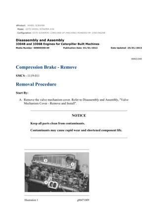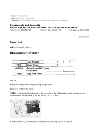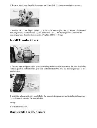
Caterpillar Cat 637G Wheel Scraper (Prefix CEJ) Service Repair Manual Instant Download
Please open the website below to get the complete manualnn// n
Download Presentation

Please find below an Image/Link to download the presentation.
The content on the website is provided AS IS for your information and personal use only. It may not be sold, licensed, or shared on other websites without obtaining consent from the author. Download presentation by click this link. If you encounter any issues during the download, it is possible that the publisher has removed the file from their server.
E N D
Presentation Transcript
w 1/11(W) Product: WHEEL SCRAPER Model: 637G WHEEL SCRAPER CEJ Configuration: 637G Wheel Scraper CEJ00001-UP (MACHINE) POWERED BY C-9 Engine Disassembly and Assembly 637G Wheel Tractor-Scraper Wheel Tractor Power Train Media Number -RENR5733-00 Publication Date -01/09/2004 Date Updated -30/09/2004 i02156910 Torque Converter - Assemble SMCS - 3101-016 Assembly Procedure Table 1 Required Tools Tool Part Number Part Description Qty A 138-7574 Link Bracket 3 B 1P-1861 Retaining Ring Pliers 1 C 1P-0510 Driver Gp 1 D 7X-0290 Bolt 2 NOTICE Keep all parts clean from contaminants. Contamination of the hydraulic system with foreign material will reduce the service life of the hydraulic system components. To prevent contaminants from entering the hydraulic system, always plug or cap the lines, fittings, or hoses as they are disconnected. Cover any disassembled components and clean them properly before assembly. Clean the hydraulic system properly after any major component exchange or especially after a component failure, to remove any contamination. https://127.0.0.1/sisweb/sisweb/techdoc/techdoc_print_page.jsp?returnurl=/sisweb/sisw... 2021/7/20
w 2/11(W) Illustration 1 g01094391 1. Lower the temperature of bearing (50). Install bearing (49) into housing (21) . Illustration 2 g01094044 2. Install the seals onto piston (49) and housing (21). Use Tooling (D) in order to install piston (49) into housing (21) . https://127.0.0.1/sisweb/sisweb/techdoc/techdoc_print_page.jsp?returnurl=/sisweb/sisw... 2021/7/20
w 3/11(W) Illustration 3 g01094037 3. Position housing (21), as shown. Install inner bearing race (48) . 4. Install disc assembly (47) . 5. Install plate (46). Install ring (45) . Illustration 4 g00835008 6. Install rings (43) onto shaft (44) . 7. Lower the temperature of bearing (42). Install bearing (42) onto shaft (44) . Illustration 5 g00833861 8. Install carrier (41). Install gear assembly (40) . https://127.0.0.1/sisweb/sisweb/techdoc/techdoc_print_page.jsp?returnurl=/sisweb/sisw... 2021/7/20
https://www.ebooklibonline.com Hello dear friend! Thank you very much for reading. Enter the link into your browser. The full manual is available for immediate download. https://www.ebooklibonline.com
w 4/11(W) Illustration 6 g00833858 9. Install impeller (39). Install carrier (38) . Illustration 7 g00833848 10. Install race (37). Install bearing (36) . Illustration 8 g00833847 11. Position stator (33), as shown. Install race (35). Install ring (34) . https://127.0.0.1/sisweb/sisweb/techdoc/techdoc_print_page.jsp?returnurl=/sisweb/sisw... 2021/7/20
w 5/11(W) Illustration 9 g00833825 12. Install stator (33). Install ring (32) . Illustration 10 g00833818 13. Install turbine (31). Install race (30). Install ring (29). Install bearing (28) . https://127.0.0.1/sisweb/sisweb/techdoc/techdoc_print_page.jsp?returnurl=/sisweb/sisw... 2021/7/20
w 6/11(W) Illustration 11 g00833808 14. Position hub (24), as shown. Install retainer (27) . Illustration 12 g00833799 15. Install carrier (26). Install ring (25) . Illustration 13 g00837760 16. Install hub (24). Install the shaft. Raise the temperature of bearing race (23). Install bearing race (23) on the shaft. 17. Install bolts (22). Tighten bolts (22) to a torque of 50 7 N m (37 5 lb ft). https://127.0.0.1/sisweb/sisweb/techdoc/techdoc_print_page.jsp?returnurl=/sisweb/sisw... 2021/7/20
w 7/11(W) Illustration 14 g00833716 18. Install Tooling (A). Position the torque converter, as shown. Install bolts (20). Tighten bolts (20) to a torque of 50 7 N m (37 5 lb ft). Install bolts (19). Tighten bolts (19) to a torque of 50 7 N m (37 5 lb ft). 19. Install torque converter assembly (18) into housing (21). The weight of torque converter assembly (18) is approximately 82 kg (180 lb). Illustration 15 g01095601 20. Install outer bearing race (17) . 21. Position retainer (16). Install bolts (15). Tighten bolts (15) to a torque of 50 7 N m (37 5 lb ft). https://127.0.0.1/sisweb/sisweb/techdoc/techdoc_print_page.jsp?returnurl=/sisweb/sisw... 2021/7/20
w 8/11(W) Illustration 16 g00833687 22. Position torque converter (14), as shown. Position flywheel pilot (13). Install bolts (12). Tighten bolts (12) to a torque of 50 7 N m (37 5 lb ft). Illustration 17 g00833678 23. Use Tooling (C) and a suitable press to install the bearing into gear (8) . Illustration 18 g00833676 https://127.0.0.1/sisweb/sisweb/techdoc/techdoc_print_page.jsp?returnurl=/sisweb/sisw... 2021/7/20
w 9/11(W) 24. Install shaft (11) . Illustration 19 g00833666 25. Use Tooling (B) in order to install retaining ring (10) to each side of gear (8) . Illustration 20 g00833655 26. Position housing assembly (7), as shown. 27. Install bolts (9). Position gear (8) . https://127.0.0.1/sisweb/sisweb/techdoc/techdoc_print_page.jsp?returnurl=/sisweb/sisw... 2021/7/20
w 10/11(W) Illustration 21 g00833647 28. Attach Tooling (A) and a suitable lifting device onto housing assembly (7) . 29. Position housing assembly (7). The weight of housing assembly (7) is approximately 118 kg (260 lb). Illustration 22 g00833629 30. Install retainer (6). Install bolts (5) . https://127.0.0.1/sisweb/sisweb/techdoc/techdoc_print_page.jsp?returnurl=/sisweb/sisw... 2021/7/20
w 11/11(W) Illustration 23 g00833624 31. Install carrier (3) . 32. Install ring (4) to carrier (3) on each side of retarder (2) . Illustration 24 g00833596 33. Install retarder (2). Install retaining ring (1) . End By: Connect the torque converter to the transmission. Refer to Disassembly and Assembly, "Torque Converter - Connect". https://127.0.0.1/sisweb/sisweb/techdoc/techdoc_print_page.jsp?returnurl=/sisweb/sisw... 2021/7/20
w 1/8(W) Product: WHEEL SCRAPER Model: 637G WHEEL SCRAPER CEJ Configuration: 637G Wheel Scraper CEJ00001-UP (MACHINE) POWERED BY C-9 Engine Disassembly and Assembly 637G Wheel Tractor-Scraper Wheel Tractor Power Train Media Number -RENR5733-00 Publication Date -01/09/2004 Date Updated -30/09/2004 i02156912 Transfer Gears - Disassemble SMCS - 3159-015 Disassembly Procedure Table 1 Required Tools Tool Part Number Part Description Qty A 1P-0520 Driver Gp 1 1P-0820 Hydraulic Puller 1 3H-0465 Push-Puller Plate 4 B 8B-7549 Puller Leg 2 8B-7551 Bearing Puller Gp 1 C 138-7573 Link Bracket 2 5F-7343 Bearing Puller Gp 1 D 1P-0520 Driver Gp 1 8B-7551 Bearing Puller Gp 1 E 1P-0520 Driver Gp 1 Start By: A. Remove the transmission. Refer to Disassembly and Assembly, "Torque Converter from Transmission - Separate". NOTICE https://127.0.0.1/sisweb/sisweb/techdoc/techdoc_print_page.jsp?returnurl=/sisweb/sisw... 2021/7/20
w 2/8(W) Care must be taken to ensure that fluids are contained during performance of inspection, maintenance, testing, adjusting and repair of the product. Be prepared to collect the fluid with suitable containers before opening any compartment or disassembling any component containing fluids. Refer to Special Publication, NENG2500, "Caterpillar Tools and Shop Products Guide" for tools and supplies suitable to collect and contain fluids on Caterpillar products. Dispose of all fluids according to local regulations and mandates. Illustration 1 g00834630 1. Remove cover (1) . Illustration 2 g00834574 2. Remove bolt (5). Remove retainer (6). Remove the O-ring seal. Remove yoke (4) . 3. Remove bolts (2). Remove cage assembly (3) . https://127.0.0.1/sisweb/sisweb/techdoc/techdoc_print_page.jsp?returnurl=/sisweb/sisw... 2021/7/20
w 3/8(W) Illustration 3 g00834584 4. Remove seal (7) from cage assembly (3) . Illustration 4 g00834586 5. Position cage assembly (3), as shown. Remove bolts (8). Remove plate (9). Remove O-ring seal (10) . https://127.0.0.1/sisweb/sisweb/techdoc/techdoc_print_page.jsp?returnurl=/sisweb/sisw... 2021/7/20
w 4/8(W) Illustration 5 g00834589 6. Use Tooling (A) and a suitable press in order to remove bearing (11) from cage assembly (3) . Illustration 6 g00834594 Note: If shaft (14) is not supported, the shaft will fall when bolt (13) is removed. 7. Position transfer case (12), as shown. Support shaft (14). Remove bolt (13). Remove the retainer. Remove shaft (14) . 8. Remove gear (15) from transfer case (12) . Illustration 7 g00834598 9. Use Tooling (B) in order to remove bearing (16) from shaft (14) . https://127.0.0.1/sisweb/sisweb/techdoc/techdoc_print_page.jsp?returnurl=/sisweb/sisw... 2021/7/20
w 5/8(W) Illustration 8 g00834608 10. Remove bolts (17) . Illustration 9 g00834615 11. Attach Tooling (C) and a suitable lifting device onto cage (18). Remove cage (18) and the pinion as a unit. The unit weighs approximately 34 kg (76 lb). Illustration 10 g00834620 https://127.0.0.1/sisweb/sisweb/techdoc/techdoc_print_page.jsp?returnurl=/sisweb/sisw... 2021/7/20
w 6/8(W) 12. Remove bolts (19). Remove plate (20). Remove bearing (21) . Illustration 11 g00834621 13. Use Tooling (D) and a suitable press in order to remove cage (18) from pinion (22) . Illustration 12 g00834623 14. If necessary, use Tooling (E) in order to remove bearing cone (23) from pinion (22). If necessary, use Tooling (E) in order to remove bearing cone (24) from pinion (22) . https://127.0.0.1/sisweb/sisweb/techdoc/techdoc_print_page.jsp?returnurl=/sisweb/sisw... 2021/7/20
w 7/8(W) Illustration 13 g01094451 15. Remove retaining ring (25) in order to remove bearing race (26) from cage (18) . Illustration 14 g00834626 16. Use Tooling (A) and a suitable press in order to remove the bearing race from cage (18) . Illustration 15 g00834628 17. Remove plug (27). Remove the dowel that holds the race in position. https://127.0.0.1/sisweb/sisweb/techdoc/techdoc_print_page.jsp?returnurl=/sisweb/sisw... 2021/7/20
w 8/8(W) Illustration 16 g00834629 18. Remove bearing race (28). Remove bearing race (29) . https://127.0.0.1/sisweb/sisweb/techdoc/techdoc_print_page.jsp?returnurl=/sisweb/sisw... 2021/7/20
w 1/9(W) Product: WHEEL SCRAPER Model: 637G WHEEL SCRAPER CEJ Configuration: 637G Wheel Scraper CEJ00001-UP (MACHINE) POWERED BY C-9 Engine Disassembly and Assembly 637G Wheel Tractor-Scraper Wheel Tractor Power Train Media Number -RENR5733-00 Publication Date -01/09/2004 Date Updated -30/09/2004 i05263976 Transfer Gears - Assemble SMCS - 3159-016 Assembly Procedure Table 1 Required Tools Tool Part Number Part Description Qty C 138-7573 Link Bracket 2 F 6V-2012 Depth Micrometer 1 G 8T-5096 Dial Indicator Gp 1 NOTICE Keep all parts clean from contaminants. Contamination of the hydraulic system with foreign material will reduce the service life of the hydraulic system components. To prevent contaminants from entering the hydraulic system, always plug or cap the lines, fittings, or hoses as they are disconnected. Cover any disassembled components and clean them properly before assembly. Clean the hydraulic system properly after any major component exchange or especially after a component failure, to remove any contamination. https://127.0.0.1/sisweb/sisweb/techdoc/techdoc_print_page.jsp?returnurl=/sisweb/sisw... 2021/7/20
w 2/9(W) Illustration 1 g00834629 1. Lower the temperature of bearing race (28) and race (29) . Install bearing race (28) and race (29) into case assembly. Align the hole in bearing race (29) to the case assembly. Illustration 2 g00834628 2. Install the dowel. Install plug (27) . https://127.0.0.1/sisweb/sisweb/techdoc/techdoc_print_page.jsp?returnurl=/sisweb/sisw... 2021/7/20
w 3/9(W) Illustration 3 g00834625 3. Raise the temperature of cage (18) . Lower the temperature of bearing race (26) . Install bearing race (26) into cage (18) . 4. Install retaining ring (25) into cage (18) . Illustration 4 g03350709 5. Raise the temperature of bearing (23) . Install bearing (23) onto pinion (22) . Install the bearing spacer. Illustration 5 g00834620 6. Raise the temperature of bearing (21) . Install bearing (21) . Install plate (20) . Install bolts (19) . https://127.0.0.1/sisweb/sisweb/techdoc/techdoc_print_page.jsp?returnurl=/sisweb/sisw... 2021/7/20
w 4/9(W) Illustration 6 g03350788 Illustration 7 g03350844 Illustration 8 g03350955 7. Use Tooling (F) to measure dimension Y and dimension Z record results. Use a micrometer to measure dimension X record results. Add measured results. X + Z = dimension B. Subtract dimension B from dimension Y. This is dimension W. Add shims (24a) to dimension W to achieve a measurement of 135.35 0.08 mm (5.328 0.003 inch). https://127.0.0.1/sisweb/sisweb/techdoc/techdoc_print_page.jsp?returnurl=/sisweb/sisw... 2021/7/20
w 5/9(W) Illustration 9 g03350962 8. Install bearing (24) . Illustration 10 g00834615 9. Attach Tooling (C) and a suitable lifting device. Position cage (18) and the pinion as a unit. The weight of the unit is approximately 34 kg (75 lb). Illustration 11 g00834608 https://127.0.0.1/sisweb/sisweb/techdoc/techdoc_print_page.jsp?returnurl=/sisweb/sisw... 2021/7/20
w 6/9(W) 10. Install bolts (17) . Illustration 12 g00834813 11. Raise the temperature of bearing (16) . Install bearing (16) onto shaft (14) . Illustration 13 g00834594 12. Position gear (15) in transfer case (12) . Install shaft (14) . Support shaft (14) . Install the retainer and install bolt (13) . Tighten bolt (13) to a torque of 115 7 N m (85 5 lb ft). https://127.0.0.1/sisweb/sisweb/techdoc/techdoc_print_page.jsp?returnurl=/sisweb/sisw... 2021/7/20
w 7/9(W) Illustration 14 g03351071 13. Install races and bearings (11) and (11a) into cage assembly (3) . Illustration 15 g00834586 14. Position cage assembly (3) , as shown. Install O-ring seal (10) . Position plate (9) . Install bolts (8) . Illustration 16 g00834584 https://127.0.0.1/sisweb/sisweb/techdoc/techdoc_print_page.jsp?returnurl=/sisweb/sisw... 2021/7/20
w 8/9(W) 15. Install seal (7) into cage assembly (3) . Illustration 17 g00834869 Illustration 18 g01094472 16. Install cage assembly (3) . Install Tooling (G) in order to check the backlash. Backlash must be maintained. Use the shims (not shown) in order to obtain a backlash of 0.15 to 0.33 mm (0.006 to 0.013 inch) between the gear and the pinion. Note: When you adjust the backlash, change the shim thickness by the same amount in both shim packs so that the top surfaces of gear (15) and pinion (22) remain equal. https://127.0.0.1/sisweb/sisweb/techdoc/techdoc_print_page.jsp?returnurl=/sisweb/sisw... 2021/7/20
Suggest: If the above button click is invalid. Please download this document first, and then click the above link to download the complete manual. Thank you so much for reading
w 9/9(W) Illustration 19 g00834879 17. Install yoke (4) . Install the O-ring seal. Install retainer (6) . Install bolt (5) . Tighten bolt (5) to a torque of 115 7 N m (85 5 lb ft). Illustration 20 g00834630 18. Install cover (1) . End By: Install the transmission. Refer to Disassembly and Assembly, "Torque Converter to Transmission - Connect". https://127.0.0.1/sisweb/sisweb/techdoc/techdoc_print_page.jsp?returnurl=/sisweb/sisw... 2021/7/20
https://www.ebooklibonline.com Hello dear friend! Thank you very much for reading. Enter the link into your browser. The full manual is available for immediate download. https://www.ebooklibonline.com

