Caterpillar Cat 637D WHEEL SCRAPER (Prefix 70W) Service Repair Manual Instant Download
Please open the website below to get the complete manualnn//
Download Presentation

Please find below an Image/Link to download the presentation.
The content on the website is provided AS IS for your information and personal use only. It may not be sold, licensed, or shared on other websites without obtaining consent from the author. Download presentation by click this link. If you encounter any issues during the download, it is possible that the publisher has removed the file from their server.
E N D
Presentation Transcript
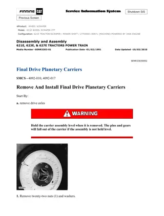
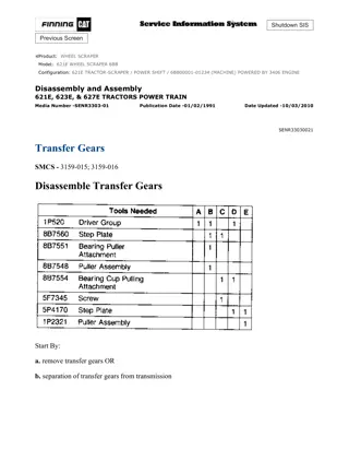
w 3/20(W) 1. Remove spiral snap ring (1), the adapter and drive shaft (2) for the transmission governor. 2. Install a 5/8"-11 NC forged eyebolt (3) in the top of transfer gear case (4). Fasten a hoist to the transfer gear case. Remove bolts (5) and install two 1/2"-13 NC forcing screws. Remove the transfer gear case from the transmission. Weight is 750 lb. (340 kg). Install Transfer Gears 1. Fasten a hoist and put transfer gear case (1) in position on the transmission. Be sure the O-ring seal is in position on the transfer gear case. Install the bolts that hold the transfer gear case to the transmission. 2. Install the adapter and drive shaft (2) for the transmission governor and install spiral snap ring (3) in the output shaft for the transmission. end by: a) install transmission Disassemble Transfer Gears https://127.0.0.1/sisweb/sisweb/techdoc/techdoc_print_page.jsp?returnurl=/sisweb/sis... 2021/10/18
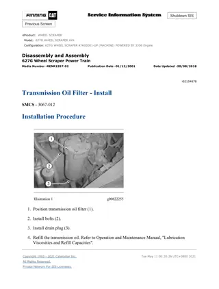
w 4/20(W) start by: a) remove transmission b) remove transfer gears 1. Remove transmission oil filter (1) from transfer gear housing after four bolts (3) are removed. Remove bolts (2) from cover assembly. 2. Remove cover assembly (4) and filter element (5) from filter housing. https://127.0.0.1/sisweb/sisweb/techdoc/techdoc_print_page.jsp?returnurl=/sisweb/sis... 2021/10/18
w 5/20(W) 3. Make a separation of the filter element (5) from cover assembly (4) after nut (7) is removed. Remove and inspect O-ring seal (6). Make a replacement if necessary. 4. Remove plug (10) from filter housing, then remove spring (9) and relief valve (8). 5. Remove two bolts and remove scavenge pump (11). Remove and inspect O-ring seal (12). Make a replacement if necessary. Remove coupling (13) from manifold housing. 6. Remove bolts (14) from scavenge pump cover. https://127.0.0.1/sisweb/sisweb/techdoc/techdoc_print_page.jsp?returnurl=/sisweb/sis... 2021/10/18
https://www.ebooklibonline.com Hello dear friend! Thank you very much for reading. Enter the link into your browser. The full manual is available for immediate download. https://www.ebooklibonline.com
w 6/20(W) 7. Make a separation of cover (15), body assembly (16) and cover (17). 8. Remove bearings (18) from the covers. 9. Remove four bolts to remove filter screen (22). Remove and inspect O-ring seal (21). Make a replacement if necessary. Remove four bolts (19) and cover (20). Remove and inspect O-ring seal from cover (20). Make a replacement of the O-ring seal if necessary. 10. Remove magnetic filter element (23) from housing. Remove bolts (24) from shift governor (25). Install two 3/8"-16 NC forcing screws into shift governor housing. 11. Remove shift governor and drive assembly from transfer gear housing. Remove drive gear (26) and the thrust washer from both sides of the drive gear. https://127.0.0.1/sisweb/sisweb/techdoc/techdoc_print_page.jsp?returnurl=/sisweb/sis... 2021/10/18
w 7/20(W) 12. Remove bolts from manifold assembly. Install 3/8"-16 NC forcing screws and make a separation of manifold assembly (28) from the dowels. Remove and inspect gasket (30). Remove two bolts (27) and transmission pump (29) from manifold assembly. Remove and inspect O-ring seals from bottom of transmission pump. 13. Remove bolts (31) from transmission pump cover. 14. Make a separation of cover (32), body assembly (36) and cover (33). Remove bearings (35) from covers. Remove and inspect O-ring seals (34) from covers (32) and (33). 15. Remove bolts from pump drive gear cage (37). Install two 3/8"-16 NC forcing screws and remove cage. Remove and inspect O-ring seal (38). Make a replacement if necessary. Remove shims (39). https://127.0.0.1/sisweb/sisweb/techdoc/techdoc_print_page.jsp?returnurl=/sisweb/sis... 2021/10/18
w 8/20(W) 16. Remove bearing race (40) from pump drive gear cage with tooling (B). 17. Remove pump drive gear assembly (41) from transfer gear housing. 18. Remove bearing cones (43) from gear (42) with tooling (D). 19. Remove bearing cup (44) from housing with a hammer and punch. https://127.0.0.1/sisweb/sisweb/techdoc/techdoc_print_page.jsp?returnurl=/sisweb/sis... 2021/10/18
w 9/20(W) 20. Remove bolts from drive gear cage (46). Install two 3/8"-16 NC forcing screws and remove cage. Remove and inspect O-ring seal (45). Make a replacement if necessary. Remove shims (47). 21. Remove bearing cup (48) from cage with tooling (C). 22. Turn transfer gear housing over. Remove bolts from transmission drive gear cage (49). Install two 3/8"-16 NC forcing screws and remove cage. Remove shims (50). 23. Remove bearing cup (52) from transmission drive gear cage with a hammer and punch. Remove transmission drive gear assembly (51) from transfer gear housing. https://127.0.0.1/sisweb/sisweb/techdoc/techdoc_print_page.jsp?returnurl=/sisweb/sis... 2021/10/18
w 10/20(W) 24. Remove six bolts (53) and remove gear (55) from gear (54). 25. Remove bearing cones (56) from gear (54) with tooling (A). 26. Remove bearing cup (57) from transfer gear housing with a hammer and punch. Remove drive gear assembly (58). 27. Remove bearing cones (59) from gear with tooling (D). https://127.0.0.1/sisweb/sisweb/techdoc/techdoc_print_page.jsp?returnurl=/sisweb/sis... 2021/10/18
w 11/20(W) 28. Turn transfer gear housing over. Remove three bolts (61) that hold idler gear (60). Remove idler gear. 29. Remove retaining ring from cage assembly on gear (62). Make a separation of bearing and cage assembly from gear (62) with a hammer and punch. NOTE: Punch goes through one of the holes (63). 30. Remove bearing (64) from cage assembly. Assemble Transfer Gears https://127.0.0.1/sisweb/sisweb/techdoc/techdoc_print_page.jsp?returnurl=/sisweb/sis... 2021/10/18
w 12/20(W) 1. Put bearing cage (1) on idler gear (2). Install bearing assembly with a hammer and punch. Install snap ring that holds bearing. 2. Install the idler gear (3) into the transfer gear housing with three bolts. 3. Heat bearing cones (4) to a maximum temperature of 300 F (149 C) and install them on the drive gear (5). https://127.0.0.1/sisweb/sisweb/techdoc/techdoc_print_page.jsp?returnurl=/sisweb/sis... 2021/10/18
w 13/20(W) 4. Install the drive gear assembly into the transfer gear housing. 5. Lower the temperature of the bearing race for the transmission drive gear. Put it in position, then use tooling (A) to make sure it correctly makes a seat. 6. Heat bearing cones (7) to a maximum temperature of 300 F (149 C) and install them on the transmission drive gear (8). Install gear (9) on transmission drive gear with six bolts (6). Tighten bolts to a torque of 36 2 lb.ft. (48.8 2.7 N m). 7. Install transmission drive gear assembly into transfer gear housing. https://127.0.0.1/sisweb/sisweb/techdoc/techdoc_print_page.jsp?returnurl=/sisweb/sis... 2021/10/18
w 14/20(W) 8. Lower the temperature of the bearing race for the transmission drive gear cage (10). Put it in position, then use tooling (B) to make sure it correctly makes a seat. 9. Install shims, transmission drive gear cage and bolts (11). 10. Install tooling (E) and measure end play in the gear. Add or remove shims under cage to get .006 .002 in. (0.15 0.05 mm) end play in gear. NOTE: Final torque for bolts (11) that hold cage to case is 36 2 lb.ft. (48.8 2.7 N m). 11. Turn transfer gear housing over. Lower the temperature of the bearing race for the pump drive gear. Put it in position, then use tooling (C) to make sure it correctly makes a seat. https://127.0.0.1/sisweb/sisweb/techdoc/techdoc_print_page.jsp?returnurl=/sisweb/sis... 2021/10/18
w 15/20(W) 12. Heat the bearing cones (12) for the pump drive gear (13) to a maximum temperature of 300 F (149 C). Install the bearing cones on the gear. Install the gear in transfer gear housing. 13. Lower temperature of the bearing cup for the pump drive gear cage (14). Put bearing cup in position, then use tooling (B) to make sure it makes a correct seat. Install new O-ring seal on cage (14) and install shims (15) and cage (14) on transfer gear housing. Install bolts that hold cage to housing. 14. Install tooling (E) and measure end play in gear. Add or remove shims under cage to get .006 .002 in. (0.15 0.05 mm) end play in gear. Tighten bolts (16) to a final torque of 36 2 lb.ft. (48.8 2.7 N m). 15. Lower the temperature of the bearing cup for the drive gear cage (17). Put cup in position, then use tooling (B) to make sure it makes a correct seat. https://127.0.0.1/sisweb/sisweb/techdoc/techdoc_print_page.jsp?returnurl=/sisweb/sis... 2021/10/18
w 16/20(W) 16. Install new O-ring seal (18) on cage (17). Install shims (19) and cage (17) on transfer gear housing. Install bolts that hold cage to housing. 17. Install tooling (E) and measure end play in gear. Add or remove shims under cage to get .006 .002 in. (0.15 0.05 mm) end play in gear. Tighten bolts (20) to a final torque of 36 2 lb.ft. (48.8 2.7 N m). 18. Install governor drive gear (21) with a thrust washer (22) on both sides of the gear. 19. Put governor housing (23) in position on the transfer gear housing and install the bolts that hold it. https://127.0.0.1/sisweb/sisweb/techdoc/techdoc_print_page.jsp?returnurl=/sisweb/sis... 2021/10/18
w 17/20(W) 20. Install bearings in transmission pump covers (24) with tooling (D). Install the bearings so the junctions in the bearings are 30 15 from the centerline of the bearing bores and toward the oil pump outlet passages. Install the bearings until they are .062 .010 in. (1.57 0.25 mm) in from the inside face of the covers. 21. Assemble cover (26), body assembly (25) and cover (27) for the transmission pump. 22. Install bolts (28) that hold cover. Install O-ring seals on bottom of pump. 23. Install transmission pump (29) on manifold assembly (30) with two bolts. Tighten the bolts to a torque of 36 2 lb.ft. (48.8 2.7 N m). https://127.0.0.1/sisweb/sisweb/techdoc/techdoc_print_page.jsp?returnurl=/sisweb/sis... 2021/10/18
w 18/20(W) 24. Install a new gasket (31) for manifold assembly on the transfer gear housing. Install manifold assembly and the bolts that hold it. 25. Install magnetic filter (32) into transfer gear housing. Install cover (34) and bolts (33). 26. Install a new O-ring seal (35) on cover of filter screen (36). Install filter screen in transfer gear housing with four bolts. 27. Install the bearings in the scavenge pump covers with the junctions in the bearings 30 15 from the center line of the bearing bores and toward the oil pump outlet passages. Install the bearings until they are .062 .010 in. (1.57 0.25 mm) in from the inside face of the covers. Assemble cover (37), body assembly (38) and cover (39). Install O-ring seals on bottom of pump. https://127.0.0.1/sisweb/sisweb/techdoc/techdoc_print_page.jsp?returnurl=/sisweb/sis... 2021/10/18
w 19/20(W) 28. Install coupling (41) in manifold assembly. Install scavenge pump (40) on manifold assembly. Tighten the bolts that hold the pump in place to a torque of 36 2 lb.ft. (48.8 2.7 N m). 29. Install relief valve (43), spring (42) and plug (44) into transmission oil filter housing. Tighten plug to a torque of 35 5 lb.ft. (47.5 6.8 N m). 30. Install a new O-ring seal (45) on filter cover (46). Install filter element (47) on cover with nut (48). Tighten the nut to a torque of 120 24 lb.in. (13.6 2.7 N m). Install filter element assembly in transmission oil filter housing. 31. Put transmission oil filter housing (49) on the transfer gear housing and install the four bolts (50) that hold it. end by: a) install transfer gears https://127.0.0.1/sisweb/sisweb/techdoc/techdoc_print_page.jsp?returnurl=/sisweb/sis... 2021/10/18
w 20/20(W) b) install transmission Copyright 1993 - 2021 Caterpillar Inc. Mon Oct 18 21:04:46 UTC+0800 2021 All Rights Reserved. Private Network For SIS Licensees. https://127.0.0.1/sisweb/sisweb/techdoc/techdoc_print_page.jsp?returnurl=/sisweb/sis... 2021/10/18
w 1/13(W) Shutdown SIS Previous Screen Product: WHEEL SCRAPER Model: 637D WHEEL SCRAPER 70W Configuration: 637D SCRAPER 70W00001-UP (MACHINE) Disassembly and Assembly 631D & 637D TRACTORS POWER TRAIN Media Number -SENR7261-01 Publication Date -01/05/1979 Date Updated -05/01/2016 SENR72610020 Torque Converter SMCS - 3100-11; 3100-12; 3100-15; 3100-16 https://127.0.0.1/sisweb/sisweb/techdoc/techdoc_print_page.jsp?returnurl=/sisweb/sis... 2021/10/18
w 2/13(W) Remove Torque Converter start by: a) remove transmission b) remove transmission hydraulic control valves c) remove transfer gears https://127.0.0.1/sisweb/sisweb/techdoc/techdoc_print_page.jsp?returnurl=/sisweb/sis... 2021/10/18
w 3/13(W) 1. Install the transmission on tool (A) as shown. 2. Remove several bolts (2) and fasten the transmission to tool (A). 3. Remove bolts (1) that hold the number five clutch housing to the transmission case. 4. Remove 12 bolts (3) that hold the number one clutch housing to the transmission case. Put a mark on the number one clutch housing and case for installation purpose. 5. Install two 1/2"-13 NC forged eyebolts in the transmission case. Fasten a hoist and remove the transmission case. Weight is 500 lb. (227 kg). 6. Remove spiral snap ring (4) and washer (5) from the shaft. 7. Remove two bolts (6) and install two 1/2"-13 NC forged eyebolts. https://127.0.0.1/sisweb/sisweb/techdoc/techdoc_print_page.jsp?returnurl=/sisweb/sis... 2021/10/18
w 4/13(W) 8. Fasten a hoist to the torque converter (7). Remove nuts (8) that hold the torque converter to the number one clutch housing. Remove the torque converter. Weight is 156 lb. (71 kg). Install Torque Converter 1. Fasten a hoist and install the torque converter on the number one clutch housing. 2. Install the nuts that hold the torque converter to the clutch housing. 3. Remove the two eyebolts and install the two bolts (3) in their place. Tighten the two bolts that were removed to a torque of 81 4 lb.ft. (109.8 5.4 N m). 4. Install washer (1) and spiral snap ring (2) on the shaft. https://127.0.0.1/sisweb/sisweb/techdoc/techdoc_print_page.jsp?returnurl=/sisweb/sis... 2021/10/18
w 5/13(W) 5. Fasten a hoist and install transmission case (4) in its original position. 6. Install the bolts that hold the number one and five clutch housings to the transmission case. 7. Remove the transmission from tool (A). end by: a) install transfer gears b) install transmission hydraulic control valves c) install transmission Disassemble Torque Converter start by: a) remove transmission b) remove torque converter 1. Remove spiral snap ring (1) and support (2) from the torque converter. NOTE: The bearing can not be removed from the support. https://127.0.0.1/sisweb/sisweb/techdoc/techdoc_print_page.jsp?returnurl=/sisweb/sis... 2021/10/18
w 6/13(W) 2. Remove the bolts that hold impeller (3) to the housing. Use two 3/8"-16 NC forcing screws to make a separation of the impeller and housing. 3. Remove the impeller from the housing. 4. Remove the bolts and plate that hold hub (4) to the impeller. Remove the hub from the impeller. 5. Remove carrier (5) and the stator as a unit from the turbine hub. 6. Remove seal (6) from the carrier. 7. Remove race (7) and bearing (8) from the carrier. 8. Remove ring (9) and plate (10) from stator (11). 9. Turn carrier and stator over. Hold the stator and turn carrier in a clockwise direction to release the one-way clutch. Pull the carrier out of the stator. The rollers and springs for the clutch will fall out of the stator as the carrier is removed. https://127.0.0.1/sisweb/sisweb/techdoc/techdoc_print_page.jsp?returnurl=/sisweb/sis... 2021/10/18
w 7/13(W) NOTE: Remove cam (14) only if a replacement of the cam or stator is to be made. 10. Remove ring (12) and plate (13) from stator (11). 11. Heat the stator and cam to a temperature of 300 F (149 C) for five minutes only. Remove cam (14) from the stator with a press while it is hot. 12. Remove bearing (16) from carrier (5). 13. Remove bearing (15) from carrier (5). 14. Remove hub (17) and the turbine as a unit. 15. Remove bearing (18) and the race under bearing (18) from the hub. https://127.0.0.1/sisweb/sisweb/techdoc/techdoc_print_page.jsp?returnurl=/sisweb/sis... 2021/10/18
Suggest: If the above button click is invalid. Please download this document first, and then click the above link to download the complete manual. Thank you so much for reading
w 8/13(W) 16. Remove race (20) from the hub. 17. Remove bolts (19) that hold turbine (21) and the ring to the hub. Remove the turbine from the hub. 18. Remove bearing (22) and the race under bearing (22) from the flange. 19. Turn housing (23) over and remove the bolts that hold flange (24) to the housing. 20. Install two 1/2"-13 NC forcing screws in the flange and remove the flange from the housing. 21. Remove bearing (25) from the flange. Assemble Torque Converter https://127.0.0.1/sisweb/sisweb/techdoc/techdoc_print_page.jsp?returnurl=/sisweb/sis... 2021/10/18
w 9/13(W) 1. Use tooling (A) to install the bearing in the flange until it is even with the top of the flange. 2. Install the flange on the housing as shown. Install the bolts that hold the flange to the housing and tighten them to a torque of 81 4 lb.ft. (109.8 5.4 N m). 3. Turn the housing over and install race (2) and bearing (1) on the flange as shown. https://127.0.0.1/sisweb/sisweb/techdoc/techdoc_print_page.jsp?returnurl=/sisweb/sis... 2021/10/18
https://www.ebooklibonline.com Hello dear friend! Thank you very much for reading. Enter the link into your browser. The full manual is available for immediate download. https://www.ebooklibonline.com

