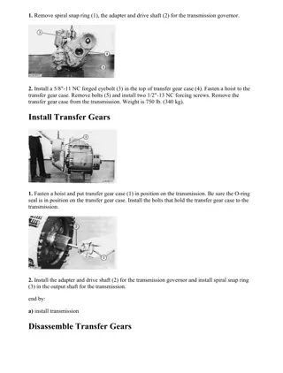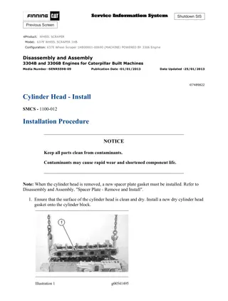
Caterpillar Cat 623F WHEEL SCRAPER (Prefix 3XW) Service Repair Manual Instant Download
Please open the website below to get the complete manualnn//
Download Presentation

Please find below an Image/Link to download the presentation.
The content on the website is provided AS IS for your information and personal use only. It may not be sold, licensed, or shared on other websites without obtaining consent from the author. Download presentation by click this link. If you encounter any issues during the download, it is possible that the publisher has removed the file from their server.
E N D
Presentation Transcript
w 1/9(W) Product: WHEEL SCRAPER Model: 623F WHEEL SCRAPER 3XW Configuration: 623F Wheel Tractor-Scraper 3XW00001-UP (MACHINE) POWERED BY 3406C Engine Disassembly and Assembly 623F Wheel Tractor-Scraper Machine Systems Media Number -RENR1466-00 Publication Date -01/11/1998 Date Updated -09/10/2001 i02323250 Vane Pump (Hydraulic and Steering) - Disassemble SMCS - 5055-015 Disassembly Procedure Table 1 Required Tools Tool Part Number Part Description Qty A 1P-1859 Retaining Ring Pliers 1 Start By: A. Remove the hydraulic and steering pump. Refer to Disassembly and Assembly, "Vane Pump (Hydraulic and Steering) - Remove". Illustration 1 g01035322 https://127.0.0.1/sisweb/sisweb/techdoc/techdoc_print_page.jsp?returnurl=/sisweb/sisw... 2021/4/25
w 2/9(W) 1. Remove bolts (2) that secure elbow (1) to the hydraulic and steering pump. Remove elbow (1) and the O-ring seal. Illustration 2 g01035323 2. Remove bolts (3) and cover (4) from cover assembly (5) . Illustration 3 g01035324 3. Remove O-ring seal (6) from cover (4) . https://127.0.0.1/sisweb/sisweb/techdoc/techdoc_print_page.jsp?returnurl=/sisweb/sisw... 2021/4/25
w 3/9(W) Illustration 4 g00508670 4. Remove cartridge assembly (7) from cover assembly (5) . Illustration 5 g00508671 5. Remove cover assembly (5) from body (8) . Illustration 6 g01035326 6. Remove cartridge assembly (9) and O-ring seal (10) from body (8) . https://127.0.0.1/sisweb/sisweb/techdoc/techdoc_print_page.jsp?returnurl=/sisweb/sisw... 2021/4/25
https://www.ebooklibonline.com Hello dear friend! Thank you very much for reading. Enter the link into your browser. The full manual is available for immediate download. https://www.ebooklibonline.com
w 4/9(W) Illustration 7 g01070055 7. Remove retaining ring (12) from body (8) . 8. Remove shaft (11) from body (8) . Illustration 8 g01070056 9. Remove washer (13) from body (8) . https://127.0.0.1/sisweb/sisweb/techdoc/techdoc_print_page.jsp?returnurl=/sisweb/sisw... 2021/4/25
w 5/9(W) Illustration 9 g01070057 10. Use Tooling (A) to remove retaining ring (15) from bearing (14) and shaft (11) . Illustration 10 g01070157 11. Use a suitable press to remove bearing (14) from shaft (11) . Illustration 11 g01035328 12. Remove lip seals (16) and O-ring seal (17) from body (8) . https://127.0.0.1/sisweb/sisweb/techdoc/techdoc_print_page.jsp?returnurl=/sisweb/sisw... 2021/4/25
w 6/9(W) Illustration 12 g00839071 13. Remove bolts (18) . Illustration 13 g00839074 14. Remove cap (19) . 15. Remove seals (20) and backup rings (21) . Illustration 14 g00839075 https://127.0.0.1/sisweb/sisweb/techdoc/techdoc_print_page.jsp?returnurl=/sisweb/sisw... 2021/4/25
w 7/9(W) 16. Remove plate (22) . Illustration 15 g00839059 Note: The arrow on cam ring (23) shows the direction of rotation of the vane pump. 17. Note the location of the arrow on cam ring (23) for assembly purposes. Illustration 16 g00839076 18. Remove cam ring (23) . https://127.0.0.1/sisweb/sisweb/techdoc/techdoc_print_page.jsp?returnurl=/sisweb/sisw... 2021/4/25
w 8/9(W) Illustration 17 g00839079 19. Remove vane assemblies (24). Note the direction of the sharp edges of the vanes in relation to pump rotation for assembly purposes. Illustration 18 g00839080 20. Remove rotor (25) and plate (26) . Illustration 19 g00839081 https://127.0.0.1/sisweb/sisweb/techdoc/techdoc_print_page.jsp?returnurl=/sisweb/sisw... 2021/4/25
w 9/9(W) 21. Remove seals (27) and backup ring (28) . 22. Repeat Steps 13 through 21 for the other cartridge assembly. https://127.0.0.1/sisweb/sisweb/techdoc/techdoc_print_page.jsp?returnurl=/sisweb/sisw... 2021/4/25
w 1/8(W) Product: WHEEL SCRAPER Model: 623F WHEEL SCRAPER 3XW Configuration: 623F Wheel Tractor-Scraper 3XW00001-UP (MACHINE) POWERED BY 3406C Engine Disassembly and Assembly 623F Wheel Tractor-Scraper Machine Systems Media Number -RENR1466-00 Publication Date -01/11/1998 Date Updated -09/10/2001 i02323252 Vane Pump (Hydraulic and Steering) - Assemble SMCS - 5055-016 Assembly Procedure Table 1 Required Tools Tool Part Number Part Description Qty A 1P-1859 Retaining Ring Pliers 1 B 1P-0510 Driver Group 1 C FT-0064 Spacer 1 NOTICE Keep all parts clean from contaminants. Contaminants may cause rapid wear and shortened component life. 1. Clean all parts and inspect all parts. If any parts are worn or damaged, use new parts for replacement. https://127.0.0.1/sisweb/sisweb/techdoc/techdoc_print_page.jsp?returnurl=/sisweb/sisw... 2021/4/25
w 2/8(W) Illustration 1 g00839081 2. Install backup ring (28) and seals (27) . Illustration 2 g00839080 3. Install plate (26) and rotor (25) . Illustration 3 g00839079 https://127.0.0.1/sisweb/sisweb/techdoc/techdoc_print_page.jsp?returnurl=/sisweb/sisw... 2021/4/25
w 3/8(W) 4. Install vane assemblies (24) with the sharp edge of the vanes in the direction of pump rotation. The arrow on the cam ring indicates the direction of pump rotation. Note: If the cam ring or the vanes are installed backward, the vane pump will not work. Illustration 4 g00839076 5. Install cam ring (23) . Illustration 5 g00839075 6. Install plate (22) with the bronze side toward the rotor. https://127.0.0.1/sisweb/sisweb/techdoc/techdoc_print_page.jsp?returnurl=/sisweb/sisw... 2021/4/25
w 4/8(W) Illustration 6 g00839074 7. Install seals (20) and backup rings (21) into cap (19) . 8. Install cap (19) . Illustration 7 g00839071 9. Install bolts (18). Tighten bolts (18) to a torque of 11 1 N m (97 9 lb in). 10. Repeat Steps 1 through 9 for the other cartridge assembly. https://127.0.0.1/sisweb/sisweb/techdoc/techdoc_print_page.jsp?returnurl=/sisweb/sisw... 2021/4/25
w 5/8(W) Illustration 8 g01035328 11. Install O-ring seal (17) to body (8). Use Tooling (B) to install lip seals (16) into body (8). Install the outer lip seal until the lip seal is seated in the body. Install the lip seal with the spring side toward the outside of the body. Install the inner lip seal until the lip seal is seated against the outer lip seal. Install the lip seal with the spring side of the lip seal toward the inside of the body. Lubricate both of the lip seals with the lubricant that is being sealed. Illustration 9 g01070056 12. Install washer (13) into body (8) . Illustration 10 g01070057 13. Raise the temperature of bearing (14). Install bearing (14) onto shaft (11). Use Tooling (A) to install retaining ring (15) . https://127.0.0.1/sisweb/sisweb/techdoc/techdoc_print_page.jsp?returnurl=/sisweb/sisw... 2021/4/25
w 6/8(W) Illustration 11 g01070055 14. Install shaft (11) into body (8). Install retaining ring (12) into body (8) . Illustration 12 g01035326 15. Install cartridge assembly (9) into body (8). Install O-ring seal (10) . Illustration 13 g00508671 16. Install cover assembly (5) onto body (8) . https://127.0.0.1/sisweb/sisweb/techdoc/techdoc_print_page.jsp?returnurl=/sisweb/sisw... 2021/4/25
w 7/8(W) Illustration 14 g00508670 17. Install cartridge assembly (7) into cover assembly (5) . Illustration 15 g01035324 18. Install O-ring seals (6) into cover (4) . https://127.0.0.1/sisweb/sisweb/techdoc/techdoc_print_page.jsp?returnurl=/sisweb/sisw... 2021/4/25
w 8/8(W) Illustration 16 g01035323 19. Install cover (4) onto cover assembly (5). Install bolts (3). Tighten bolts (3) to a torque of 359 14 N m (265 10 lb ft). Illustration 17 g01035322 20. Install the O-ring seal, elbow (2), and bolts (1) . End By: Install the hydraulic and steering pump. Refer to Disassembly and Assembly, "Vane Pump (Hydraulic and Steering) - Install". https://127.0.0.1/sisweb/sisweb/techdoc/techdoc_print_page.jsp?returnurl=/sisweb/sisw... 2021/4/25
w 1/4(W) Product: WHEEL SCRAPER Model: 623F WHEEL SCRAPER 3XW Configuration: 623F Wheel Tractor-Scraper 3XW00001-UP (MACHINE) POWERED BY 3406C Engine Disassembly and Assembly 623F Wheel Tractor-Scraper Machine Systems Media Number -RENR1466-00 Publication Date -01/11/1998 Date Updated -09/10/2001 i00995090 Vane Pump (Hydraulic and Steering) - Install SMCS - 5055-012 Installation Procedure NOTICE Keep all parts clean from contaminants. Contaminants may cause rapid wear and shortened component life. 1. Clean all parts and inspect all parts. If any parts are worn or damaged, use new Caterpillar parts for replacement. Illustration 1 g00518335 https://127.0.0.1/sisweb/sisweb/techdoc/techdoc_print_page.jsp?returnurl=/sisweb/sisw... 2021/4/25
w 2/4(W) 2. Install the O-ring seal and hydraulic and steering pump (6) to the machine. The hydraulic and steering pump weighs 55 kg (121 lb). Remove the tooling from the hydraulic and steering pump. Illustration 2 g00508020 3. Install the washers and two nuts (10) in order to secure hydraulic and steering pump (6) to the machine. Illustration 3 g00508017 4. Connect the O-ring seal and tube assembly (3) to hydraulic and steering pump (6) . Install the washers and four bolts (9) in order to secure tube assembly (3) to hydraulic and steering pump (6) . https://127.0.0.1/sisweb/sisweb/techdoc/techdoc_print_page.jsp?returnurl=/sisweb/sisw... 2021/4/25
Suggest: If the above button click is invalid. Please download this document first, and then click the above link to download the complete manual. Thank you so much for reading
w 3/4(W) Illustration 4 g00508015 5. Connect the O-ring seal and valve (8) to hydraulic and steering pump (6) . Install the washers and four bolts (7) in order to secure valve (8) to hydraulic and steering pump (6) . Illustration 5 g00508013 6. Connect the O-ring seal and valve (5) to hydraulic and steering pump (6) . Install the washers and four bolts (4) in order to secure valve (5) to hydraulic and steering pump (6) . Illustration 6 g00508012 https://127.0.0.1/sisweb/sisweb/techdoc/techdoc_print_page.jsp?returnurl=/sisweb/sisw... 2021/4/25
https://www.ebooklibonline.com Hello dear friend! Thank you very much for reading. Enter the link into your browser. The full manual is available for immediate download. https://www.ebooklibonline.com

