Caterpillar Cat 637E WHEEL SCRAPER (Prefix 7CB) Service Repair Manual Instant Download 7
Please open the website below to get the complete manualnn//
Download Presentation

Please find below an Image/Link to download the presentation.
The content on the website is provided AS IS for your information and personal use only. It may not be sold, licensed, or shared on other websites without obtaining consent from the author. Download presentation by click this link. If you encounter any issues during the download, it is possible that the publisher has removed the file from their server.
E N D
Presentation Transcript
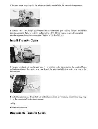
w 1/12(W) Product: WHEEL SCRAPER Model: 637E WHEEL SCRAPER 7CB Configuration: 637E Series II Wheel Tractor-Scraper (Coal) 7CB00180-UP (MACHINE) POWERED BY 3306 Engine Disassembly and Assembly 631E & 637E TRACTOR POWER TRAIN Media Number -SENR4143-01 Publication Date -01/10/2004 Date Updated -17/03/2010 SENR41430016 Transfer Gears SMCS - 3159-016; 3159-010; 3159-015 Remove And Install Transfer Gears 1. Turn the tractor 90 to the scraper. 2. Drain the oil from the transmission. 3. Fasten a hoist, and remove guard assembly (1) from the rear of the transmission. The weight of the guard assembly is 177 kg (390 lb.). 4. Remove the transmission electronic speed sensor. See the topic Remove Transmission Electronic Speed Sensor. 5. Remove the cushion hitch pump from the transfer gear case. See the topic Remove Cushion Hitch Pump in 631E, 637E Tractor-Scraper Vehicle Systems, Disassembly And Assembly module, Form No. SENR4153. https://127.0.0.1/sisweb/sisweb/techdoc/techdoc_print_page.jsp?returnurl=/sisweb/sisw... 2021/8/20
w 2/12(W) 6. Disconnect hose assembly (4) from the transmission oil filter. 7. Disconnect wire (3) from the lamp assembly. 8. Remove bolts (2) and (5), and move the wire harness away from the transfer gear case. 9. Remove transmission electronic speed sensor shaft (8). 10. Remove cover (9). Remove the O-ring seal from the cover. 11. Remove the retaining ring from the gear, behind cover (9). Pull the drive shaft out part way. Fasten a hoist to the drive shaft, and remove it from the transmission and transfer gears. The weight of the drive shaft is 38 kg (84 lb.). 12. Fasten tool (A) to implement and steering pump (7) to support it when the transfer gears are removed. 13. Remove the bolts that hold the implement and steering pump to the transfer gears. 14. Fasten a hoist and a 3/4"-10 NC forged eyebolt to transfer gears (6) as shown. 15. Remove the nuts and bolts that hold the transfer gears to the transmission. Install two 1/2"-13 NC forcing screws in the transfer gear case. Tighten the forcing screws evenly to separate the transfer gears for the transmission. Remove transfer gears (6). The weight of the transfer gears is 235 kg (518 lb.). NOTE: The following steps are for installation of the transfer gears. 16. Install two 1/2"-13 NC guide bolts in the transmission case. 17. Make sure the O-ring seals are in position on the transmission, transfer gear case and the implement and steering pump. Put clean oil on the O-ring seals. 18. Fasten a hoist and a 3/4"-10 NC forged eyebolt to transfer gears (6). https://127.0.0.1/sisweb/sisweb/techdoc/techdoc_print_page.jsp?returnurl=/sisweb/sisw... 2021/8/20
w 3/12(W) 19. Align the implement and steering pump with the gear in the transfer gears, and install the transfer gears on the transmission. 20. Install the nuts and bolts that hold the transfer gears in place. 21. Install the bolts that hold the implement and steering pump (7) to the transfer gear case. Remove tool (A). 22. Fasten a hoist to the drive shaft, and install the drive shaft in the transmission and transfer gears. 23. Install the retaining ring in the gear to hold the drive shaft in place. 24. Install the O-ring seal and cover (9). 25. Install transmission electronic speed sensor shaft (8). 26. Put the wire harness and clips in position, and install bolts (2) and (5). 27. Connect wire (3) to the lamp assembly. 28. Connect hose assembly (4) to the transmission oil filter base. 29. Install the transmission electronic speed sensor. 30. Install the cushion hitch pump. 31. Fasten a hoist to guard assembly (1), and install it on the rear of the transmission. 32. Fill the transmission with oil to the correct level. See the Maintanance Guide. Disassemble Transfer Gears START BY: a. remove transfer gears b. remove transmission oil filter c. remove transmission pump 1. Remove the bolts that hold cage assembly (2) to the case assembly. Install two 3/8"-16 NC forcing screws (1) in the cage assembly. Tighten the forcing screws evenly, and remove cage assembly (2). https://127.0.0.1/sisweb/sisweb/techdoc/techdoc_print_page.jsp?returnurl=/sisweb/sisw... 2021/8/20
https://www.ebooklibonline.com Hello dear friend! Thank you very much for reading. Enter the link into your browser. The full manual is available for immediate download. https://www.ebooklibonline.com
w 4/12(W) 2. Remove shims (3) from the case assembly. 3. Remove O-ring seal (5) from cage assembly (2). 4. If necessary, remove cup (4) from the cage assembly. 5. Remove gear (6) from the case assembly. 6. If necessary, remove cones (7) from the gear. 7. Remove the bolts that hold cage (8) to the case assembly. Install two 3/8"-16 NC forcing screws in cage (8). Tighten the forcing screws evenly, and remove the cage. 8. Remove shims (9) from the case assembly. https://127.0.0.1/sisweb/sisweb/techdoc/techdoc_print_page.jsp?returnurl=/sisweb/sisw... 2021/8/20
w 5/12(W) 9. Remove O-ring seal (11) from cage (8). 10. If necessary, remove cone (10) from the cage. 11. Remove gear (13) from the case assembly. 12. If necessary, remove cones (12) from the gear. 13. Remove the bolts that hold manifold (14) to the case assembly. Install two 3/8"-16 NC forcing screws in the manifold. Tighten the forcing screws evenly, and remove the manifold from the case assembly. 14. Turn the case assembly over. The weight of the case assembly is 200 kg (441 lb.). 15. Remove the bolts that hold cage (15) to the case assembly. Install two 3/8"-16 NC forcing screws in the cage. Tighten the forcing screws evenly, and remove the cage. 16. Remove shims (16) from the case assembly. https://127.0.0.1/sisweb/sisweb/techdoc/techdoc_print_page.jsp?returnurl=/sisweb/sisw... 2021/8/20
w 6/12(W) 17. Remove gear assembly (17) from the case assembly. 18. Disassemble gear assembly (17) as follows: a. Remove the bolts that hold gear (18) to gear (20). Install two 3/8"-16 NC forcing screws in gear (18). Tighten the forcing screws evenly, and remove the gear. b. If necessary, remove cones (19) from gear (20). 19. Align the holes in gear (21) with bolts (22). Remove bolts (22). 20. Align the holes in gear (21) with the forcing screw holes in the cage. 21. Install three 3/8"-16 NC forcing screws in the cage. Tighten the forcing screws evenly, and remove the cage and gear (21) as an assembly. https://127.0.0.1/sisweb/sisweb/techdoc/techdoc_print_page.jsp?returnurl=/sisweb/sisw... 2021/8/20
w 7/12(W) 22. Remove ring (24) from gear (21). 23. Install three 3/8"-16 NC forcing screws in cage (23). Tighten the forcing screws evenly, and remove the cage and bearing (25) from the gear. 24. Remove bearing (25) from cage (23). 25. If necessary, remove cups (26), (27) and (28) from the case assembly. 26. Remove tube assemblies (29) and (30) if necessary. Assemble Transfer Gears https://127.0.0.1/sisweb/sisweb/techdoc/techdoc_print_page.jsp?returnurl=/sisweb/sisw... 2021/8/20
w 8/12(W) 1. If tube assemblies (1) and (2) were removed, install the tube assemblies in the case assembly. 2. Make sure the ends of clips (3) are bent against the flat of the bolts after the bolts are installed. 3. If cups (4), (5) and (6) were removed from the case assembly, lower the temperature of the cups, and install them in the case assembly. 4. Use a press and tool (A), and install bearing (9) in cage (8). 5. Install the bearing and cage on gear (7) as shown, and install ring (10). 6. Put the cage and gear (7) in position in the case assembly, and install three bolts (11). Tighten bolts (11) to a torque of 50 7 N m (37 5 lb.ft.). https://127.0.0.1/sisweb/sisweb/techdoc/techdoc_print_page.jsp?returnurl=/sisweb/sisw... 2021/8/20
w 9/12(W) 7. If cones (13) were removed from gear (15), heat the cones to a maximum temperature of 135 C (275 F), and install cones (13) on the gear. 8. Put gear (12) in position on gear (15), and install bolts (14). Tighten bolts (14) to a torque of 50 7 N m (37 5 lb.ft.). 9. Put the gear assembly in position in the case assembly with gear (12) facing up as shown. 10. If cup (17) was removed from cage (16), lower the temperature of the cup, and install it in cage (16). 11. Put the original amount of shims (18) and cage (16) in position on the case assembly. Install the bolts that hold the cage in place. Tighten the bolts to a torque of 50 7 N m (37 5 lb.ft.). 12. Use tooling (B) to check the end play of gear (15). Add or subtract shims between cage (16) and the case assembly until the end play is 0.15 0.05 mm (.006 .002 in.). https://127.0.0.1/sisweb/sisweb/techdoc/techdoc_print_page.jsp?returnurl=/sisweb/sisw... 2021/8/20
w 10/12(W) 13. Turn the case assembly over. Put manifold (19) in position on the case assembly, and install bolts (20). 14. If cup (21) was removed from cage (22), lower the temperature of the cup, and install it in cage (22). 15. If cones (26) were removed from gear (24), heat the cones to a maximum temperature of 135 C (275 F), and install the cones on the gear. 16. Put gear (24) in position in the case assembly as shown. 17. Put the original amount of shims (25) and cage (22) without the O-ring seal in position on the case assembly. Install bolts (27). https://127.0.0.1/sisweb/sisweb/techdoc/techdoc_print_page.jsp?returnurl=/sisweb/sisw... 2021/8/20
w 11/12(W) 18. Use tool (B) to check the end play of gear (24). Add or subtract shims as needed until the end play is 0.15 0.05 mm (.006 .002 in.). 19. Remove bolts (27) and cage (22). 20. Install O-ring seal (23) on cage (22). 21. Put the correct amount of shims (25) and cage (22) in position on the case assembly, and install bolts (27). 22. If cup (29) was removed from cage assembly (28), lower the temperature of the cup, and install it in the cage assembly. 23. If cones (33) were removed from gear (32), heat the cones to a maximum temperature of 135 C (275 F), and install them on gear (32). 24. Install gear (32) in the case assembly. Install the gear with the wide shoulder of the gear toward the inside of the case assembly. 25. Put the original amount of shims (31) and cage assembly (29) without the O-ring seal in position on the case assembly. Install bolts (34). 26. Use tool (B) to check the end play of gear (32). Add or subtract shims between the cage assembly and the case assembly until the end play is 0.15 0.05 mm (.006 .002 in.). https://127.0.0.1/sisweb/sisweb/techdoc/techdoc_print_page.jsp?returnurl=/sisweb/sisw... 2021/8/20
w 12/12(W) 27. Remove bolts (34) and cage assembly (29). 28. Install O-ring seal (30) on cage assembly (29). 29. Put the correct amount of shims (31) and cage assembly (29) in position on the case assembly, and install bolts (34). END BY: a. install transmission pump b. install transmission oil filter c. install transfer gears https://127.0.0.1/sisweb/sisweb/techdoc/techdoc_print_page.jsp?returnurl=/sisweb/sisw... 2021/8/20
w 1/6(W) Product: WHEEL SCRAPER Model: 637E WHEEL SCRAPER 7CB Configuration: 637E Series II Wheel Tractor-Scraper (Coal) 7CB00180-UP (MACHINE) POWERED BY 3306 Engine Disassembly and Assembly 631E & 637E TRACTOR POWER TRAIN Media Number -SENR4143-01 Publication Date -01/10/2004 Date Updated -17/03/2010 SENR41430017 Transmission And Transfer Gears SMCS - 3176-011; 3176-012 Remove Transmission And Transfer Gears 1. Turn the tractor 90 to the scraper. 2. Drain the oil from the transmission and the differential housing. See the Maintenance Guide for the capacity. 3. Fasten a hoist, and remove guard assembly (1) from the rear of the transmission. The weight of the guard assembly is 177 kg (390 lb.). 4. Remove the nuts that hold the cushion hitch pump in place, and move it away from the transfer gear case. https://127.0.0.1/sisweb/sisweb/techdoc/techdoc_print_page.jsp?returnurl=/sisweb/sisw... 2021/8/20
w 2/6(W) 5. Disconnect wire (4) from the lamp assembly. 6. Disconnect wire harness (5) from the transmission electronic speed sensor. 7. Disconnect wire harness (3). 8. Remove the bolts that hold bracket (2) in place, and move the bracket and hoses away from the transmission. 9. Remove the bolts and clips that hold the wire harnesses in place. 10. Disconnect hose assembly (7) from the transmission oil filter base. 11. Remove guard assemblies (6) and (8) from the transmission. 12. Disconnect wire harnesses (11) and (12). Remove the bolts that hold the wire harnesses in place, and move them away from the transmission. 13. Remove two tube assemblies (9). 14. Remove the bolts that hold bracket (10), and move the bracket away from the transmission. https://127.0.0.1/sisweb/sisweb/techdoc/techdoc_print_page.jsp?returnurl=/sisweb/sisw... 2021/8/20
w 3/6(W) 15. Remove the bolts that hold cage assembly (13) in place. Install two 3/8"-16 NC forcing screws (14) in cage assembly (13). Tighten the forcing screws evenly, and remove cage assembly (13) and the shims from the transfer gear case. 16. Remove gear (15) from the transfer gear case. 17. Fasten tool (A) to the implement and steering pump to support the pump when the transmission and transfer gears are removed. 18. Remove cover (17). Remove the O-ring seal from the cover. 19. Remove the retaining ring from the gear behind cover (17). Pull the drive shaft part way out. Fasten a hoist to the drive shaft, and remove it from the transmission and transfer gears. The weight of the drive shaft is 38 kg (84 lb.). 20. Fasten a hoist to the transmission and transfer gears. https://127.0.0.1/sisweb/sisweb/techdoc/techdoc_print_page.jsp?returnurl=/sisweb/sisw... 2021/8/20
w 4/6(W) NOTICE Nuts (18) hold the differential in the differential housing. Do not remove nuts (18). 21. Remove nuts (19) and the bolts that hold the transmission to the differential. Remove the transmission and transfer gears. The weight of the transmission and transfer gears is approximately 1814 kg (4000 lb.). Install Transmission And Transfer Gears 1. Make sure the O-ring seals are in position in the differential carrier. 2. Fasten a hoist to the transmission and transfer gears. 3. Put the transmission and transfer gears in position on the differential carrier, and install the bolts and nuts that hold it in place. 4. Install the nut that holds the implement and steering pump to the transfer gear case. Remove tool (A). 5. Fasten a hoist to the drive shaft. Install the drive shaft in the transmission and transfer gears. 6. Install the retaining ring that holds the drive shaft in position. https://127.0.0.1/sisweb/sisweb/techdoc/techdoc_print_page.jsp?returnurl=/sisweb/sisw... 2021/8/20
w 5/6(W) 7. Put the O-ring seal in cover (2). Install the cover on the transfer gear case. 8. Align gear (3) with the shaft of the implement and steering pump, and install the gear. 9. Put the shims and the cage assembly in position over gear (3), and install the bolts that hold them in place. 10. Put bracket (5) in position on the transmission, and install the bolts that hold it in place. 11. Make sure the O-ring seals are in position in the ends of tube assemblies (4). Install the tube assemblies. 12. Put the wire harnesses in position, and install the clips and bolts that hold them in place. 13. Connect wire harnesses (6) and (7). 14. Install guard assemblies (8) and (10). 15. Connect hose assembly (9) to the transmission oil filter base. https://127.0.0.1/sisweb/sisweb/techdoc/techdoc_print_page.jsp?returnurl=/sisweb/sisw... 2021/8/20
w 6/6(W) 16. Connect wire (13) to the lamp assembly. 17. Connect wire harness (14) to the transmission electronic speed sensor. 18. Connect wire harness (12). 19. Install the clips and bolts that hold the wire harnesses in place. 20. Put bracket (11) in position, and install the bolts that hold it in place. 21. Fasten a hoist to the guard assembly. Put the guard assembly in position on the rear of the transmission, and install the bolts that hold it in place. 22. Put the cushion hitch pump in position on the transfer gear case, and install the nuts that hold it in place. 23. Fill the transmission and differential with oil to the correct level. See the Maintenance Guide. https://127.0.0.1/sisweb/sisweb/techdoc/techdoc_print_page.jsp?returnurl=/sisweb/sisw... 2021/8/20
w 1/15(W) Product: WHEEL SCRAPER Model: 637E WHEEL SCRAPER 7CB Configuration: 637E Series II Wheel Tractor-Scraper (Coal) 7CB00180-UP (MACHINE) POWERED BY 3306 Engine Disassembly and Assembly 631E & 637E TRACTOR POWER TRAIN Media Number -SENR4143-01 Publication Date -01/10/2004 Date Updated -17/03/2010 SENR41430018 Torque Converter SMCS - 3101-010; 3101-016; 3102-015 Remove And Install Torque Converter START BY: a. remove transmission and transfer gears b. remove transmission hydraulic control valves c. remove transfer gears 1. Put the transmission in position on tooling (A) as shown. 2. Fasten a hoist and tooling (B) to planetary group (1). Remove the bolts that hold the planetary group to the transmission case assembly. Remove planetary group (1) and the torque converter as an assembly. The weight of the planetary group and torque converter is 703 kg (1550 lb.). https://127.0.0.1/sisweb/sisweb/techdoc/techdoc_print_page.jsp?returnurl=/sisweb/sisw... 2021/8/20
w 2/15(W) 3. Put planetary group (1) in position on tooling (A) as shown. 4. Fasten a hoist and tooling (B) to torque converter (2). Remove nuts (3) and the washers, and remove the torque converter. The weight of the torque converter assembly is 120 kg (265 lb.). NOTE: The following steps are for installation of the torque converter. 5. Make sure the O-ring seal is in position in the cage assembly in the cage assembly in the planetary group. 6. Fasten a hoist and tooling (B) to torque converter (2). Put the torque converter in position on the planetary group, and install the washers and nuts (3). 7. Remove planetary group (1) from tooling (A). 8. Put the transmission case assembly in position on tooling (A) as shown. 9. Fasten a hoist and tooling (B) to the planetary group. Put planetary group (1) and the torque converter in position in the transmission case assembly, and install the bolts that hold it in place. END BY: a. install transfer gears b. install transmission hydraulic control valves c. install transmission Disassemble Torque Converter https://127.0.0.1/sisweb/sisweb/techdoc/techdoc_print_page.jsp?returnurl=/sisweb/sisw... 2021/8/20
w 3/15(W) START BY: a. remove torque converter 1. Remove the bolts that hold flange assembly (1) to housing (3). Install two 1/2"-13 NC forcing screws in the flange assembly. Tighten the forcing screws evenly, and remove the flange assembly. 2. Remove two rings (2) from the flange assembly. 3. Remove three bolts (4), retainer (5) and washer (6). 4. Fasten a hoist and tooling (A) to torque converter (7). Remove the torque converter from carrier (8). The weight of the torque converter is 91 kg (201 lb.). https://127.0.0.1/sisweb/sisweb/techdoc/techdoc_print_page.jsp?returnurl=/sisweb/sisw... 2021/8/20
w 4/15(W) 5. Remove ring (10). Remove shaft (9) and bearing (11) from carrier (8) as an assembly. 6. Remove ring (12) from shaft (9). 7. Use tool (B), and remove snap ring (13) from the shaft. 8. Use a press, and remove bearing (11) from shaft (9). 9. Turn the torque converter over, and remove bolts (14). 10. Install two 3/8"-16 NC forcing screws in impeller (15). Tighten the forcing screws evenly, and remove the impeller from housing (16). https://127.0.0.1/sisweb/sisweb/techdoc/techdoc_print_page.jsp?returnurl=/sisweb/sisw... 2021/8/20
w 5/15(W) 11. Remove the bolts, plate and hub assembly (18) from impeller (15). 12. If necessary, remove bearing (17) from the hub assembly. 13. Remove retainer (19), race (20) and bearing (21) from stator (22). 14. Remove stator (22) from turbine (23). 15. Remove ring (24) and race (25) from each side of stator (22). https://127.0.0.1/sisweb/sisweb/techdoc/techdoc_print_page.jsp?returnurl=/sisweb/sisw... 2021/8/20
w 6/15(W) 16. Remove springs (28), rollers (26) and race (29) from cam (27). 17. Heat the stator to a maximum temperature of 135 C (275 F) for approximately fifteen minutes. Push cam (27) out of stator (22). 18. Remove bearing (30), retainer (31) and the race from turbine (23). 19. Turn the torque converter over, and put it in position on blocks as shown. The weight of the torque converter is 71 kg (157 lb.). 20. Use a hammer and a soft punch and drive hub (32) out of race (33). 21. Remove race (33) from bearing (34). https://127.0.0.1/sisweb/sisweb/techdoc/techdoc_print_page.jsp?returnurl=/sisweb/sisw... 2021/8/20
w 7/15(W) 22. Remove the bolts that hold housing (3) to housing (35). 23. Fasten a hoist and tooling (A) to housings (3) and (35) as shown. Remove the housings from the hub and turbine. The weight of the housings is 50 kg (110 lb.). 24. Remove ring (37) from hub (32). 25. If necessary, remove race (36) from the hub. 26. Remove bolts (38) and the ring that hold hub (32) to turbine (23). Separate the hub from the ring. 27. Put housings (3) and (35) in position on blocks with housing (3) down. Remove the bolts and tooling (A) that hold the housings together. 28. Fasten a hoist and tooling (A) to housing (35). Remove housing (35) from housing (3). The weight of housing (35) is 22 kg (49 lb.). https://127.0.0.1/sisweb/sisweb/techdoc/techdoc_print_page.jsp?returnurl=/sisweb/sisw... 2021/8/20
w 8/15(W) 29. Remove two discs (39) and plate (40) from housing (3). 30. Remove piston (41) from housing (3). Remove the seal ring from the piston. 31. Remove seal ring (43) from housing (3). 32. If necessary, remove bearing (42) from the housing. Assemble Torque Converter https://127.0.0.1/sisweb/sisweb/techdoc/techdoc_print_page.jsp?returnurl=/sisweb/sisw... 2021/8/20
w 9/15(W) 1. Install bearing (1) and seal ring (3) in housing (2). Put clean oil on the seal ring. 2. Install seal ring (5) in piston (4). Put clean oil on the seal ring. 3. Put piston (4) in position in housing (2). 4. Put hub (8) in position on turbine (10). Install the plate and bolts (11) that hold the hub and turbine together. Tighten bolts (11) to a torque of 50 7 N m (37 4 lb.ft.). 5. Install ring (9) on hub (8). 6. If race (7) was removed from hub (8), heat the race to a maximum temperature of 135 C (275 F), and install it on hub (8). 7. Make sure ring (6) is in position in the groove in hub (8). https://127.0.0.1/sisweb/sisweb/techdoc/techdoc_print_page.jsp?returnurl=/sisweb/sisw... 2021/8/20
w 10/15(W) 8. Put the turbine and hub in position on tool (A) with the hub facing up. 9. Fasten a hoist and tool (B) to housing (13). Put the housing in position on the turbine as shown. 10. Start with a disc, and install two discs (12) and plate (14). 11. Fasten a hoist and tooling (B) to housing (2). Align housing (2) with plate (14), and install the housing on housing (13). 12. Install the bolts that hold housing (2) to housing (13). Tighten the bolts to a torque of 80 10 N m (60 7 lb.ft.). 13. Use a hammer and a soft punch, and install race (15) on hub (8). 14. Put retainer (18), race (17) and bearing (16) in position on the hub. https://127.0.0.1/sisweb/sisweb/techdoc/techdoc_print_page.jsp?returnurl=/sisweb/sisw... 2021/8/20
Suggest: If the above button click is invalid. Please download this document first, and then click the above link to download the complete manual. Thank you so much for reading
w 11/15(W) 15. Heat stator (19) to a maximum temperature of 135 C (275 F), and lower the temperature of cam (20). NOTE: There is an identification on the cam and stator that shows "impeller side". Make sure when the cam is installed in the stator that the impeller side of cam will face the impeller in the housing. 16. Install cam (20) in the stator. 17. Install race (22) and ring (21) on the stator. 18. Put race (24) in position in cam (20). NOTE: The springs must be installed with the maximum number of loops toward the outside (cam side). 19. Install springs (25) and rollers (23) in the cam with the springs in the deeper part of each cam groove as shown. NOTE: After the springs and rollers are installed, the stator must turn freely in a counterclockwise direction but not in a clockwise direction. If the stator does not turn counterclockwise, the springs and rollers have been installed incorrectly. https://127.0.0.1/sisweb/sisweb/techdoc/techdoc_print_page.jsp?returnurl=/sisweb/sisw... 2021/8/20
https://www.ebooklibonline.com Hello dear friend! Thank you very much for reading. Enter the link into your browser. The full manual is available for immediate download. https://www.ebooklibonline.com

