Caterpillar Cat 3512C ENGINE (Prefix HZR) Service Repair Manual Instant Download (HZR00001 and up)
Please open the website below to get the complete manualnn//
Download Presentation

Please find below an Image/Link to download the presentation.
The content on the website is provided AS IS for your information and personal use only. It may not be sold, licensed, or shared on other websites without obtaining consent from the author. Download presentation by click this link. If you encounter any issues during the download, it is possible that the publisher has removed the file from their server.
E N D
Presentation Transcript
w 1/2(W) Product: ENGINE Model: 3512C ENGINE HZR Configuration: 3512C Petroleum Engine HZR00001-UP Disassembly and Assembly 3516C Generator Set Engines Media Number -M0074278-01 Publication Date -01/09/2018 Date Updated -06/09/2018 i06703315 Valve Mechanism Cover Base - Remove and Install SMCS - 1120-010 Removal Procedure Start By: a. Remove the electronic unit injectors. Refer to Disassembly and Assembly, "Electronic Unit Injector - Remove". Illustration 1 g01052887 1. Remove tube assemblies (1). 2. Remove bolts (2) (not shown) and valve mechanism cover base (3). Installation Procedure Table 1 Required Tools https://127.0.0.1/sisweb/sisweb/techdoc/techdoc_print_page.jsp?returnurl=/sisweb/sisw... 2022/4/29
w 2/2(W) Tool Part Number Part Description Qty A Loctite 243 - Illustration 2 g01052887 1. Position valve mechanism cover base (3). Apply Tooling (A) to the threads of bolts (2) (not shown) and install bolts (2) (not shown). 2. Install tube assemblies (1). End By: a. Install the electronic unit injectors. Refer to Disassembly and Assembly, "Electronic Unit Injector - Install". https://127.0.0.1/sisweb/sisweb/techdoc/techdoc_print_page.jsp?returnurl=/sisweb/sisw... 2022/4/29
w 1/2(W) Product: ENGINE Model: 3512C ENGINE HZR Configuration: 3512C Petroleum Engine HZR00001-UP Disassembly and Assembly 3516C Generator Set Engines Media Number -M0074278-01 Publication Date -01/09/2018 Date Updated -06/09/2018 i02315452 Rocker Shaft and Pushrod - Remove SMCS - 1102-011; 1208-011 Removal Procedure Start By: a. Remove the valve mechanism cover. Refer to Disassembly and Assembly, "Valve Mechanism Cover - Remove and Install". NOTICE Keep all parts clean from contaminants. Contaminants may cause rapid wear and shortened component life. https://127.0.0.1/sisweb/sisweb/techdoc/techdoc_print_page.jsp?returnurl=/sisweb/sisw... 2022/4/29
https://www.ebooklibonline.com Hello dear friend! Thank you very much for reading. Enter the link into your browser. The full manual is available for immediate download. https://www.ebooklibonline.com
w 2/2(W) Illustration 1 g01119693 1. Remove bolts (1). Remove rocker shaft assembly (2) from valve mechanism cover base (6). Remove valve pushrods (4). Note: Mark the valve pushrods for identification of location for assembly. 2. Remove bridge assemblies (3) from the valve stems. Note: Mark the bridge assemblies with identification of location for assembly. 3. To remove pushrod (5), it is necessary to remove valve mechanism cover base (6). https://127.0.0.1/sisweb/sisweb/techdoc/techdoc_print_page.jsp?returnurl=/sisweb/sisw... 2022/4/29
w 1/2(W) Product: ENGINE Model: 3512C ENGINE HZR Configuration: 3512C Petroleum Engine HZR00001-UP Disassembly and Assembly 3516C Generator Set Engines Media Number -M0074278-01 Publication Date -01/09/2018 Date Updated -06/09/2018 i02315619 Rocker Shaft - Disassemble SMCS - 1102-015 Disassembly Procedure Table 1 Required Tools Tool Part Number Part Description Qty A 1P-0510 Driver Group 1 Start By: a. Remove the rocker shaft assembly. Refer to Disassembly and Assembly, "Rocker Shaft and Pushrod - Remove". https://127.0.0.1/sisweb/sisweb/techdoc/techdoc_print_page.jsp?returnurl=/sisweb/sisw... 2022/4/29
w 2/2(W) Illustration 1 g01120055 1. Slide shaft (2) out of rocker arm (1). If necessary, remove spring pin (3) from the shaft. Illustration 2 g01120059 2. Remove jam nut (4) from adjustment screw (6). Remove the adjustment screw from rocker arm (1). 3. Remove button (9) from socket (7). Remove retaining ring (8) from button (9). 4. Use a hammer and a punch to remove socket (7) from rocker arm (1). 5. Use Tooling (A) to remove sleeve bearing (5) from the rocker arm. https://127.0.0.1/sisweb/sisweb/techdoc/techdoc_print_page.jsp?returnurl=/sisweb/sisw... 2022/4/29
w 1/2(W) Product: ENGINE Model: 3512C ENGINE HZR Configuration: 3512C Petroleum Engine HZR00001-UP Disassembly and Assembly 3516C Generator Set Engines Media Number -M0074278-01 Publication Date -01/09/2018 Date Updated -06/09/2018 i02706144 Rocker Shaft - Assemble SMCS - 1102-016 Assembly Procedure Table 1 Required Tools Tool Part Number Part Description Qty A 1P-0510 Driver Group 1 Illustration 1 g01120089 https://127.0.0.1/sisweb/sisweb/techdoc/techdoc_print_page.jsp?returnurl=/sisweb/sisw... 2022/4/29
w 2/2(W) 1. The sleeve bearing and the rocker arm have oil supply holes. The holes must be aligned when the sleeve bearing is installed in the rocker arm. Align the joint of the sleeve bearing toward the top of the rocker arm. Align the oil hole in the sleeve bearing with the oil hole in the rocker arm. Use Tooling (A) to install sleeve bearing (5) in rocker arm (1). 2. Align the scribe mark on socket (7) with the center line of rocker arm (1). Press socket (7) fully into rocker arm (1). 3. Place retaining ring (8) on button (9). Install button (9) in socket (7). 4. Install adjustment screw (6) in rocker arm (1). Install jam nut (4) on the adjustment screw. Illustration 2 g01120055 5. If spring pin (3) was removed from shaft (2), install a new spring pin. Position the split in spring pin (3) toward the end of shaft (2) and press the spring pin into the shaft. 6. Apply clean engine oil to the sleeve bearing of rocker arm (1) and to shaft (2). Install the rocker arm on the shaft. End By: a. Install the rocker shaft assembly. Refer to Disassembly and Assembly, "Rocker Shaft and Pushrod - Install". https://127.0.0.1/sisweb/sisweb/techdoc/techdoc_print_page.jsp?returnurl=/sisweb/sisw... 2022/4/29
w 1/5(W) Product: ENGINE Model: 3512C ENGINE HZR Configuration: 3512C Petroleum Engine HZR00001-UP Disassembly and Assembly 3516C Generator Set Engines Media Number -M0074278-01 Publication Date -01/09/2018 Date Updated -06/09/2018 i07085947 Rocker Shaft and Push Rods - Install SMCS - 1102-012 Installation Procedure NOTICE Keep all parts clean from contaminants. Contaminants may cause rapid wear and shortened component life. Illustration 1 g01119759 https://127.0.0.1/sisweb/sisweb/techdoc/techdoc_print_page.jsp?returnurl=/sisweb/sisw... 2022/4/29
w 2/5(W) 1. Loosen jam nut (8) and adjustment screw (7). Loosen jam nut (10) and adjustment screw (9). Illustration 2 g01131377 Illustration 3 g01158612 Valve bridge for dowel installations https://127.0.0.1/sisweb/sisweb/techdoc/techdoc_print_page.jsp?returnurl=/sisweb/sisw... 2022/4/29
w 3/5(W) Illustration 4 g01946786 Floating valve bridge (X) Round pocket (Y) Slotted pocket (Z) Outside of engine 2. Apply clean engine oil to pushrod (5). 3. Apply clean engine oil to valve pushrods (4), and the cup of the valve lifters. Install valve pushrods (4) in the original location. 4. Valve bridge assemblies for dowel installations have an adjustment screw and a jam nut. Use the following procedure to install this configuration. a. Loosen adjustment screw (11) and jam nut (12) on bridge assembly (3). b. Coat these items with clean engine oil: the dowels, the receptacle of the bridge assembly for the dowels and the uppermost contact surface of bridge assembly (3). c. Place bridge assembly (3) into position on the dowel. Apply a downward force of 5 to 45 N (1 to 10 lb) on the uppermost contact surface of bridge assembly (3). While you apply the force, turn adjustment screw (11) until the adjustment screw contacts the valve stem. d. Turn the adjustment screw for an additional 20 to 30 degrees (1/3 to 1/2 of the hex). https://127.0.0.1/sisweb/sisweb/techdoc/techdoc_print_page.jsp?returnurl=/sisweb/sisw... 2022/4/29
w 4/5(W) e. Hold the adjustment screw in position and tighten jam nut (12) to a torque of 30 4 N m (22 3 lb ft). 5. For floating valve bridge assemblies, use the following procedure. a. Apply clean engine oil to the contact surface of bridge assemblies (3) and the valve stems. Install bridge assemblies (3) on the valve stems. b. Install the bridge assemblies with the round pocket toward the outside of the engine. Refer to Illustration 4. NOTICE Ensure that the crankshaft and the camshafts are in time with each other. Also ensure that the adjustment screws in the rocker arms are loosened completely before the bolts on the rocker shaft are tightened or damage to the valves and the pistons may occur. NOTICE If the rocker shaft is not positioned correctly, the oil supply to the sleeve bearings in the rocker arm will be shut off. This will cause seizure of the bearings and severe damage to the engine. Be sure to orient the rocker shaft in the correct position. 6. Place rocker shaft assembly (2) in position on valve mechanism cover base (6). Make sure that valve pushrods (4) and pushrod (5) are aligned with the rocker arms. Install bolts (1). Tighten the bolts evenly to a torque of 215 40 N m (160 30 lb ft). Note: The rocker shaft dowel must be located on the left-hand side of the rocker shaft when installed. https://127.0.0.1/sisweb/sisweb/techdoc/techdoc_print_page.jsp?returnurl=/sisweb/sisw... 2022/4/29
w 5/5(W) Illustration 5 g01119849 7. Adjust the valve lash according to Testing and Adjusting, "Valve Lash and Valve Bridge Adjustment". Hold adjustment screw (7) of the rocker arm assembly and tighten jam nut (8) to a torque of 70 15 N m (52 11 lb ft). 8. Adjust the electronic unit injector lash according to Testing and Adjusting, "Fuel Injector Adjustment". Hold adjustment screw (9) of the rocker arm assembly and tighten nut (10). If nut (10) is 5/8 inch thread, tighten to a torque of 120 15 N m (89 11 lb ft). If nut (10) is 1/2 inch thread, tighten to a torque of 70 15 N m (52 11lb ft). End By: a. Install the valve mechanism cover. https://127.0.0.1/sisweb/sisweb/techdoc/techdoc_print_page.jsp?returnurl=/sisweb/sisw... 2022/4/29
w 1/3(W) Product: ENGINE Model: 3512C ENGINE HZR Configuration: 3512C Petroleum Engine HZR00001-UP Disassembly and Assembly 3516C Generator Set Engines Media Number -M0074278-01 Publication Date -01/09/2018 Date Updated -06/09/2018 i02242680 Electronic Unit Injector - Remove SMCS - 1290-011 Removal Procedure Table 1 Required Tools Tool Part Number Part Description Qty A 5F-4764 Pry Bar 1 Start By: a. Remove the rocker shaft assembly. Refer to Disassembly and Assembly, "Rocker Shaft and Pushrod - Remove". NOTICE Care must be taken to ensure that fluids are contained during performance of inspection, maintenance, testing, adjusting, and repair of the product. Be prepared to collect the fluid with suitable containers before opening any compartment or disassembling any component containing fluids. Refer to Special Publication, NENG2500, "Dealer Service Tool Catalog" for tools and supplies suitable to collect and contain fluids on Cat products. Dispose of all fluids according to local regulations and mandates. https://127.0.0.1/sisweb/sisweb/techdoc/techdoc_print_page.jsp?returnurl=/sisweb/sisw... 2022/4/29
w 2/3(W) NOTICE Keep all parts clean from contaminants. Contaminants may cause rapid wear and shortened component life. Illustration 1 g01130566 1. Disconnect harness assembly (2) from electronic unit injector (5). 2. Remove bolt (1) and electronic unit injector clamp (3). 3. Remove plug (4) from the cylinder head. 4. Place an identification mark on the electronic unit injector for installation purposes. Each electronic unit injector must be reinstalled in the original location in the cylinder head. https://127.0.0.1/sisweb/sisweb/techdoc/techdoc_print_page.jsp?returnurl=/sisweb/sisw... 2022/4/29
w 3/3(W) Illustration 2 g01130569 5. Use Tooling (A) to remove electronic unit injector (5) from the cylinder head. 6. Remove O-ring seal (6) and O-ring seal (7) from the electronic unit injector. 7. Remove all fuel / liquid from the cylinder. WARNING! Turning over (cranking) an engine with an injector removed could result in personal injury or death from fluids escaping through the injector bore at high velocity. https://127.0.0.1/sisweb/sisweb/techdoc/techdoc_print_page.jsp?returnurl=/sisweb/sisw... 2022/4/29
w 1/3(W) Product: ENGINE Model: 3512C ENGINE HZR Configuration: 3512C Petroleum Engine HZR00001-UP Disassembly and Assembly 3516C Generator Set Engines Media Number -M0074278-01 Publication Date -01/09/2018 Date Updated -06/09/2018 i06601862 Electronic Unit Injector - Install SMCS - 1290-012 Installation Procedure Table 1 Required Tools Tool Part Number Part Description Qty B 9U-6862 Tapered Brush 1 C 4C-5027 Tap Wrench 1 D 4C-6774 Vacuum Gun Kit 1 E 452-6011 Multipurpose Grease - NOTICE Keep all parts clean from contaminants. Contaminants may cause rapid wear and shortened component life. https://127.0.0.1/sisweb/sisweb/techdoc/techdoc_print_page.jsp?returnurl=/sisweb/sisw... 2022/4/29
w 2/3(W) Illustration 1 g01130613 1. Use Tooling (B) to clean the bore for the electronic unit injector in the cylinder head. Hold Tooling (B) with Tooling (C). Rotate Tooling (B) against Surface (X) of the bore. Continue cleaning until Surface (X) is smooth and shiny. 2. Use Tooling (D) to remove the fuel from the cylinder. Evacuate as much fuel as possible from the cylinder before installing the electronic unit injector. Several evacuations may be necessary. Illustration 2 g01130615 3. Install O-ring seal (6) and O-ring seal (7) on the electronic unit injector. 4. Apply Tooling (E) to the bore of the cylinder head for the electronic unit injector. NOTICE When an electronic unit injector is replaced, the new electronic injector code must be programmed into the engine's personality module software by using the calibration menu on the Electronic Service Tool. If the new electronic injector code is not entered, the characteristics of the previous electronic unit injector is assumed. https://127.0.0.1/sisweb/sisweb/techdoc/techdoc_print_page.jsp?returnurl=/sisweb/sisw... 2022/4/29
w 3/3(W) If it is not possible to immediately reprogram the electronic injector code into the personality module software, the engine will not be severely harmed. The new electronic injector code should be reprogrammed as quickly as possible in order to optimize engine performance. 5. Position electronic unit injector (5) into the original location in the cylinder head. Center the solenoid between the valve springs. Press the electronic unit injector into the cylinder head. Do not strike the electronic unit injector. Illustration 3 g01130566 6. Install plug (4) in the cylinder head. 7. Install electronic unit injector clamp (3) and bolt (1). Tighten bolt (1) in order to seat electronic unit injector (5) in the cylinder head. Do not strike the electronic unit injector. Tighten bolt (1) to a torque of 65 7 N m (48 5 lb ft). 8. Connect harness assembly (2). Tighten the terminal nuts to a torque of 2.5 0.25 N m (22 2 lb in). End By: a. Install the rocker shaft assembly. Refer to Disassembly and Assembly, "Rocker Shaft and Pushrod - Install". https://127.0.0.1/sisweb/sisweb/techdoc/techdoc_print_page.jsp?returnurl=/sisweb/sisw... 2022/4/29
w 1/3(W) Product: ENGINE Model: 3512C ENGINE HZR Configuration: 3512C Petroleum Engine HZR00001-UP Disassembly and Assembly 3516C Generator Set Engines Media Number -M0074278-01 Publication Date -01/09/2018 Date Updated -06/09/2018 i02486391 Cylinder Head - Remove SMCS - 1100-011 Removal Procedure Table 1 Required Tools Tool Part Number Part Description Qty A 138-7573 Link Bracket 2 Start By: a. Remove the valve mechanism cover base. Refer to Disassembly and Assembly, "Valve Mechanism Cover Base - Remove and Install". NOTICE Care must be taken to ensure that fluids are contained during performance of inspection, maintenance, testing, adjusting, and repair of the product. Be prepared to collect the fluid with suitable containers before opening any compartment or disassembling any component containing fluids. Refer to Special Publication, NENG2500, "Dealer Service Tool Catalog" for tools and supplies suitable to collect and contain fluids on Cat products. Dispose of all fluids according to local regulations and mandates. https://127.0.0.1/sisweb/sisweb/techdoc/techdoc_print_page.jsp?returnurl=/sisweb/sisw... 2022/4/29
w 2/3(W) NOTICE Keep all parts clean from contaminants. Contaminants may cause rapid wear and shortened component life. 1. Drain the coolant from the cooling system into a suitable container for storage or for disposal. Refer to Operation and Maintenance Manual, "Cooling System Coolant - Change". Illustration 1 g01120972 2. Remove tube (1). Remove the O-ring seal and the integral seal from the tube. Remove bolts (3) from exhaust tube assembly. Remove bolts (4) from inlet tube assembly. 3. Remove bolts (7). Remove bolts (6). 4. Install Tooling (A) and a suitable lifting device on cylinder head (8). The weight of cylinder head (8) is approximately 47 kg (104 lb). 5. Remove cylinder head (8). Remove cylinder head gasket (9). 6. Remove gasket (5) from the inlet tube assembly. Remove gasket (2) from the exhaust tube assembly. https://127.0.0.1/sisweb/sisweb/techdoc/techdoc_print_page.jsp?returnurl=/sisweb/sisw... 2022/4/29
w 3/3(W) Illustration 2 g01121095 7. Remove seals (10). Remove seals (11). Remove O-ring seal (13). 8. Remove spacer plate (12). Remove gasket (14). Remove O-ring seal (15) from the dowel. https://127.0.0.1/sisweb/sisweb/techdoc/techdoc_print_page.jsp?returnurl=/sisweb/sisw... 2022/4/29
Suggest: For more complete manuals. Please go to the home page. https://www.ebooklibonline.com If the above button click is invalid. Please download this document first, and then click the above link to download the complete manual. Thank you so much for reading
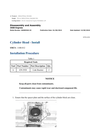
w 1/7(W) Product: ENGINE Model: 3512C ENGINE HZR Configuration: 3512C Petroleum Engine HZR00001-UP Disassembly and Assembly 3516C Generator Set Engines Media Number -M0074278-01 Publication Date -01/09/2018 Date Updated -06/09/2018 i07511232 Cylinder Head - Install SMCS - 1100-012 Installation Procedure Table 1 Required Tools Tool Part Number Part Description Qty A 439-3938 Link Bracket 2 NOTICE Keep all parts clean from contaminants. Contaminants may cause rapid wear and shortened component life. 1. Ensure that the spacer plate and the surface of the cylinder block are clean. https://127.0.0.1/sisweb/sisweb/techdoc/techdoc_print_page.jsp?returnurl=/sisweb/sisw... 2022/4/29
w 2/7(W) Illustration 1 g01053983 2. Install the O-ring seal on dowel (14). Illustration 2 g01053978 NOTICE Ensure that the surface of the spacer plate gasket and the surface of the cylinder block are clean. Do not use a gasket adhesive on these surfaces. 3. Install a new gasket (13) on the dowels in the cylinder block. Illustration 3 g01053977 4. Install spacer plate (12) on the dowels. 5. Check the cylinder liner projection. Refer to Testing and Adjusting, "Cylinder Liner Projection" for the correct procedure. https://127.0.0.1/sisweb/sisweb/techdoc/techdoc_print_page.jsp?returnurl=/sisweb/sisw... 2022/4/29
https://www.ebooklibonline.com Hello dear friend! Thank you very much for reading. Enter the link into your browser. The full manual is available for immediate download. https://www.ebooklibonline.com

