Caterpillar Cat 3512C Industrial Engine (Prefix PE4) Service Repair Manual Instant Download (PE400001 and up)
Please open the website below to get the complete manualnn//
Download Presentation

Please find below an Image/Link to download the presentation.
The content on the website is provided AS IS for your information and personal use only. It may not be sold, licensed, or shared on other websites without obtaining consent from the author. Download presentation by click this link. If you encounter any issues during the download, it is possible that the publisher has removed the file from their server.
E N D
Presentation Transcript
w 1/7(W) Product: INDUSTRIAL ENGINE Model: 3512C INDUSTRIAL ENGINE PE4 Configuration: 3512C Industrial Engine PE400001-UP Disassembly and Assembly 3500 Engines Media Number -RENR9365-35 Publication Date -01/08/2015 Date Updated -14/09/2018 i07511232 Cylinder Head - Install SMCS - 1100-012 Installation Procedure Table 1 Required Tools Tool Part Number Part Description Qty A 439-3938 Link Bracket 2 NOTICE Keep all parts clean from contaminants. Contaminants may cause rapid wear and shortened component life. 1. Ensure that the spacer plate and the surface of the cylinder block are clean. https://127.0.0.1/sisweb/sisweb/techdoc/techdoc_print_page.jsp?returnurl=/sisweb/sisw... 2022/4/27
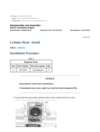
w 2/7(W) Illustration 1 g01053983 2. Install the O-ring seal on dowel (14). Illustration 2 g01053978 NOTICE Ensure that the surface of the spacer plate gasket and the surface of the cylinder block are clean. Do not use a gasket adhesive on these surfaces. 3. Install a new gasket (13) on the dowels in the cylinder block. Illustration 3 g01053977 4. Install spacer plate (12) on the dowels. 5. Check the cylinder liner projection. Refer to Testing and Adjusting, "Cylinder Liner Projection" for the correct procedure. https://127.0.0.1/sisweb/sisweb/techdoc/techdoc_print_page.jsp?returnurl=/sisweb/sisw... 2022/4/27
w 3/7(W) Illustration 4 g01053975 6. Install new seals (9) and (10) in the spacer plate. 7. Install a new O-ring seal (11) on the dowel. 8. Ensure that the bottom of the cylinder head assembly is thoroughly clean. Illustration 5 g00618255 NOTICE The plug for Location (C) MUST be installed in the cylinder head. 9. Install Tooling (A) into the threaded holes for the valve cover base in the cylinder head. Attach a suitable lifting device to Tooling (A). https://127.0.0.1/sisweb/sisweb/techdoc/techdoc_print_page.jsp?returnurl=/sisweb/sisw... 2022/4/27
https://www.ebooklibonline.com Hello dear friend! Thank you very much for reading. Enter the link into your browser. The full manual is available for immediate download. https://www.ebooklibonline.com
w 4/7(W) Illustration 6 g01053935 Note: The weight of cylinder head assembly (7) is approximately 47 kg (104 lb). 10. Install a new head gasket (8). Lift cylinder head assembly (7) into position on the cylinder block. Install bolts (6) and (1) according to the instructions in Step 11, Step 12, or Step 13. Note: Only 216 mm (8.5 inch) bolts (6) can be used for the following torque procedures. Note: Refer to Specifications, "Cylinder Head". Illustration 7 g06344184 11. Tightening sequence with 362-8264 Cylinder Head Gasket (MLS) and 519-7297 Spacer Plate (Iron). https://127.0.0.1/sisweb/sisweb/techdoc/techdoc_print_page.jsp?returnurl=/sisweb/sisw... 2022/4/27
w 5/7(W) Note: Refer to Illustration 7 for the correct tightening sequence. a. Coat the threads of the bolts with clean engine oil. b. Tighten bolt (1) through bolt (8) to a torque of 30 5 N m (22 4 lb ft). c. Tighten bolt (1) through bolt (8) to a torque of 145 15 N m (107 11 lb ft). d. Tighten bolt (1) through bolt (8) to a torque of 145 15 N m (107 11 lb ft). e. Turn bolt (1) through bolt (8) an angle of 180 5 degrees. f. Tighten bolts (9) and (10) to a torque of 55 10 N m (40 7 lb ft). Illustration 8 g06344184 12. Tightening sequence with 362-8264 Cylinder Head Gasket (MLS) and 110-6994 Spacer Plate (Aluminum) or 362-9677 Spacer Plate (Aluminum). Note: Refer to Illustration 8 for the correct tightening sequence. a. Coat the threads of the bolts with clean engine oil. b. Tighten bolt (1) through bolt (8) to a torque of 30 5 N m (22 4 lb ft). c. Tighten bolt (1) through bolt (8) to a torque of 100 15 N m (75 11 lb ft). d. Tighten bolt (1) through bolt (8) to a torque of 450 15 N m (332 11 lb ft). e. Loosen bolt (1) through bolt (8) an angle of 90 degrees. f. Tighten bolt (1) through bolt (8) to a torque of 490 15 N m (361 11 lb ft). g. Tighten bolt (9) and bolt (10) to a torque of 55 10 N m (40 7 lb ft). https://127.0.0.1/sisweb/sisweb/techdoc/techdoc_print_page.jsp?returnurl=/sisweb/sisw... 2022/4/27
w 6/7(W) Illustration 9 g06344229 13. Tightening sequence with 110-6991 Cylinder Head Gasket (Cellulose) and 110-6994 Spacer Plate (Aluminum) or 362-9677 Spacer Plate (Aluminum). Note: The cellulose head gasket cannot be used with an iron spacer plate. Note: Refer to Illustration 9 for the correct tightening sequence. a. Tighten bolt (1) through bolt (8) to a torque of 30 5 N m (22 4 lb ft). b. Tighten bolt (1) through bolt (8) to a torque of 200 15 N m (148 11 lb ft). c. Tighten bolt (1) through bolt (8) again to a torque of 200 15 N m (148 11 lb ft). d. Turn bolt (1) through bolt (8) to an angle of 180 degrees. e. Tighten bolt (9) and bolt (10) to a torque of 55 10 N m (41 7 lb ft). 14. Remove Tooling (A) from the cylinder head. Illustration 10 g01053859 https://127.0.0.1/sisweb/sisweb/techdoc/techdoc_print_page.jsp?returnurl=/sisweb/sisw... 2022/4/27
w 7/7(W) 15. Install four bolts (4) (not shown) on exhaust tube assembly and install four bolts (5) (not shown) on inlet tube assembly. Illustration 11 g01053958 16. Position tube (3). Install bolts (2). 17. Fill the cooling system. Refer to Operation and Maintenance Manual, "Cooling System Coolant - Change". End By: a. Install the valve cover base. https://127.0.0.1/sisweb/sisweb/techdoc/techdoc_print_page.jsp?returnurl=/sisweb/sisw... 2022/4/27
w 4/7(W) Removal Procedure Table 1 Required Tools Tool Part Number Part Description Qty A 241-0124 Valve Spring Compressor 1 B 4C-9496 Spring Tester 1 Start By: a. Remove the rocker shaft and pushrods. Refer to Disassembly and Assembly, "Rocker Shaft and Pushrod - Remove". NOTICE Keep all parts clean from contaminants. Contaminants may cause rapid wear and shortened component life. Note: Place the piston at the top of the compression stroke (TC). Remove the valve springs for that cylinder. If the valves fall into the cylinder liner, then the cylinder head must be removed. 1. Position the No. 1 piston at the top center of the compression stroke. Refer to Testing and Adjusting, "Finding Top Center Position for No. 1 Piston". https://127.0.0.1/sisweb/sisweb/techdoc/techdoc_print_page.jsp?returnurl=/sisweb/sisw... 2022/4/27
w 5/7(W) Illustration 1 g01133502 Personal injury can result from being struck by parts propelled by a released spring force. Make sure to wear all necessary protective equipment. Follow the recommended procedure and use all recommended tooling to release the spring force. 2. Install Tooling (A) on valve mechanism cover base (6). 3. Use Tooling (A) to compress inner valve spring (3) and outer valve spring (4). Remove valve spring keepers (1) from the valve. 4. Carefully remove Tooling (A). 5. Remove valve rotator (2), inner valve spring (3), and outer valve spring (4). 6. Remove washer (5) from the exhaust valve guide. Note: Washers are not installed on the inlet valve guide. 7. Use Tooling (B) to check the valve springs (spring force). Refer to Specifications, "Cylinder Head Valves" for additional information on the valve springs. Installation Procedure Table 2 Required Tools Tool Part Number Part Description Qty A 241-0124 Valve Spring Compressor 1 NOTICE Keep all parts clean from contaminants. Contaminants may cause rapid wear and shortened component life. 1. Lubricate the valve stems with clean engine oil. https://127.0.0.1/sisweb/sisweb/techdoc/techdoc_print_page.jsp?returnurl=/sisweb/sisw... 2022/4/27
Suggest: For more complete manuals. Please go to the home page. https://www.ebooklibonline.com If the above button click is invalid. Please download this document first, and then click the above link to download the complete manual. Thank you so much for reading
w 6/7(W) Illustration 2 g01133502 Improper assembly of parts that are spring loaded can cause bodily injury. To prevent possible injury, follow the established assembly procedure and wear protective equipment. 2. Position washer (5), inner valve spring (3), and outer valve spring (4) on the exhaust valve guide. 3. Position inner valve spring (3) and outer valve spring (4) on the inlet valve guide. Note: Washer (5) is not installed on the inlet valve guides. 4. Position valve rotator (2) on the valve stem. 5. Install Tooling (A) on valve mechanism cover base (6). 6. Use Tooling (A) to compress inner valve spring (3) and outer valve spring (4). Install valve spring keepers (1) on the valve. Ensure that the valve spring keepers are properly installed. The valve spring keepers can be thrown from the valve when the valve spring compressor is released. Ensure that the valve spring keepers are properly installed on the valve stem. To help prevent personal injury, https://127.0.0.1/sisweb/sisweb/techdoc/techdoc_print_page.jsp?returnurl=/sisweb/sisw... 2022/4/27
w 7/7(W) keep away from the front of the valve spring keepers and valve springs during the installation of the valves. 7. Carefully remove Tooling (A). End By: a. Install the rocker shaft and pushrods. Refer to Disassembly and Assembly, "Rocker Shaft and Pushrod - Install". https://127.0.0.1/sisweb/sisweb/techdoc/techdoc_print_page.jsp?returnurl=/sisweb/sisw... 2022/4/27
https://www.ebooklibonline.com Hello dear friend! Thank you very much for reading. Enter the link into your browser. The full manual is available for immediate download. https://www.ebooklibonline.com


