Caterpillar Cat 215 EXCAVATOR (Prefix 96L) Service Repair Manual Instant Download (96L00787 and up)
Please open the website below to get the complete manualnn//
Download Presentation

Please find below an Image/Link to download the presentation.
The content on the website is provided AS IS for your information and personal use only. It may not be sold, licensed, or shared on other websites without obtaining consent from the author. Download presentation by click this link. If you encounter any issues during the download, it is possible that the publisher has removed the file from their server.
E N D
Presentation Transcript
215 EXCAVATOR 96L00787-UP (MACHINE) POWERED BY 3304 ENGINE(SEB... 1/1 Product: EXCAVATOR Model: 215 EXCAVATOR 96L Configuration: 215 EXCAVATOR 96L00787-UP (MACHINE) POWERED BY 3304 ENGINE Disassembly and Assembly SUPPLEMENT FOR 3304 & 3306 ENGINES WITH SPACER PLATE Media Number -SENR7883-00 Publication Date -01/12/1978 Date Updated -10/02/2002 Introduction The specifications given in this book are on the basis of information available at the time it was written. The specifications torques, pressures of operation, measurements, adjustments and other items can change at any time. These changes can effect the service given to the product. Get the complete and most current information before you start any job. Caterpillar Dealers have the most current information which is available. For a list of the most current modules and form numbers available for each Service Manual, see the SERVICE MANUAL CONTENTS MICROFICHE REG1139F. When the words "use again" are in the description, the specification given can be used to determine if a part can be used again. If the part is equal to or within the specification given, use the part again. When the word "permissible" is in the description, the specification given is the "maximum or minimum" tolerance permitted before adjustment, repair and/or new parts are needed. A comparison can be made between the measurements of a worn part, and the specifications of a new part to find the amount of wear. A part that is worn can be safe to use if an estimate of the remainder of its service life is good. If a short service life is expected, replace the part. https://127.0.0.1/sisweb/sisweb/techdoc/techdoc_print_page.jsp?returnurl=/sis... 2021/10/9
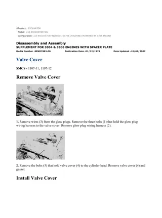
215 EXCAVATOR 96L00787-UP (MACHINE) POWERED BY 3304 ENGINE(SEB... 1/2 Product: EXCAVATOR Model: 215 EXCAVATOR 96L Configuration: 215 EXCAVATOR 96L00787-UP (MACHINE) POWERED BY 3304 ENGINE Disassembly and Assembly SUPPLEMENT FOR 3304 & 3306 ENGINES WITH SPACER PLATE Media Number -SENR7883-00 Publication Date -01/12/1978 Date Updated -10/02/2002 Valve Cover SMCS - 1107-11; 1107-12 Remove Valve Cover 1. Remove wires (3) from the glow plugs. Remove the three bolts (1) that hold the glow plug wiring harness to the valve cover. Remove glow plug wiring harness (2). 2. Remove the bolts (5) that hold valve cover (4) to the cylinder head. Remove valve cover (4) and gasket. Install Valve Cover https://127.0.0.1/sisweb/sisweb/techdoc/techdoc_print_page.jsp?returnurl=/sis... 2021/10/9
215 EXCAVATOR 96L00787-UP (MACHINE) POWERED BY 3304 ENGINE(SEB... 2/2 1. Put 5H2471 Cement on the face of valve cover (1) and the top side of the valve cover gasket. Put the valve cover in position on the cylinder head. Install the bolts that hold it. Tighten the bolts in number sequence to a torque of 96 24 lb. in. (10.9 2.8 N m). 2. Install glow plug wiring harness (2) with the three bolts that hold it. Install wires (3) on the glow plugs. https://127.0.0.1/sisweb/sisweb/techdoc/techdoc_print_page.jsp?returnurl=/sis... 2021/10/9
https://www.ebooklibonline.com Hello dear friend! Thank you very much for reading. Enter the link into your browser. The full manual is available for immediate download. https://www.ebooklibonline.com
215 EXCAVATOR 96L00787-UP (MACHINE) POWERED BY 3304 ENGINE(SEB... 1/2 Product: EXCAVATOR Model: 215 EXCAVATOR 96L Configuration: 215 EXCAVATOR 96L00787-UP (MACHINE) POWERED BY 3304 ENGINE Disassembly and Assembly SUPPLEMENT FOR 3304 & 3306 ENGINES WITH SPACER PLATE Media Number -SENR7883-00 Publication Date -01/12/1978 Date Updated -10/02/2002 Rocker Shaft And Push Rods SMCS - 1102; 1208-11 Remove Rocker Shaft And Push Rods start by: a) remove valve cover 1. Loosen adjustment screws (3) to have maximum valve clearance. 2. Remove six bolts (2) and washers that hold the rocker shaft in position. 3. Remove rocker shaft assembly (1). 4. Remove push rods (4). https://127.0.0.1/sisweb/sisweb/techdoc/techdoc_print_page.jsp?returnurl=/sis... 2021/10/9
215 EXCAVATOR 96L00787-UP (MACHINE) POWERED BY 3304 ENGINE(SEB... 2/2 5. Remove O-ring seal (5) from rear support bracket. NOTE: The O-ring seal (5) must be replaced each time the head bolt is removed from the rear support bracket. https://127.0.0.1/sisweb/sisweb/techdoc/techdoc_print_page.jsp?returnurl=/sis... 2021/10/9
215 EXCAVATOR 96L00787-UP (MACHINE) POWERED BY 3304 ENGINE(SEB... 1/2 Product: EXCAVATOR Model: 215 EXCAVATOR 96L Configuration: 215 EXCAVATOR 96L00787-UP (MACHINE) POWERED BY 3304 ENGINE Disassembly and Assembly SUPPLEMENT FOR 3304 & 3306 ENGINES WITH SPACER PLATE Media Number -SENR7883-00 Publication Date -01/12/1978 Date Updated -10/02/2002 Rocker Shaft And Push Rods SMCS - 1102; 1208-12 Install Rocker Shaft And Push Rods 1. Install a new O-ring seal in the rear support bracket of rocker shaft. 2. Install push rods (1). 3. Put rocker shaft (2) in position on the cylinder head. NOTE: Make sure dowels (3) are in alignment at both ends of the rocker shaft. 4. Put 5P3931 Anti-Seize Compound on the threads of the bolts that hold the rocker shaft in position. Install the six bolts and washers. https://127.0.0.1/sisweb/sisweb/techdoc/techdoc_print_page.jsp?returnurl=/sis... 2021/10/9
215 EXCAVATOR 96L00787-UP (MACHINE) POWERED BY 3304 ENGINE(SEB... 2/2 5. Tighten all bolts (4), (5), (6), (7), (8), (9) in number sequence to a torque of 115 lb. ft. (155 N m). Tighten bolts again in number sequence to a torque of 185 13 lb.ft. (250 17 N m). Last, tighten the bolts again (hand turn only) in number sequence to a torque of 185 13 lb. ft. (250 17 N m). 6. Make adjustments until the intake valve clearance is .015 in. (0.38 mm) and the exhaust valve clearance is .025 in. (0.64 mm). 7. Check the torque on all of the cylinder head bolts. See CYLINDER HEAD in SPECIFICATIONS, for the correct procedure to tighten the cylinder head bolts. end by: a) install valve cover https://127.0.0.1/sisweb/sisweb/techdoc/techdoc_print_page.jsp?returnurl=/sis... 2021/10/9
215 EXCAVATOR 96L00787-UP (MACHINE) POWERED BY 3304 ENGINE(SEB... 1/3 Product: EXCAVATOR Model: 215 EXCAVATOR 96L Configuration: 215 EXCAVATOR 96L00787-UP (MACHINE) POWERED BY 3304 ENGINE Disassembly and Assembly SUPPLEMENT FOR 3304 & 3306 ENGINES WITH SPACER PLATE Media Number -SENR7883-00 Publication Date -01/12/1978 Date Updated -10/02/2002 Rocker Shaft SMCS - 1102-15; 1102-16 Disassemble Rocker Shaft start by: a) remove rocker shaft and push rods 1. Remove O-ring seal (1) from the rear support bracket. NOTE: A replacement of the O-ring seal must be made each time the head bolt is removed from the rear support bracket. 2. Remove retainer ring (6), washer (5), spring (4) and washer (3) from each end of rocker shaft. Remove rocker arm (2). https://127.0.0.1/sisweb/sisweb/techdoc/techdoc_print_page.jsp?returnurl=/sis... 2021/10/9
215 EXCAVATOR 96L00787-UP (MACHINE) POWERED BY 3304 ENGINE(SEB... 2/3 3. Remove pin from rear support bracket with a hammer and punch. Remove rear support bracket (7) from shaft. 4. Remove remainder of rocker arms, springs, washers and brackets. 5. Remove plugs from each end of the shaft if necessary. Assemble Rocker Shaft 1. Install rocker arms (5), brackets (1), washers (4) and springs (2) on the rocker shaft. 2. Install rear support bracket (6) on rocker shaft. Make sure hole in rear support bracket is in alignment with hole in rocker shaft. 3. Put pin (3) in position in the bracket. 4. Install pin (3) through bracket and shaft with a hammer. 5. Pin (3) must extend .378 in. (9.60 mm) above the bracket. https://127.0.0.1/sisweb/sisweb/techdoc/techdoc_print_page.jsp?returnurl=/sis... 2021/10/9
215 EXCAVATOR 96L00787-UP (MACHINE) POWERED BY 3304 ENGINE(SEB... 3/3 6. Install O-ring seal (7) in the rear support bracket. Install rocker arm (8), washer, spring, washer and retainer ring on the rocker shaft. 7. Install the plugs in each end of the rocker shaft if they were removed. end by: a) install rocker shaft and push rods https://127.0.0.1/sisweb/sisweb/techdoc/techdoc_print_page.jsp?returnurl=/sis... 2021/10/9
215 EXCAVATOR 96L00787-UP (MACHINE) POWERED BY 3304 ENGINE(SEB... 1/2 Product: EXCAVATOR Model: 215 EXCAVATOR 96L Configuration: 215 EXCAVATOR 96L00787-UP (MACHINE) POWERED BY 3304 ENGINE Disassembly and Assembly SUPPLEMENT FOR 3304 & 3306 ENGINES WITH SPACER PLATE Media Number -SENR7883-00 Publication Date -01/12/1978 Date Updated -10/02/2002 Spacer Plate SMCS - 1221-11; 1221-12 Remove Spacer Plate start by: a) remove cylinder head 1. Remove large and small water ferrules (1) from the spacer plate. 2. Remove O-ring seal (2) from the hollow dowel. 3. Remove spacer plate (3). 4. Remove O-ring seal (4), then remove spacer plate gasket (5) from the cylinder block. Install Spacer Plate 1. Thoroughly clean the spacer plate and cylinder block surface. https://127.0.0.1/sisweb/sisweb/techdoc/techdoc_print_page.jsp?returnurl=/sis... 2021/10/9
215 EXCAVATOR 96L00787-UP (MACHINE) POWERED BY 3304 ENGINE(SEB... 2/2 2. Install a new spacer plate gasket (3). Install a new O-ring seal (2) on the hollow dowel. 3. Install spacer plate (1). NOTICE Both surfaces of spacer plate, top of cylinder block and both sides of spacer plate gasket must be clean and dry. Do not use any gasket adhesives or other substances on these surfaces. 4. Install a new O-ring seal (5) on the hollow dowel. 5. Install new large and small water ferrules (4) in the spacer plates. 6. Check cylinder liner projection. See INSTALL CYLINDER LINERS. end by: a) install cylinder head https://127.0.0.1/sisweb/sisweb/techdoc/techdoc_print_page.jsp?returnurl=/sis... 2021/10/9
215 EXCAVATOR 96L00787-UP (MACHINE) POWERED BY 3304 ENGINE(SEB... 1/4 Product: EXCAVATOR Model: 215 EXCAVATOR 96L Configuration: 215 EXCAVATOR 96L00787-UP (MACHINE) POWERED BY 3304 ENGINE Disassembly and Assembly SUPPLEMENT FOR 3304 & 3306 ENGINES WITH SPACER PLATE Media Number -SENR7883-00 Publication Date -01/12/1978 Date Updated -10/02/2002 Cylinder Liners SMCS - 1216-11; 1216-12 Remove Cylinder Liners start by: a) remove pistons 1. Remove the coolant from the cylinder block. 2. Put covers on journals of crankshaft for protection from dirt or water. 3. Remove cylinder liners (1) with tooling (A). https://127.0.0.1/sisweb/sisweb/techdoc/techdoc_print_page.jsp?returnurl=/sis... 2021/10/9
215 EXCAVATOR 96L00787-UP (MACHINE) POWERED BY 3304 ENGINE(SEB... 2/4 Install Cylinder Liners 1. Clean the cylinder liners (3) and the liner bores in the cylinder block. 2. Install the cylinder liners in the block without the O-ring seals or filler bands. 3. Check the cylinder liner projection as follows: a) Install the S1589 Bolts (2) and 1S379 Washers of tooling (B) on the cylinder block next to each liner. Tighten the bolts evenly, in four steps: 10 lb. ft. (14 N m), 25 lb. ft. (35 N m), 50 lb. ft. (70 N m) and 70 lb. ft. (95 N m). b) Put adapter plate on top of the liner and install the remainder of tooling (B). Tighten the 1D4595 Bolts (1) evenly in four steps: 5 lb. ft. (7 N m), 15 lb. ft. (20 N m), 25 lb. ft. (35 N m) and 50 lb. ft. (70 N m). c) Check to be sure the distance from the bottom edge of the crossbar to the top of the cylinder block is the same on both sides of the liner. d) Check the cylinder liner projection with tool group (C) at four locations around the liner. https://127.0.0.1/sisweb/sisweb/techdoc/techdoc_print_page.jsp?returnurl=/sis... 2021/10/9
215 EXCAVATOR 96L00787-UP (MACHINE) POWERED BY 3304 ENGINE(SEB... 3/4 e) Liner projection must be .0013 to .0069 in. (0.033 to 0.175 mm). Measurements on the same liner must not be different by more than .002 in. (0.05 mm). Average measurements between liners next to each other must not be different by more than .002 in. (0.05 mm). NOTE: If the liner is turned in the bore, it can make a difference in the liner projection. 4. If the liner projection is not .0013 to .0069 in. (0.033 to 0.175 mm), check the thickness of the following parts: spacer plate, spacer plate gasket and cylinder liner flange. The thickness of the spacer plate must be .3925 .0010 in. (9.970 0.025 mm). The thickness of the spacer plate gasket must be .0082 .0010 in. (0.208 0.025 mm). The thickness of the cylinder liner flange must be .4048 .0008 in. (10.282 0.020 mm). NOTE: If the liner projection changes from point to point around the liner, turn the liner to a new position in the bore. If the liner projection is still not to specifications, move the liner to a different bore. 5. When the cylinder projection is correct, put a mark on the liner and block so the liner can be installed in the same position from which it was removed. NOTE: Cylinder liner projection can be adjusted by the removal of material from (machining) the contact face of the cylinder block with the use of the 8S3140 Cylinder Block Counterboring Tool Arrangement. Machine to a minimum depth of .030 in. (0.76 mm) and to a maximum depth of .045 in. (1.14 mm). The instructions for the use of the tool group are in Special Instruction Form No. FM055228. Shims are available for the adjustment of the liner projection. See CYLINDER LINER PROJECTION in TESTING AND ADJUSTING for the shim thickness and part number. 6. Remove tooling (B) and (C). Remove the liner. 7. Put liquid soap on bottom liner bore in block, on grooves in lower liner and on O-ring seals (4). Install O-ring seals on the liner. 8. Put filler band (5) in clean SAE 30 oil for a moment and install on liner. Install cylinder liner immediately in the cylinder block (before expansion of filler band). https://127.0.0.1/sisweb/sisweb/techdoc/techdoc_print_page.jsp?returnurl=/sis... 2021/10/9
215 EXCAVATOR 96L00787-UP (MACHINE) POWERED BY 3304 ENGINE(SEB... 4/4 9. Make sure the mark on liner is in alignment with the mark on the block. Use tooling (A) to push the liner into position. 10. Do Steps 5 through 9 for the remainder of the cylinder liners. end by: a) install pistons https://127.0.0.1/sisweb/sisweb/techdoc/techdoc_print_page.jsp?returnurl=/sis... 2021/10/9
215 EXCAVATOR 96L00787-UP (MACHINE) POWERED BY 3304 ENGINE(SEB... 1/4 Product: EXCAVATOR Model: 215 EXCAVATOR 96L Configuration: 215 EXCAVATOR 96L00787-UP (MACHINE) POWERED BY 3304 ENGINE Disassembly and Assembly SUPPLEMENT FOR 3304 & 3306 ENGINES WITH SPACER PLATE Media Number -SENR7883-00 Publication Date -01/12/1978 Date Updated -10/02/2002 Cylinder Head SMCS - 1100-11; 1100-12 Remove Cylinder Head start by: a) remove rocker shaft and push rods b) remove fuel injection lines 1. Remove two bolts (1) from the top of the water pump. Loosen two bolts (2) in the water pump. 2. Remove oil supply line (3) from the turbocharger. Remove oil return line (4) from the turbocharger. https://127.0.0.1/sisweb/sisweb/techdoc/techdoc_print_page.jsp?returnurl=/sis... 2021/10/9
215 EXCAVATOR 96L00787-UP (MACHINE) POWERED BY 3304 ENGINE(SEB... 2/4 3. Remove the bolts (5) that hold the cylinder head to the cylinder block. 4. Fasten a hoist to the cylinder head assembly (6). Remove the cylinder head assembly from the block. Weight of the assembly is 290 lb. (131 kg). Remove O-ring seal from hollow dowel. Remove cylinder head gasket (7) and water ferrules. NOTICE Do not put the cylinder head down on a flat surface. This can cause damage to the fuel injection valves. NOTE: Always install a new gasket between spacer plate and cylinder block before cylinder head is installed. See REMOVE SPACER PLATE. Install Cylinder Head 1. Thoroughly clean the spacer plate and bottom surface of the cylinder head. Install a new head gasket (2), water ferrules (1) and O-ring seal (3) on the hollow dowel. https://127.0.0.1/sisweb/sisweb/techdoc/techdoc_print_page.jsp?returnurl=/sis... 2021/10/9
215 EXCAVATOR 96L00787-UP (MACHINE) POWERED BY 3304 ENGINE(SEB... 3/4 NOTE: Be sure a new gasket has been installed between spacer plate and cylinder block. See INSTALL SPACER PLATE. 2. Fasten a hoist and install the cylinder head assembly (4) on the cylinder block. 3. Install the push rods and put the rocker shaft in position on the cylinder head. Put 5P3931 Anti- Seize Compound on the threads of the cylinder head and rocker shaft bolts. Install the bolts and washers and tighten the bolts as follows: 1. Tighten all bolts in number sequence to a torque of 115 lb. ft. (155 N m). 2. Again tighten all bolts in number sequence to a torque of 185 13 lb. ft. (250 17 N m). 3. Again tighten all bolts in number sequence (hand torque only) to a torque of 185 13 lb. ft. (250 17 N m). 4. Tighten all bolts in letter sequence to a torque of 22 lb. ft. (30 N m). 5. Again tighten all bolts in letter sequence to a torque of 32 5 lb. ft. (43 7 N m). 6. Again tighten all bolts in letter sequence to a torque of 32 5 lb. ft. (43 7 N m). 4. Make adjustment of valves to have a clearance of .015 in. (0.38 mm) for intake and .025 in. (0.64 mm) for exhaust. 5. Install oil return line (6) on the turbocharger. 6. Install oil supply line (5) on the turbocharger. https://127.0.0.1/sisweb/sisweb/techdoc/techdoc_print_page.jsp?returnurl=/sis... 2021/10/9
215 EXCAVATOR 96L00787-UP (MACHINE) POWERED BY 3304 ENGINE(SEB... 4/4 7. Tighten the two bolts (8) in the water pump. 8. Install the two bolts (7) that hold the water pump to the cylinder head. end by: a) install fuel injection lines https://127.0.0.1/sisweb/sisweb/techdoc/techdoc_print_page.jsp?returnurl=/sis... 2021/10/9
Suggest: For more complete manuals. Please go to the home page. https://www.ebooklibonline.com If the above button click is invalid. Please download this document first, and then click the above link to download the complete manual. Thank you so much for reading
215 EXCAVATOR 96L00787-UP (MACHINE) POWERED BY 3304 ENGINE(SEB... 1/2 Product: EXCAVATOR Model: 215 EXCAVATOR 96L Configuration: 215 EXCAVATOR 96L00787-UP (MACHINE) POWERED BY 3304 ENGINE Disassembly and Assembly 3304 VEHICULAR ENGINE FOR 215 EXCAVATOR Media Number -SENR7426-00 Publication Date -01/03/1977 Date Updated -10/02/2002 Oil Pan SMCS - 1302-11; 1302-12 Remove Oil Pan 1. Remove the oil from the engine. 2. Remove the four bolts that hold the front support to the frame. Loosen engine rear mounting bolts. Put two hydraulic jacks under the front of the engine and lift the engine until a 3" (76.2 mm) spacer (1) can be installed between the frame and the engine front support on each side of the engine. Lower the engine on the spacers. 3. Disconnect oil level gauge (3) from the oil pan. https://127.0.0.1/sisweb/sisweb/techdoc/techdoc_print_page.jsp?returnurl=/sis... 2021/10/9
215 EXCAVATOR 96L00787-UP (MACHINE) POWERED BY 3304 ENGINE(SEB... 2/2 4. Remove twenty-four bolts (2) that hold the oil pan in place and remove oil pan (4). Install Oil Pan 1. Inspect the gasket for the oil pan. Install a new gasket if needed. 2. Put oil pan (2) in position on the engine and install the bolts that hold the oil pan in place. NOTE: Make sure oil gauge tube (1) is in correct position when the oil pan is installed. 3. Connect oil gauge tube (1) to the oil pan. 4. Lift the engine with two hydraulic jacks and remove spacers (3) and (4) from under the front support. Lower the engine to the correct position. Remove the hydraulic jacks. 5. Install the four front support bolts. 6. Tighten the engine rear mounting bolts. 7. Fill the crankcase with oil to the correct level. https://127.0.0.1/sisweb/sisweb/techdoc/techdoc_print_page.jsp?returnurl=/sis... 2021/10/9
https://www.ebooklibonline.com Hello dear friend! Thank you very much for reading. Enter the link into your browser. The full manual is available for immediate download. https://www.ebooklibonline.com

