Caterpillar Cat 215 EXCAVATOR (Prefix 61Z) Service Repair Manual Instant Download (61Z00139 and up)
Please open the website below to get the complete manualnn//
Download Presentation

Please find below an Image/Link to download the presentation.
The content on the website is provided AS IS for your information and personal use only. It may not be sold, licensed, or shared on other websites without obtaining consent from the author. Download presentation by click this link. If you encounter any issues during the download, it is possible that the publisher has removed the file from their server.
E N D
Presentation Transcript
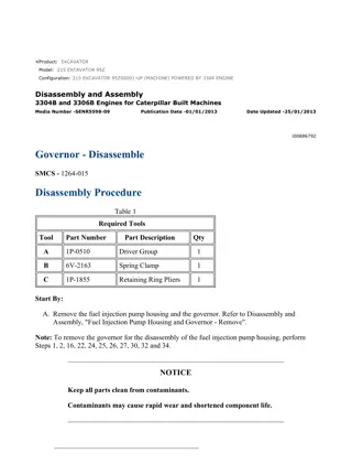
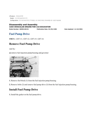
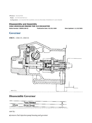
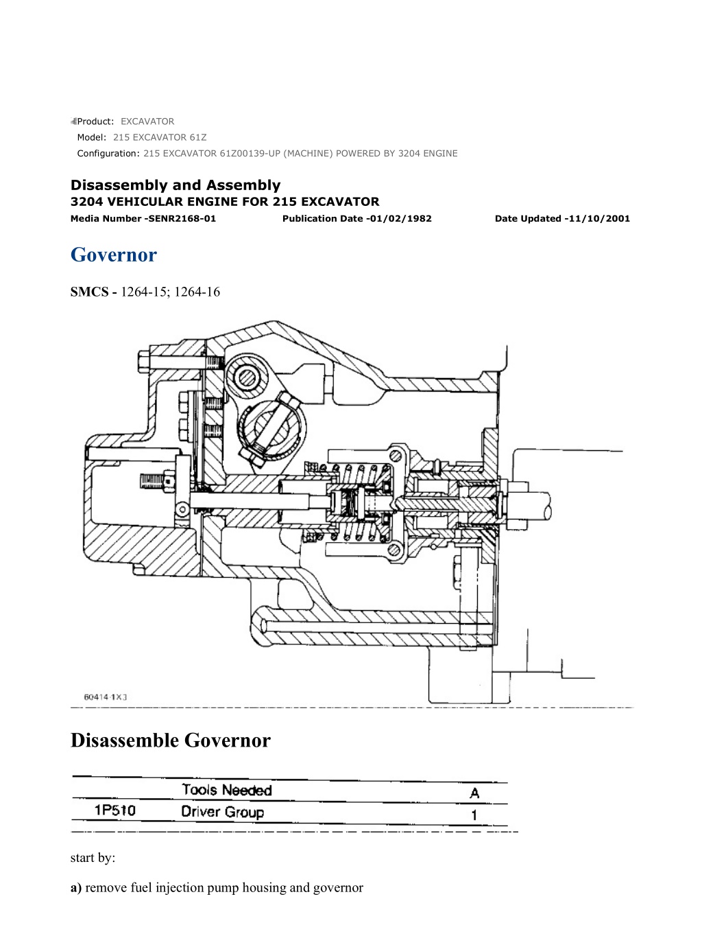
215 EXCAVATOR 61Z00139-UP (MACHINE) POWERED BY 3204 ENGINE(SEB... 1/10 Product: EXCAVATOR Model: 215 EXCAVATOR 61Z Configuration: 215 EXCAVATOR 61Z00139-UP (MACHINE) POWERED BY 3204 ENGINE Disassembly and Assembly 3204 VEHICULAR ENGINE FOR 215 EXCAVATOR Media Number -SENR2168-01 Publication Date -01/02/1982 Date Updated -11/10/2001 Governor SMCS - 1264-15; 1264-16 Disassemble Governor start by: a) remove fuel injection pump housing and governor https://127.0.0.1/sisweb/sisweb/techdoc/techdoc_print_page.jsp?returnurl=/sis... 2021/10/12
215 EXCAVATOR 61Z00139-UP (MACHINE) POWERED BY 3204 ENGINE(SEB... 2/10 NOTE: If it is desired to only remove the governor so the fuel injection pump housing can be disassembled do only Steps 1, 3, 5, 6, 12, and 13. 1. Remove cover (1). 2. Remove lever (2) and the key from the shaft. 3. Remove bolts (3) and cover (4) from the governor housing. 4. Remove O-ring seals (5) from the low and high idle adjustment screws. 5. Remove screw (6) from rack stop collar (7) and remove collar (7). Remove the spring from behind the collar. 6. Remove bolts (8) and remove governor housing (9) from the fuel injection pump housing. https://127.0.0.1/sisweb/sisweb/techdoc/techdoc_print_page.jsp?returnurl=/sis... 2021/10/12
215 EXCAVATOR 61Z00139-UP (MACHINE) POWERED BY 3204 ENGINE(SEB... 3/10 7. Remove high idle adjustment screw (11) and low idle adjustment screw (10) from the governor housing. Remove the high idle adjustment screw first. 8. Remove bolts (12) and torque control (13) from the governor housing. 9. Remove bolt (14) and the lock. Remove shaft (15) and lever assembly (16) from the governor housing. Pin (19) holds spring (17) in compression. Use caution to prevent injury when pin (19) is removed. Release the tension in spring (17) slowly. 10. Remove pin (19), spring (17) and plunger (18) from the lever assembly. https://127.0.0.1/sisweb/sisweb/techdoc/techdoc_print_page.jsp?returnurl=/sis... 2021/10/12
https://www.ebooklibonline.com Hello dear friend! Thank you very much for reading. Enter the link into your browser. The full manual is available for immediate download. https://www.ebooklibonline.com
215 EXCAVATOR 61Z00139-UP (MACHINE) POWERED BY 3204 ENGINE(SEB... 4/10 11. Remove seal (21) from the governor housing. Use tooling (A) to remove the plug and bearings (20) from the governor housing. NOTE: If a replacement of spring guide (22) is necessary see SPECIAL INSTRUCTION Form No. SMHS7356 - USE OF 6V22 TOOL GROUP FOR REPLACEMENT OF GOVERNOR SPRING GUIDE. 12. Remove seat, washer, wave-washers and governor spring (23) from the weight assembly. Remove spring washer (26) from the weight assembly. 13. Remove bolts (24) and the lock that hold weight assembly (25) to the fuel injection pump housing. Pull the weight assembly out and to the side to disengage it from the rack. 14. Remove ring (27) and the dowel under the ring that holds seat (28) in place. 15. Remove seat (28), bolt (29) and spring (30) from the weight assembly. Remove washer (31) from spring (30). https://127.0.0.1/sisweb/sisweb/techdoc/techdoc_print_page.jsp?returnurl=/sis... 2021/10/12
215 EXCAVATOR 61Z00139-UP (MACHINE) POWERED BY 3204 ENGINE(SEB... 5/10 16. Remove guide (32), the two races and bearing from the sleeve. 17. Remove the second dowel (33) that holds sleeve (34) in place and remove the sleeve. 18. Remove valve (37) from the weight assembly and cylinder (35). 19. Remove lock (36) and make a separation of the weight assembly and cylinder (35). 20. Remove sleeve (38) and piston (39) from cylinder (35). Remove the O-ring seal from the sleeve. Assemble Governor NOTE: Put clean oil on all parts before assembly and be sure all oil passages are clear. https://127.0.0.1/sisweb/sisweb/techdoc/techdoc_print_page.jsp?returnurl=/sis... 2021/10/12
215 EXCAVATOR 61Z00139-UP (MACHINE) POWERED BY 3204 ENGINE(SEB... 6/10 1. Install the O-ring seal on sleeve (2). Install piston (1) in sleeve (2). Install sleeve (2) in cylinder (3). 2. Install cylinder (3) in weight assembly (4) and install lock (5) to hold them together. 3. Install valve (7) through the cylinder and install sleeve (6) on the valve with the second hole in the sleeve in alignment with the hold in the valve. Install dowel (8) to hold the sleeve on the valve. 4. Install larger race (9), bearing (10), smaller race (11) and guide (12) on sleeve (8). Put the hole in guide (12) in alignment with the first hole in sleeve (8). https://127.0.0.1/sisweb/sisweb/techdoc/techdoc_print_page.jsp?returnurl=/sis... 2021/10/12
215 EXCAVATOR 61Z00139-UP (MACHINE) POWERED BY 3204 ENGINE(SEB... 7/10 5. Install washer (16) in spring (13). Install bolt (17) in seat (14). Put spring (13) and seat (14) in position on guide (12) with the hole in seat (14) in alignment with the hole in guide (12). Install dowel (18) through seat (14) and guide (12). Install ring (15) on the seat to hold the dowel in place. 6. Install the weight assembly on the fuel injection pump housing with piston (1) engaged over the groove in rack (19). Install lock (20) and the bolts that hold the weight assembly to the fuel injection pump housing. 7. Install spring washer (26) on the bolt as shown. 8. Install spring (25), one wave washer (24), flat washer (23), other wave washer (22) and seat (21) on the bolt as shown. 9. Put plunger (28) and spring (27) in position in lever assembly (30) and install pin (29) to hold the spring and plunger in place. https://127.0.0.1/sisweb/sisweb/techdoc/techdoc_print_page.jsp?returnurl=/sis... 2021/10/12
215 EXCAVATOR 61Z00139-UP (MACHINE) POWERED BY 3204 ENGINE(SEB... 8/10 10. Dimensions (X) and (Y) are controlled by the depths of bearings (32) and (33) in the governor housing. Install bearings (32) and (33) with tooling (A). Install lever assembly (30) and shaft (31) in the governor housing. With lever assembly (30) pushed against bearing (33) on the detent side, the clearance [dimension (Y)] between the guide for the governor spring and lever assembly (30) must be approximately 2.49 mm (.098 in.). Push lever assembly (30) against bearing (32) on the other side. The clearance [dimension (X)] between the guide for the governor spring and lever assembly must be approximately 3.40 mm (.134 in.). If the measurements are not correct, remove the lever assembly and the shaft and move the bearings as necessary to get the correct measurement. After the bearings are installed, there must be approximately .38 mm (.015 in.) end play in the lever assembly. Remove the shaft and lever assembly. 11. Install the plug on the detent side of the governor housing with tooling (A) to a depth of 2.3 0.5 mm (.091 0.20 in.). Install the lip type seal in the opposite side of the governor housing with tooling (A). Install the lip type seal with the lip toward the inside of the governor housing. 12. Put the lever assembly and shaft in position in the governor housing and install the bolt and lock in the lever assembly. 13. Assemble the torque control group as follows: https://127.0.0.1/sisweb/sisweb/techdoc/techdoc_print_page.jsp?returnurl=/sis... 2021/10/12
215 EXCAVATOR 61Z00139-UP (MACHINE) POWERED BY 3204 ENGINE(SEB... 9/10 a) Install lock (35), retainer (36), insulator (37) and retainer (38) on bolts (34) as shown. b) Install contact (39) on bolts (34) as shown. c) Install spring (40), spacer (41), shim (42), bar (43) and insulator (44) on bolts (34) as shown. 14. Install torque control group (45) on the governor housing as shown. Bend the lock to hold the bolts tight. 15. Install low idle adjustment screw (46) first, then high idle adjustment screw (47) in the governor housing. 16. Put the gasket and governor housing (48) in position on the fuel injection pump housing with bolt (17) and the spring seat in alignment with the spring guide in the governor housing. Install the bolts that hold the governor housing to the fuel injection pump housing. 17. Install O-ring seals (49) on the low and high idle adjustment screws. https://127.0.0.1/sisweb/sisweb/techdoc/techdoc_print_page.jsp?returnurl=/sis... 2021/10/12
215 EXCAVATOR 61Z00139-UP (MACHINE) POWERED BY 3204 ENGINE(SE... 10/10 18. Put spring (50) and rack stop collar (51) in position on the bolt in the weight assembly and install the allen screw that holds the rack stop collar in place. 19. Put the gasket and cover in position on the governor housing with dowel (52) in the cover in alignment with notch (53) in the rack stop collar. Install the bolts that hold the cover in place. 20. Install the gasket and cover (54) over the low and high idle adjustment screws. 21. Install the key and lever on shaft (31). end by: a) install fuel injection pump housing and governor b) make an adjustment to the rack and governor (See FUEL RACK SETTING AND GOVERNOR ADJUSTMENTS in TESTING AND ADJUSTING) https://127.0.0.1/sisweb/sisweb/techdoc/techdoc_print_page.jsp?returnurl=/sis... 2021/10/12
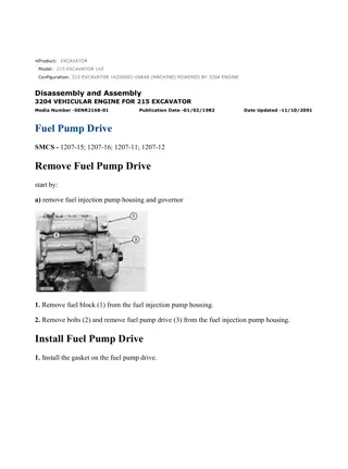
215 EXCAVATOR 61Z00139-UP (MACHINE) POWERED BY 3204 ENGINE(SEB... 1/7 Product: EXCAVATOR Model: 215 EXCAVATOR 61Z Configuration: 215 EXCAVATOR 61Z00139-UP (MACHINE) POWERED BY 3204 ENGINE Disassembly and Assembly 3204 VEHICULAR ENGINE FOR 215 EXCAVATOR Media Number -SENR2168-01 Publication Date -01/02/1982 Date Updated -11/10/2001 Fuel Injection Pumps SMCS - 1251-11; 1251-12; 1251-15; 1251-16 Remove Fuel Injection Pumps start by: a) disassemble governor 1. Remove plug (2) from the fuel injection pump housing. https://127.0.0.1/sisweb/sisweb/techdoc/techdoc_print_page.jsp?returnurl=/sis... 2021/10/12
215 EXCAVATOR 61Z00139-UP (MACHINE) POWERED BY 3204 ENGINE(SEB... 2/7 2. Pull rack (1) toward the governor end of the fuel injection pump housing. Install tool (B) in the pump housing. Hold tool (B) in against the rack and push the rack back toward the drive end of the pump housing until the notch in the rack comes in contact with tool (B). The rack is now in the center position. Install clip (3), part of tooling (A), to hold the rack in the center position against tool (B). NOTICE The rack must be in the center (zero) position before the fuel injection pumps can be removed. Make a note of the location of each fuel injection pump so it can be installed in its original location in the pump housing. 3. Remove the cap and soft washer from the top of the fuel injection pump. 4. Install tool (C) and remove bushing (4) and the O-ring seal below the bushing. 5. Install tool (D) on bonnet (5) of the fuel injection pump and remove the fuel injection pump from the pump housing. https://127.0.0.1/sisweb/sisweb/techdoc/techdoc_print_page.jsp?returnurl=/sis... 2021/10/12
215 EXCAVATOR 61Z00139-UP (MACHINE) POWERED BY 3204 ENGINE(SEB... 3/7 Install Fuel Injection Pumps NOTICE The rack must be in the center (zero) position before the fuel injection pumps can be installed. See Step 2 of the fuel injection pump removal procedure to put the rack in the center position. 1. With the rack in the center position, install the fuel injection pumps as follows: a) Turn the camshaft until the lobe of the camshaft is down for the pump to be installed. b) Install tool (D) on the pump. c) Put the groove (1) in the barrel in alignment with the groove (2) in the pump gear segment. Put the pump in position so the grooves are in alignment with the guide pins in the housing and lifter. Install the pump in its correct position in the housing. https://127.0.0.1/sisweb/sisweb/techdoc/techdoc_print_page.jsp?returnurl=/sis... 2021/10/12
215 EXCAVATOR 61Z00139-UP (MACHINE) POWERED BY 3204 ENGINE(SEB... 4/7 d) Install the O-ring seal and bushing (3) over the bonnet. Install tool (C) on the bonnet and push down on tool (D). Tighten bushing (3) by hand until the bushing is even with the top of the housing. If the installation of the bushing can not be made this far by hand, remove it. Remove the pump, put the parts in alignment again and install the bushing again. NOTICE If installation of pump is correct, the bushing can be tightened by hand until it is even with the face of the pump housing. The fuel injection pump, the housing or the lifter will be damaged if force is used to install the bushing until it is even with the face of the pump housing. e) Check the rack travel after each pump is installed as follows: Move the clamp, part of tooling (A), away from the end of the rack and remove timing pin (B) from the fuel injection pump housing. Install tooling (A) and (E) on the pump housing as shown to measure rack movement. Hold rack (4) against the stem in tool (E) when the measurement is made. The total rack movement must be 20.32 mm (.800 in.). If the rack can not be moved this distance, the pump gear segment is not in the correct position and the pump must be removed and installed again. https://127.0.0.1/sisweb/sisweb/techdoc/techdoc_print_page.jsp?returnurl=/sis... 2021/10/12
215 EXCAVATOR 61Z00139-UP (MACHINE) POWERED BY 3204 ENGINE(SEB... 5/7 2. After all the fuel injection pumps are installed, remove tooling (A) and (E). Install the plug in the hole for timing pin (B). Use tool (C) to tighten bushing (3) to a torque of 205 14 N m (150 10 lb.ft.). Remove tool (C). Install the soft washers and protection caps for the fuel injection pumps. end by: a) assemble governor b) install fuel injection pump housing and governor c) adjust the governor and set the rack (See GOVERNOR ADJUSTMENTS and FUEL RACK SETTING in TESTING AND ADJUSTING) Disassemble Fuel Injection Pumps start by: a) remove fuel injection pumps NOTICE Be careful when the fuel injection pumps are disassembled. Do not damage the surfaces of the plungers, barrels and bonnets. Any scratches will cause leakage inside the fuel injection pump. The plunger and barrel for each pump are made as a set. Do not put the plunger of one pump in the barrel of another pump. The check assemblies are made as a set. Do not mix the parts of the different check assemblies. If one part has wear, install a complete new pump assembly. Be careful when the plunger is put into the bore of the barrel. 1. Remove ring (1) and make a separation of bonnet (2) and barrel (3). https://127.0.0.1/sisweb/sisweb/techdoc/techdoc_print_page.jsp?returnurl=/sis... 2021/10/12
215 EXCAVATOR 61Z00139-UP (MACHINE) POWERED BY 3204 ENGINE(SEB... 6/7 2. Remove spring (4) and check assembly (5) from the bonnet. 3. Remove plunger (8) and washer (7) as a unit from spring (6) and the barrel. Remove washer (7) from the plunger. Remove spring (6) from the barrel. NOTICE Do not remove the gear from the plunger. The gear and plunger are assembled and adjusted at the factory. Assemble Fuel Injection Pumps NOTICE Put clean fuel oil on all parts during assembly. 1. Install spring (2) on barrel (1). Install washer (3) on plunger (4) with the flat side toward the gear. Install plunger (4) in barrel (1) and engage washer (3) in spring (2). 2. Install spring (5) and check assembly (6) in bonnet (7). https://127.0.0.1/sisweb/sisweb/techdoc/techdoc_print_page.jsp?returnurl=/sis... 2021/10/12
215 EXCAVATOR 61Z00139-UP (MACHINE) POWERED BY 3204 ENGINE(SEB... 7/7 NOTICE Do not slide bonnet (7) across the face of barrel (1) when ring (8) is installed. The check assembly in the bonnet can put scratches in the face of barrel (1). 3. Put bonnet (7) in position on barrel (1) and install ring (8) to hold the bonnet and barrel together. end by: a) install fuel injection pumps https://127.0.0.1/sisweb/sisweb/techdoc/techdoc_print_page.jsp?returnurl=/sis... 2021/10/12
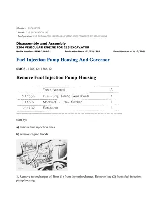
215 EXCAVATOR 61Z00139-UP (MACHINE) POWERED BY 3204 ENGINE(SEB... 1/6 Product: EXCAVATOR Model: 215 EXCAVATOR 61Z Configuration: 215 EXCAVATOR 61Z00139-UP (MACHINE) POWERED BY 3204 ENGINE Disassembly and Assembly 3204 VEHICULAR ENGINE FOR 215 EXCAVATOR Media Number -SENR2168-01 Publication Date -01/02/1982 Date Updated -11/10/2001 Fuel Injection Pump Housing SMCS - 1253-11; 1253-12 Disassemble Fuel Injection Pump Housing start by: a) remove fuel injection pumps 1. Remove elbow (1) and the plate (orifice) under the elbow. 2. Remove rack (2) from the fuel injection pump housing. https://127.0.0.1/sisweb/sisweb/techdoc/techdoc_print_page.jsp?returnurl=/sis... 2021/10/12
215 EXCAVATOR 61Z00139-UP (MACHINE) POWERED BY 3204 ENGINE(SEB... 2/6 NOTE: Spacers (3) are different thickness and are used to make a setting of the injection timing between cylinders. Spacers (3) and lifters (4) must be installed in the same bore in the pump housing from which they are removed. Put identification on the spacers and lifters as to their location in the pump housing. 3. Remove spacers (3) and lifters (4) from the pump housing. 4. Remove bolt (5), the lock and plate (6) from the camshaft. 5. Remove spring (7) and gear (8) from the camshaft. 6. Remove camshaft (10) from the pump housing. https://127.0.0.1/sisweb/sisweb/techdoc/techdoc_print_page.jsp?returnurl=/sis... 2021/10/12
215 EXCAVATOR 61Z00139-UP (MACHINE) POWERED BY 3204 ENGINE(SEB... 3/6 7. Remove bearings (9) and (11) from the pump housing. 8. Use tooling (A) as shown to remove the bearings for the camshaft from the pump housing. Assemble Fuel Injection Pump Housing NOTE: Be sure all oil passages in the pump housing are clear. Put clean oil on all parts before assembly. 1. Install the camshaft bearings in the fuel injection pump housing with tooling (A). Install the bearing in the governor end of the housing so the lubrication hole in the bearing is in alignment with the lubrication hole in the housing. Install the camshaft bearings so they are 0.25 0.13 mm (.010 .005 in.) below the ends of the pump housing. https://127.0.0.1/sisweb/sisweb/techdoc/techdoc_print_page.jsp?returnurl=/sis... 2021/10/12
215 EXCAVATOR 61Z00139-UP (MACHINE) POWERED BY 3204 ENGINE(SEB... 4/6 NOTICE Install the rack bearing in the governor end of the housing with the small holes in the bearing parallel to the vertical centerline of the pump. 2. Install the rack bearing in the governor end of the housing with tooling (B). Install the bearing so it is 4.95 0.13 mm (.195 .005 in.) below the face of the housing. NOTICE Tooling (C) must be used to install the rack bearing in the drive end of the pump housing. This will put the tab on the bearing in its correct position and install the bearing to the correct depth. 3. Install the 5P1665 Plate, part of tooling (C), on the pump housing. Use the 9S6329 Driver, part of tooling (C), to install the rack bearing in the drive end of the pump housing. NOTICE https://127.0.0.1/sisweb/sisweb/techdoc/techdoc_print_page.jsp?returnurl=/sis... 2021/10/12
Suggest: For more complete manuals. Please go to the home page. https://www.ebooklibonline.com If the above button click is invalid. Please download this document first, and then click the above link to download the complete manual. Thank you so much for reading
215 EXCAVATOR 61Z00139-UP (MACHINE) POWERED BY 3204 ENGINE(SEB... 5/6 Use extra caution when camshaft (1) is installed in the pump housing to prevent damage to the camshaft bearings. 4. Install camshaft (1) in the pump housing. 5. Put gear (3), spring (4) and plate (2) in position on the camshaft as shown. Install the lock and bolt that hold plate (2) in place. 6. Install lifters (5) and the spacers in their original position in the pump housing. Install the lifters with the pin in the lifter on the same side as the pin in the pump housing. NOTE: If it is necessary to check the injection timing between cylinders, see OFF-ENGINE LIFTER SETTING procedure in TESTING AND ADJUSTING. https://127.0.0.1/sisweb/sisweb/techdoc/techdoc_print_page.jsp?returnurl=/sis... 2021/10/12
215 EXCAVATOR 61Z00139-UP (MACHINE) POWERED BY 3204 ENGINE(SEB... 6/6 7. Install rack (6) in the pump housing with the groove near the end of the rack toward the governor end of the pump housing. 8. Be sure the hole in plate (orifice) (7) is open and install plate (7) in the pump housing. Install the elbow over the plate. end by: a) install fuel injection pumps https://127.0.0.1/sisweb/sisweb/techdoc/techdoc_print_page.jsp?returnurl=/sis... 2021/10/12
https://www.ebooklibonline.com Hello dear friend! Thank you very much for reading. Enter the link into your browser. The full manual is available for immediate download. https://www.ebooklibonline.com

