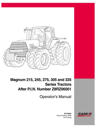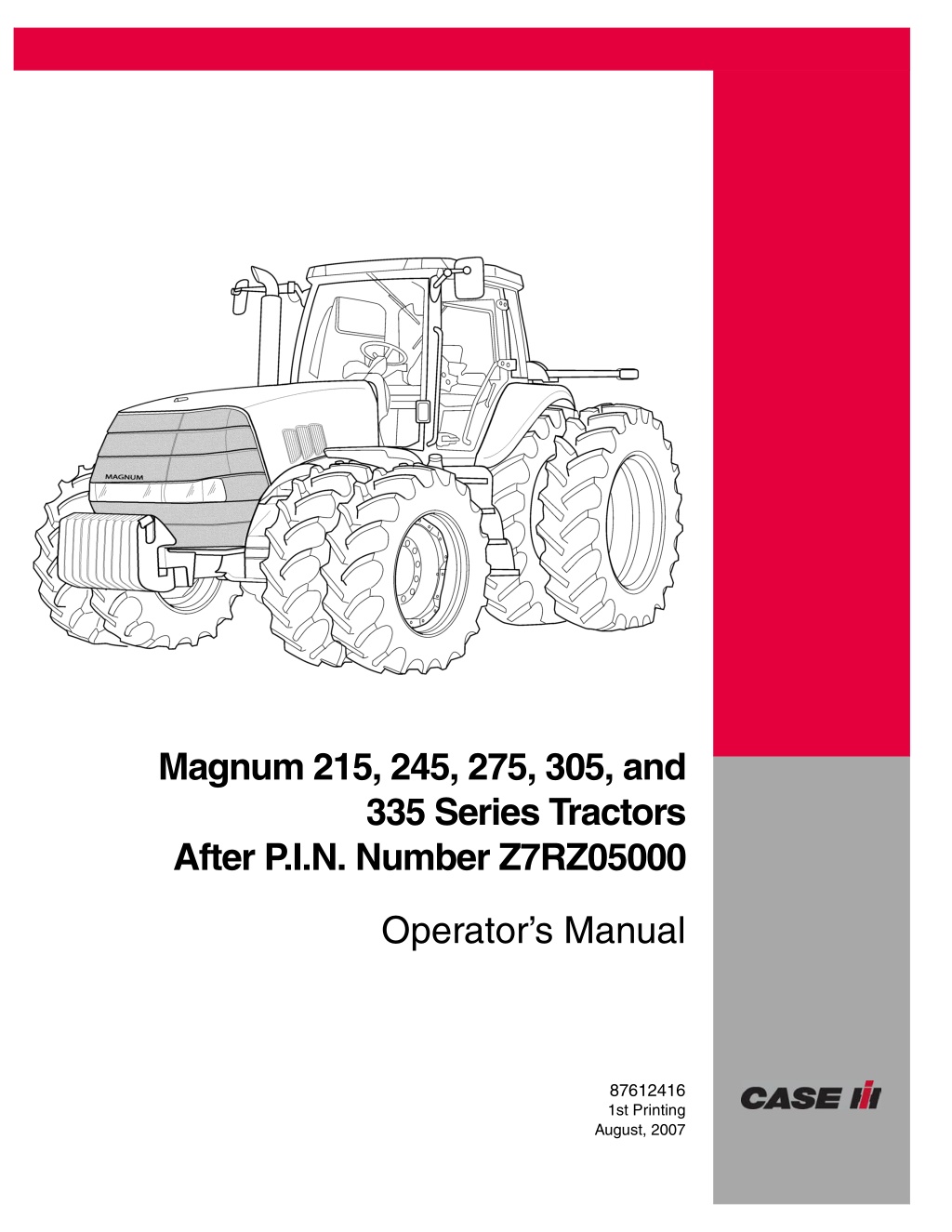
Case IH Magnum 215 245 275 305 and 335 Series Tractors (After Pin NumberZ7RZ05000) Operator’s Manual Instant Download (Publication No.87612416)
Please open the website below to get the complete manualnn//
Download Presentation

Please find below an Image/Link to download the presentation.
The content on the website is provided AS IS for your information and personal use only. It may not be sold, licensed, or shared on other websites without obtaining consent from the author. Download presentation by click this link. If you encounter any issues during the download, it is possible that the publisher has removed the file from their server.
E N D
Presentation Transcript
Magnum 215, 245, 275, 305, and 335 Series Tractors After P.I.N. Number Z7RZ05000 Operator s Manual 87612416 1st Printing August, 2007 CNH America LLC, Racine, WI 53404 U.S.A. Printed in U.S.A.
PERSONAL SAFETY THIS SAFETY ALERT SYMBOL INDICATES IMPORTANT SAFETY MESSAGES IN THIS MANUAL. WHEN YOU SEE THIS SYMBOL, CAREFULLY READ THE MESSAGE THAT FOLLOWS AND BE ALERT TO THE POSSIBILITY OF DEATH OR SERIOUS INJURY. ! M171C Throughout this manual and on the machine s safety decals, you will find precautionary statements: DANGER, WARNING or CAUTION followed by specific instructions or ISO two panel safety pictorial symbols. These precautions are intended for your personal safety. Failure to follow the DANGER, WARNING or CAUTION instructions may result in death or serious bodily injury. DANGER, WARNING or CAUTION are defined as follows: DANGER: Indicates an immediate hazardous situation that, if not avoided, will result in death or serious injury. The color associated with Danger is RED. WARNING: Indicates a potentially hazardous situation that, if not avoided, could result in death or serious injury. The color associated with Warning is ORANGE. CAUTION: Indicates a potentially hazardous situation that, if not avoided, may result in minor or moderate injury. It may also be used to alert against unsafe practices. The color associated with Caution is YELLOW. ISO two panel pictorial symbol decals are defined as follows: The first panel indicates the nature of the hazard. The second panel indicates the appropriate avoidance of the hazard. Background color is YELLOW. Prohibition symbols such as and if used, are RED. STOP WARNING IMPROPER OPERATION OF THIS MACHINE CAN CAUSE DEATH OR SERIOUS INJURY. BEFORE USING THIS MACHINE, MAKE CERTAIN THAT EVERY OPERATOR: ! Is instructed in safe and proper use of the machine. Reads and understands the Manual(s) pertaining to the machine. Reads and understands ALL Safety Decals on the machine. Clears the area of other persons. Learns and practices safe use of machine controls in a safe, clear area before operating this machine on a job site. It is your responsibility to observe pertinent laws and regulations and follow CNH America LLC instructions on machine operation and maintenance.
CNH America LLC Technical Manuals Manuals are available from your Dealer for the operation, service and repair of your machine. For prompt convenient service, contact your Dealer for assistance in obtaining the manuals for your machine. Your Dealer can expedite your order for Operators Manuals, Parts Catalogs, Repair Manuals and maintenance records. Always give the Machine Name, Model and P.I.N. (Product Identification Number) or S.N. (Serial Number) of your machine so your Dealer can provide the correct manuals for your machine. CALIFORNIA Proposition 65 Warning Diesel engine exhaust and some of its constituents are known to the State of California to cause cancer, birth defects, and other reproductive harm. Battery posts, terminals and related accessories contain lead and lead compounds. Wash hands after handling. The company is continually striving to improve its products and therefore reserves the right to make improvements and changes when it becomes practical and possible to do so, without incurring any obligation to make changes or additions to the equipment sold previously. All data given in this manual is subject to production variations. IMPORTANT: OPERATING AND SERVICE MESSAGES DISPLAYED ON THE ELECTRONIC OPERATING PANEL MAY VARY FROM WHAT IS SHOWN IN THE OPERATOR S MANUAL. SHOULD THIS OCCUR ADHERE TO THE LATEST INSTRUCTION ON THE ELECTRONIC OPERATING PANEL. Dimensions and weights are approximate only and the illustrations do not necessarily show the machine in standard condition. For exact information about any particular machine, please consult your dealer.
https://www.ebooklibonline.com Hello dear friend! Thank you very much for reading. Enter the link into your browser. The full manual is available for immediate download. https://www.ebooklibonline.com
GENERAL TABLE OF CONTENTS 1 TO THE OWNER . . . . . . . . . . . . . . . . . . . . . . . . . . . . . . . . . . . . . . . . . . . . . . . . . . . . . . . . . . . . . . . . . . . . . . 1 STATEMENT OF TRACTOR INTENDED USE . . . . . . . . . . . . . . . . . . . . . . . . . . . . . . . . . . . . . . . . . . . . . . . . 1 OPERATOR S MANUAL STORAGE COMPARTMENT . . . . . . . . . . . . . . . . . . . . . . . . . . . . . . . . . . . . . . . . . 1 TRANSPORT TOWED EQUIPMENT AT SAFE SPEEDS . . . . . . . . . . . . . . . . . . . . . . . . . . . . . . . . . . . . . . . 2 PRODUCT IDENTIFICATION AND SERIAL NUMBERS . . . . . . . . . . . . . . . . . . . . . . . . . . . . . . . . . . . . . . . . 4 MACHINE COMPONENTS . . . . . . . . . . . . . . . . . . . . . . . . . . . . . . . . . . . . . . . . . . . . . . . . . . . . . . . . . . . . . . . . 6 BUSINESS BAND RADIOS . . . . . . . . . . . . . . . . . . . . . . . . . . . . . . . . . . . . . . . . . . . . . . . . . . . . . . . . . . . . . . . 8 FRAME REINFORCEMENT KITS . . . . . . . . . . . . . . . . . . . . . . . . . . . . . . . . . . . . . . . . . . . . . . . . . . . . . . . . . . 9 2 SAFETY/DECALS . . . . . . . . . . . . . . . . . . . . . . . . . . . . . . . . . . . . . . . . . . . . . . . . . . . . . . . . . . . . . . . . . . . . 10 SAFETY RULES . . . . . . . . . . . . . . . . . . . . . . . . . . . . . . . . . . . . . . . . . . . . . . . . . . . . . . . . . . . . . . . . . . . . . . . 10 PERSONAL SAFETY . . . . . . . . . . . . . . . . . . . . . . . . . . . . . . . . . . . . . . . . . . . . . . . . . . . . . . . . . . . . . . . . . . . 13 INSTRUCTIONAL SEAT SAFETY . . . . . . . . . . . . . . . . . . . . . . . . . . . . . . . . . . . . . . . . . . . . . . . . . . . . . . . . . 13 MAINTENANCE SAFETY . . . . . . . . . . . . . . . . . . . . . . . . . . . . . . . . . . . . . . . . . . . . . . . . . . . . . . . . . . . . . . . . 14 FIRE SAFETY . . . . . . . . . . . . . . . . . . . . . . . . . . . . . . . . . . . . . . . . . . . . . . . . . . . . . . . . . . . . . . . . . . . . . . . . . 14 BATTERY SAFETY . . . . . . . . . . . . . . . . . . . . . . . . . . . . . . . . . . . . . . . . . . . . . . . . . . . . . . . . . . . . . . . . . . . . . 14 MACHINE OPERATION AND ROLL-OVER SAFETY . . . . . . . . . . . . . . . . . . . . . . . . . . . . . . . . . . . . . . . . . 15 HAZARDOUS CHEMICALS . . . . . . . . . . . . . . . . . . . . . . . . . . . . . . . . . . . . . . . . . . . . . . . . . . . . . . . . . . . . . . 15 SAFETY DECALS . . . . . . . . . . . . . . . . . . . . . . . . . . . . . . . . . . . . . . . . . . . . . . . . . . . . . . . . . . . . . . . . . . . . . . 16 ROLLOVER PROTECTIVE STRUCTURE (ROPS) . . . . . . . . . . . . . . . . . . . . . . . . . . . . . . . . . . . . . . . . . . . 22 CAB STRUCTURAL FRAME (CSF) . . . . . . . . . . . . . . . . . . . . . . . . . . . . . . . . . . . . . . . . . . . . . . . . . . . . . . . . 22 CLEANING CAB WINDOWS . . . . . . . . . . . . . . . . . . . . . . . . . . . . . . . . . . . . . . . . . . . . . . . . . . . . . . . . . . . . . 23 INTERIOR REAR VIEW MIRROR . . . . . . . . . . . . . . . . . . . . . . . . . . . . . . . . . . . . . . . . . . . . . . . . . . . . . . . . . 23 SEAT BELTS . . . . . . . . . . . . . . . . . . . . . . . . . . . . . . . . . . . . . . . . . . . . . . . . . . . . . . . . . . . . . . . . . . . . . . . . . . 24 TRACTOR WARNING LAMPS AND SLOW MOVING VEHICLE (SMV) SYMBOL . . . . . . . . . . . . . . . . . . . 25 IMPLEMENT WARNING LAMPS AND SMV SYMBOL . . . . . . . . . . . . . . . . . . . . . . . . . . . . . . . . . . . . . . . . . 28 SAFETY CHAIN . . . . . . . . . . . . . . . . . . . . . . . . . . . . . . . . . . . . . . . . . . . . . . . . . . . . . . . . . . . . . . . . . . . . . . . 29 3 OPERATING CONTROLS . . . . . . . . . . . . . . . . . . . . . . . . . . . . . . . . . . . . . . . . . . . . . . . . . . . . . . . . . . . . . . 30 TRACTOR ACCESS . . . . . . . . . . . . . . . . . . . . . . . . . . . . . . . . . . . . . . . . . . . . . . . . . . . . . . . . . . . . . . . . . . . . 30 OPERATOR SEAT AND CONTROLS . . . . . . . . . . . . . . . . . . . . . . . . . . . . . . . . . . . . . . . . . . . . . . . . . . . . . . 31 INSTRUCTIONAL SEAT (IF EQUIPPED) . . . . . . . . . . . . . . . . . . . . . . . . . . . . . . . . . . . . . . . . . . . . . . . . . . . 34 STEERING COLUMN CONTROLS . . . . . . . . . . . . . . . . . . . . . . . . . . . . . . . . . . . . . . . . . . . . . . . . . . . . . . . . 35 CENTER CONSOLE CONTROLS . . . . . . . . . . . . . . . . . . . . . . . . . . . . . . . . . . . . . . . . . . . . . . . . . . . . . . . . . 37 FOOT PEDALS . . . . . . . . . . . . . . . . . . . . . . . . . . . . . . . . . . . . . . . . . . . . . . . . . . . . . . . . . . . . . . . . . . . . . . . . 39 RIGHT HAND CONSOLE CONTROLS . . . . . . . . . . . . . . . . . . . . . . . . . . . . . . . . . . . . . . . . . . . . . . . . . . . . . 40 ARMREST CONSOLE CONTROLS . . . . . . . . . . . . . . . . . . . . . . . . . . . . . . . . . . . . . . . . . . . . . . . . . . . . . . . 47 RIGHT HAND FENDER CONTROLS . . . . . . . . . . . . . . . . . . . . . . . . . . . . . . . . . . . . . . . . . . . . . . . . . . . . . . 50 AUTOMATIC TEMPERATURE CONTROL SYSTEM . . . . . . . . . . . . . . . . . . . . . . . . . . . . . . . . . . . . . . . . . . 55 AFS 200 DISPLAY . . . . . . . . . . . . . . . . . . . . . . . . . . . . . . . . . . . . . . . . . . . . . . . . . . . . . . . . . . . . . . . . . . . . . 60 AFS PRO 600 DISPLAY . . . . . . . . . . . . . . . . . . . . . . . . . . . . . . . . . . . . . . . . . . . . . . . . . . . . . . . . . . . . . . . . . 60 REAR WINDOW . . . . . . . . . . . . . . . . . . . . . . . . . . . . . . . . . . . . . . . . . . . . . . . . . . . . . . . . . . . . . . . . . . . . . . . 61 DOME LAMP . . . . . . . . . . . . . . . . . . . . . . . . . . . . . . . . . . . . . . . . . . . . . . . . . . . . . . . . . . . . . . . . . . . . . . . . . . 61 MAP LAMP (IF EQUIPPED) . . . . . . . . . . . . . . . . . . . . . . . . . . . . . . . . . . . . . . . . . . . . . . . . . . . . . . . . . . . . . . 62 STORAGE COMPARTMENT . . . . . . . . . . . . . . . . . . . . . . . . . . . . . . . . . . . . . . . . . . . . . . . . . . . . . . . . . . . . . 62 RADIO (IF EQUIPPED) . . . . . . . . . . . . . . . . . . . . . . . . . . . . . . . . . . . . . . . . . . . . . . . . . . . . . . . . . . . . . . . . . 62 MP3 PLAYER JACK (EARLY VERSION) (IF EQUIPPED) . . . . . . . . . . . . . . . . . . . . . . . . . . . . . . . . . . . . . . 63 MP3 PLAYER JACK (LATER VERSION) (IF EQUIPPED) . . . . . . . . . . . . . . . . . . . . . . . . . . . . . . . . . . . . . . 63 SUN SHADE (IF EQUIPPED) . . . . . . . . . . . . . . . . . . . . . . . . . . . . . . . . . . . . . . . . . . . . . . . . . . . . . . . . . . . . 63 INTERIOR REAR VIEW MIRROR . . . . . . . . . . . . . . . . . . . . . . . . . . . . . . . . . . . . . . . . . . . . . . . . . . . . . . . . . 64 EXTENDABLE MIRRORS (IF EQUIPPED) . . . . . . . . . . . . . . . . . . . . . . . . . . . . . . . . . . . . . . . . . . . . . . . . . . 64 UTILITY CONSOLE . . . . . . . . . . . . . . . . . . . . . . . . . . . . . . . . . . . . . . . . . . . . . . . . . . . . . . . . . . . . . . . . . . . . 64 REAR FENDER CONTROLS . . . . . . . . . . . . . . . . . . . . . . . . . . . . . . . . . . . . . . . . . . . . . . . . . . . . . . . . . . . . . 65 i
4 INSTRUMENTATION . . . . . . . . . . . . . . . . . . . . . . . . . . . . . . . . . . . . . . . . . . . . . . . . . . . . . . . . . . . . . . . . . 66 INSTRUMENTATION CLUSTER OVERVIEW . . . . . . . . . . . . . . . . . . . . . . . . . . . . . . . . . . . . . . . . . . . . . . . . 66 PROGRAMMING THE INSTRUMENTATION DISPLAY . . . . . . . . . . . . . . . . . . . . . . . . . . . . . . . . . . . . . . . . 73 PROGRAMMING THE OPERATOR ADJUST MENU . . . . . . . . . . . . . . . . . . . . . . . . . . . . . . . . . . . . . . . . . . 79 WARNING/FAULT DISPLAYS . . . . . . . . . . . . . . . . . . . . . . . . . . . . . . . . . . . . . . . . . . . . . . . . . . . . . . . . . . . . 82 INSTRUMENTATION CLUSTER OPERATION . . . . . . . . . . . . . . . . . . . . . . . . . . . . . . . . . . . . . . . . . . . . . . . 88 5 OPERATING INSTRUCTIONS . . . . . . . . . . . . . . . . . . . . . . . . . . . . . . . . . . . . . . . . . . . . . . . . . . . . . . . . . 107 BEFORE STARTING THE ENGINE . . . . . . . . . . . . . . . . . . . . . . . . . . . . . . . . . . . . . . . . . . . . . . . . . . . . . . . 107 SERVICE INDICATOR LAMPS AND DISPLAYS . . . . . . . . . . . . . . . . . . . . . . . . . . . . . . . . . . . . . . . . . . . . . 108 SEAT BELTS . . . . . . . . . . . . . . . . . . . . . . . . . . . . . . . . . . . . . . . . . . . . . . . . . . . . . . . . . . . . . . . . . . . . . . . . . 109 STARTING THE ENGINE . . . . . . . . . . . . . . . . . . . . . . . . . . . . . . . . . . . . . . . . . . . . . . . . . . . . . . . . . . . . . . . 110 STOPPING THE ENGINE . . . . . . . . . . . . . . . . . . . . . . . . . . . . . . . . . . . . . . . . . . . . . . . . . . . . . . . . . . . . . . . 112 COLD TEMPERATURE OPERATION . . . . . . . . . . . . . . . . . . . . . . . . . . . . . . . . . . . . . . . . . . . . . . . . . . . . . 113 POWER SHIFT TRANSMISSION . . . . . . . . . . . . . . . . . . . . . . . . . . . . . . . . . . . . . . . . . . . . . . . . . . . . . . . . . 116 TRANSMISSION . . . . . . . . . . . . . . . . . . . . . . . . . . . . . . . . . . . . . . . . . . . . . . . . . . . . . . . . . . . . . . . . . . . . . . 117 SUSPENDED MFD AXLE OPERATION (IF EQUIPPED) . . . . . . . . . . . . . . . . . . . . . . . . . . . . . . . . . . . . . . 135 CUSHION HITCH RIDE CONTROL OPERATION (IF EQUIPPED) . . . . . . . . . . . . . . . . . . . . . . . . . . . . . . 142 CONSTANT ENGINE SPEED OPERATION . . . . . . . . . . . . . . . . . . . . . . . . . . . . . . . . . . . . . . . . . . . . . . . . 144 TOWING THE TRACTOR . . . . . . . . . . . . . . . . . . . . . . . . . . . . . . . . . . . . . . . . . . . . . . . . . . . . . . . . . . . . . . . 145 HOW TO TRANSPORT THE TRACTOR . . . . . . . . . . . . . . . . . . . . . . . . . . . . . . . . . . . . . . . . . . . . . . . . . . . 148 6 FIELD OPERATION . . . . . . . . . . . . . . . . . . . . . . . . . . . . . . . . . . . . . . . . . . . . . . . . . . . . . . . . . . . . . . . . . 149 GENERAL PROCEDURES FOR CONNECTING IMPLEMENTS . . . . . . . . . . . . . . . . . . . . . . . . . . . . . . . . 149 POWER TAKEOFF (PTO) . . . . . . . . . . . . . . . . . . . . . . . . . . . . . . . . . . . . . . . . . . . . . . . . . . . . . . . . . . . . . . . 151 THREE POINT HITCH . . . . . . . . . . . . . . . . . . . . . . . . . . . . . . . . . . . . . . . . . . . . . . . . . . . . . . . . . . . . . . . . . . 166 HITCH OPERATION . . . . . . . . . . . . . . . . . . . . . . . . . . . . . . . . . . . . . . . . . . . . . . . . . . . . . . . . . . . . . . . . . . . 187 DRAWBAR PREPARATION . . . . . . . . . . . . . . . . . . . . . . . . . . . . . . . . . . . . . . . . . . . . . . . . . . . . . . . . . . . . . 205 REMOTE HYDRAULICS . . . . . . . . . . . . . . . . . . . . . . . . . . . . . . . . . . . . . . . . . . . . . . . . . . . . . . . . . . . . . . . . 213 LOADER OPERATION . . . . . . . . . . . . . . . . . . . . . . . . . . . . . . . . . . . . . . . . . . . . . . . . . . . . . . . . . . . . . . . . . 230 CHEMICAL TANK MOUNTING . . . . . . . . . . . . . . . . . . . . . . . . . . . . . . . . . . . . . . . . . . . . . . . . . . . . . . . . . . . 231 AUXILIARY POWER CONNECTIONS . . . . . . . . . . . . . . . . . . . . . . . . . . . . . . . . . . . . . . . . . . . . . . . . . . . . . 233 MONITOR MOUNTING . . . . . . . . . . . . . . . . . . . . . . . . . . . . . . . . . . . . . . . . . . . . . . . . . . . . . . . . . . . . . . . . . 236 GROUND SPEED SENSOR CONNECTOR . . . . . . . . . . . . . . . . . . . . . . . . . . . . . . . . . . . . . . . . . . . . . . . . . 237 TRAILER BRAKE CONNECTOR (IF EQUIPPED) . . . . . . . . . . . . . . . . . . . . . . . . . . . . . . . . . . . . . . . . . . . . 238 CAB STEPS . . . . . . . . . . . . . . . . . . . . . . . . . . . . . . . . . . . . . . . . . . . . . . . . . . . . . . . . . . . . . . . . . . . . . . . . . . 240 7 IN-FIELD PERFORMANCE . . . . . . . . . . . . . . . . . . . . . . . . . . . . . . . . . . . . . . . . . . . . . . . . . . . . . . . . . . . 241 DIFFERENTIAL LOCK . . . . . . . . . . . . . . . . . . . . . . . . . . . . . . . . . . . . . . . . . . . . . . . . . . . . . . . . . . . . . . . . . . 241 MFD OPERATION . . . . . . . . . . . . . . . . . . . . . . . . . . . . . . . . . . . . . . . . . . . . . . . . . . . . . . . . . . . . . . . . . . . . . 244 BALLASTING YOUR TRACTOR FOR OPTIMUM PERFORMANCE . . . . . . . . . . . . . . . . . . . . . . . . . . . . . 249 WHEEL SLIP . . . . . . . . . . . . . . . . . . . . . . . . . . . . . . . . . . . . . . . . . . . . . . . . . . . . . . . . . . . . . . . . . . . . . . . . . 273 POWER HOP . . . . . . . . . . . . . . . . . . . . . . . . . . . . . . . . . . . . . . . . . . . . . . . . . . . . . . . . . . . . . . . . . . . . . . . . . 275 MECHANICAL FRONT DRIVE (MFD) AXLES . . . . . . . . . . . . . . . . . . . . . . . . . . . . . . . . . . . . . . . . . . . . . . . 276 MFD STEERING AND OSCILLATION STOPS . . . . . . . . . . . . . . . . . . . . . . . . . . . . . . . . . . . . . . . . . . . . . . 283 FRONT WHEEL FENDERS (IF EQUIPPED) . . . . . . . . . . . . . . . . . . . . . . . . . . . . . . . . . . . . . . . . . . . . . . . . 291 REAR AXLE . . . . . . . . . . . . . . . . . . . . . . . . . . . . . . . . . . . . . . . . . . . . . . . . . . . . . . . . . . . . . . . . . . . . . . . . . . 295 TRACTOR JACKING POINTS . . . . . . . . . . . . . . . . . . . . . . . . . . . . . . . . . . . . . . . . . . . . . . . . . . . . . . . . . . . 298 REAR WHEEL TREAD SETTING - SINGLES . . . . . . . . . . . . . . . . . . . . . . . . . . . . . . . . . . . . . . . . . . . . . . . 300 REAR WHEEL TREAD SETTING - DUALS . . . . . . . . . . . . . . . . . . . . . . . . . . . . . . . . . . . . . . . . . . . . . . . . . 302 REAR WHEEL TREAD SETTING - TRIPLES . . . . . . . . . . . . . . . . . . . . . . . . . . . . . . . . . . . . . . . . . . . . . . . 311 ii
8 LUBRICATION/FILTERS/FLUIDS/MAINTENANCE . . . . . . . . . . . . . . . . . . . . . . . . . . . . . . . . . . . . . . . . 314 ENVIRONMENT . . . . . . . . . . . . . . . . . . . . . . . . . . . . . . . . . . . . . . . . . . . . . . . . . . . . . . . . . . . . . . . . . . . . . . 314 PLASTIC AND RESIN PARTS . . . . . . . . . . . . . . . . . . . . . . . . . . . . . . . . . . . . . . . . . . . . . . . . . . . . . . . . . . . 314 TOOL BOX (IF EQUIPPED) . . . . . . . . . . . . . . . . . . . . . . . . . . . . . . . . . . . . . . . . . . . . . . . . . . . . . . . . . . . . . 314 SYSTEM CAPACITIES . . . . . . . . . . . . . . . . . . . . . . . . . . . . . . . . . . . . . . . . . . . . . . . . . . . . . . . . . . . . . . . . . 315 OPENING THE HOOD . . . . . . . . . . . . . . . . . . . . . . . . . . . . . . . . . . . . . . . . . . . . . . . . . . . . . . . . . . . . . . . . . 319 LUBRICATION/MAINTENANCE CHART . . . . . . . . . . . . . . . . . . . . . . . . . . . . . . . . . . . . . . . . . . . . . . . . . . 321 9 ELECTRICAL SYSTEM . . . . . . . . . . . . . . . . . . . . . . . . . . . . . . . . . . . . . . . . . . . . . . . . . . . . . . . . . . . . . . . 371 SPECIFICATIONS . . . . . . . . . . . . . . . . . . . . . . . . . . . . . . . . . . . . . . . . . . . . . . . . . . . . . . . . . . . . . . . . . . . . 371 RADIO REGIONAL PROGRAMMING . . . . . . . . . . . . . . . . . . . . . . . . . . . . . . . . . . . . . . . . . . . . . . . . . . . . . 376 BATTERY SYSTEM SERVICING . . . . . . . . . . . . . . . . . . . . . . . . . . . . . . . . . . . . . . . . . . . . . . . . . . . . . . . . 377 BULB AND LAMP REPLACEMENT . . . . . . . . . . . . . . . . . . . . . . . . . . . . . . . . . . . . . . . . . . . . . . . . . . . . . . . 380 10 SPECIFICATIONS . . . . . . . . . . . . . . . . . . . . . . . . . . . . . . . . . . . . . . . . . . . . . . . . . . . . . . . . . . . . . . . . . . 396 DIESEL ENGINE . . . . . . . . . . . . . . . . . . . . . . . . . . . . . . . . . . . . . . . . . . . . . . . . . . . . . . . . . . . . . . . . . . . . . . 396 POWER TRAIN . . . . . . . . . . . . . . . . . . . . . . . . . . . . . . . . . . . . . . . . . . . . . . . . . . . . . . . . . . . . . . . . . . . . . . . 397 TRAVEL SPEEDS . . . . . . . . . . . . . . . . . . . . . . . . . . . . . . . . . . . . . . . . . . . . . . . . . . . . . . . . . . . . . . . . . . . . . 401 MAXIMUM RECOMMENDED OPERATING WEIGHTS . . . . . . . . . . . . . . . . . . . . . . . . . . . . . . . . . . . . . . . 412 INDEX . . . . . . . . . . . . . . . . . . . . . . . . . . . . . . . . . . . . . . . . . . . . . . . . . . . . . . . . . . . . . . . . . . . . . . . . . . . . . . . . 415 iii
Template Name: OML_2_col Template Date: 1994_04_22 6-31480 1 TO THE OWNER TO THE OWNER This manual contains important information about the safe operation, adjustment and routine maintenance of your Case IH Magnum Series Tractor. The manual is divided into ten sections as outlined in the General Table of Contents Page(s). Refer to the Detail Index at the end of this manual for locating specific items about your tractor. This Operator s Manual should be stored in the manual compartment on this machine. Make sure this manual is in good condition. Contact your Case IH dealer to obtain additional manuals. Contact your dealer for any further information or assistance about your machine. Your dealer has Case IH approved service parts. Your dealer has technicians with special training that know the best methods of repair and maintenance for your tractor. DO NOT operate or permit anyone to operate or service this machine until you or the other persons have read this manual. Use only trained operators who have demonstrated the ability to operate and service this machine correctly and safely. STATEMENT OF TRACTOR INTENDED USE The Case IH Magnum Series Tractor, with standard equipment and authorized attachments, is intended to be used for customary farming, land leveling and related agriculture operations. Installation of utility (dozer) blades, tile plows, or push bars on the tractor is not recommended. Any tractor damage resulting from the installation and/or use of such equipment is not covered by the tractor warranty. Consult an authorized dealer or Case IH on changes, additions or modifications that may be required for this machine to comply with various regulations and safety requirements. Unauthorized modifications will cause serious injury or death. Anyone making such unauthorized modifications is responsible for the consequences. OPERATOR S MANUAL STORAGE COMPARTMENT MK99H025 NOTE: The right hand and left hand side of the tractor used in this manual are the same as your right hand and left hand when sitting in the tractor seat looking forward. Keep the Operator s Manual in the storage compartment provided on your tractor. The Operator s Manual must be available for use by all operators. 1
1 TO THE OWNER TRANSPORT TOWED EQUIPMENT AT SAFE SPEEDS Your tractor is capable of operating at speeds that exceed the maximum allowable transport speed for most towed equipment. Before transporting towed equipment, read the operator manual for the equipment. Ensure that equipment is correctly installed, know how to transport it safely, Never transport at speeds that exceed the equipment's maximum transport speed. Exceeding the equipment's maximum transport speed may result in reduced braking performance and/or loss of control of the tractor and its towed equipment. Unless otherwise specified by the equipment manufacturer or legislation, observe the following when towing. For towed equipment without brakes. Do not tow equipment that does not have brakes At speeds over 32 km/h (20 mile/h); or That, when fully loaded, has a mass (weight) over 1.5 metric tons (3300 lb) and more than 1.5 times the mass (weight) of the tractor When trailer brakes are required by law That has a mass (weight) that exceeds the values declared on the tractor PIN plate (as applicable) For towed equipment with brakes. Do not tow equipment that has brakes At speeds over 40 km/h (25 mile/h); or That, when fully loaded has a mass (weight) more than 2.5 times the mass (weight) of the tractor That has a mass (weight) that exceeds the values declared on the tractor PIN plate (as applicable) 2
1 TO THE OWNER MAGNUM SERIES TRACTOR RH02H168 Magnum Tractor RH02H170 Magnum Tractor with Front and Rear Duals 3
1 TO THE OWNER PRODUCT IDENTIFICATION AND SERIAL NUMBERS Write your tractor Model Number, Product Identification Number (P.I.N.) and Serial Numbers of major components on the lines provided. If needed, give these numbers to your Case IH dealer when you need parts or information for your machine. TRACTOR MODEL AND PRODUCT IDENTIFICATION NUMBER Model:___________________________________ P.I.N. *: __________________________________ Located on right hand front frame casting. RH02H283 ROLL OVER PROTECTION SYSTEM (ROPS) SERIAL NUMBER ________________________________________ Located on the right hand cab floor. RH02H174 ENGINE SERIAL NUMBER ________________________________________ Located on front left hand side of engine. RD05J163 4
1 TO THE OWNER TRANSMISSION SERIAL NUMBER ________________________________________ Located on the right hand side of the transmission behind the fuel tank and to the left of the ground stud. RH02H176 AXLE SERIAL NUMBER ________________________________________ MFD AXLE: Located on the rear right hand side of the axle housing. SUSPENDED AXLE: Located on the front right hand side of the axle housing. RH02H178 MFD Axle RH02G351 Suspended Axle 5
1 TO THE OWNER MACHINE COMPONENTS 9 10 10 9 1 7 9 13 2 5 4 12 11 11 10 8 3 10 6 RH02H170 1. ROPS CAB 2. HAND RAIL 3. STEPS 4. FUEL TANK 5. HOOD 6. FRONT WEIGHTS 7. EXHAUST STACK 8. WIDE TRANSPORT MARKER 9. AMBER WARNING LAMP 10. WORK LAMPS 11. ROAD/WORK LAMPS 12. HID LAMP 13. AMBER REFLECTOR 6
1 TO THE OWNER 1 12 6 2 6 2 10 11 12 9 8 6 3 7 4 5 RH02H171 1. ROPS CAB 2. REAR VIEW MIRROR 3. REAR HITCH 4. POWER TAKEOFF (PTO) 5. DRAWBAR 6. AMBER WARNING LAMPS 7. TAIL AND BRAKE LAMP 8. SMV SYMBOL 9. WIDE TRANSPORT MARKER 10. RED REFLECTOR 11. ORANGE REFLECTOR 12. ROOF AND FENDER WORK LAMPS/HID LAMPS 7
1 TO THE OWNER BUSINESS BAND RADIOS The power supply harness and antenna cable with low profile mount for a business band radio are installed in tractors equipped with the business radio ready option. The business band radio, radio mounting bracket, and antenna are owner supplied. The recommended mounting location for the business band radio is under and to the right of the AM/FM radio. The bracket supplied with the business band radio must be used. The AM/FM radio must be removed for access to the power and antenna harnesses and for proper positioning of the bracket. Mount the business radio bracket to the AM/FM radio-mounting bracket (hidden by the headliner). Attach the microphone to the same bracket or the business band radio. NOTE: When drilling mounting holes, do not damage any wiring harnesses. Use blunt tip screws of an appropriate length to install the bracket and avoid contact with the AM/FM radio or harnesses. RH02H164 Route the power and antenna harnesses to the business band radio. Drill a hole through the headliner at this location, and use a grommet to protect the wires and cover the hole. The antenna mast mounting stud (1) is located on the cab roof near the operator s door. Remove the protective cap and install the antenna on the threaded stud. The stud is already wired with RF-58/U cable, which is routed behind the AM/FM radio for easy connection to your business band radio. RG02H173 NOTE: The antenna mast must be purchased locally and must be compatible with an Antenna Specialist Model K-794 low profile antenna mount. See Antenna Specialists at additional information. 1 www.antenna.com for 2 3 4 NOTE: See your Case IH dealer for additional information and procedures for installing a business band radio if your tractor is not business band radio ready. 5 6 RI02H010 1. PROTECTIVE CAP 2. MOUNTING STUD 3. O-RING 4. CAB ROOF 5. THREADED FASTENER 6. CABLE 8
1 TO THE OWNER FRAME REINFORCEMENT KITS Scraper Front Frame Side Plate Kit #87648802 A scraper front frame side plate kit is available for all Magnum tractors. This kit is designed to help strengthen the surround frame and mounting anytime the tractor is involved in operations where a lot of twisting action or front oscillation, takes place between front and rear axles. This type of action is observed especially in scraper operations. Frame Support Kit #87647844 A frame support kit is available for all Magnum tractors. This kit is intended for field applications which put very high fore/aft bending loads into the tractor chassis such as extremely heavy fully mounted rear implement and high front end weight. 9
Template Name: OML_2_col Template Date: 1994_04_22 6-31480 2 SAFETY/DECALS This section gives important safety information for your tractor. SAFETY Understand that your safety and the safety of other persons is measured by how you service and operate this machine. Know the positions and operation of all controls before you try to operate. MAKE SURE YOU CHECK ALL CONTROLS IN A SAFE AREA BEFORE STARTING YOUR WORK. The safety information given in this manual does not replace safety codes, insurance needs, federal, state and local laws. Make sure your machine has the correct equipment needed by the local laws and regulations. We are continuing to work for your safety by making tractors with better protection and by providing these rules for safe operation. READ THIS MANUAL COMPLETELY and make sure you understand the controls. All equipment has limits. Make sure you understand the speed, brakes, steering stability and load characteristics of this machine before you start to operate. WARNING: THIS SAFETY ALERT SYMBOL INDICATES IMPORTANT SAFETY MESSAGES IN THIS MANUAL. WHEN YOU SEE THIS SYMBOL, CAREFULLY READ THE MESSAGE THAT FOLLOWS AND BE ALERT TO THE POSSIBILITY OF PERSONAL INJURY OR DEATH. ! SM171B ! ! SAFETY RULES Before starting the engine, be sure all operating controls are in neutral or park lock position. This will eliminate accidental movement of the machine or start up of power driven equipment. Before leaving the tractor, stop the engine, put all controls in neutral or park lock position, remove the key from the key switch. R301B Stay off slopes too steep for safe operation. Shift down before you start up or down a hill with a heavy load. Avoid free wheeling . R106E Operate controls only when seated in the operator s seat. R123A R137A Do not drive on roads, or at high speed anywhere, with the differential lock engaged. Difficult steering will occur and can result in an accident. In field operation, use the differential lock for traction improvement, but release for turning at row ends. Securely fasten your seat belt. Your machine is equipped with a ROPS cab for your protection. The seat belt can help insure your safety if it is used and maintained. Never wear a seat belt loosely or with slack in the belt system. Never wear the belt in a twisted condition or pinched between the seat structural members. Inspect seat belt webbing, buckle and retractors to ensure they are not damaged. If damage is apparent, repair before operating the tractor. M437A R116A Do not exceed implement transport speed or the speed rating on the implement tires. Review the implements Operator s Manual for specifications. M1219 A frequent cause of death or serious injury is persons falling off machinery and being run over. Keep cab door closed. Instructional seat is used only for instructing or service diagnosing only. DO NOT permit others to ride, especially children. Seat belt (if equipped) must be worn at all times. M488C 10
2 SAFETY/DECALS ! ! SAFETY RULES Travel speed should be such that complete control and machine stability is maintained at all times. Where possible, avoid operating near ditches, embankments and holes. Reduce speed when turning, crossing slopes, and on rough, slick or muddy surfaces. When dismounting from the tractor with the PTO running, keep clear of all moving parts as they are a potential safety hazard. doing stationary PTO work and R127A Never operate the engine in a closed building. Proper ventilation is circumstances. R109B required under all Collision of high speed road traffic and slow moving machines can cause personal injury or death. On roads, use flasher lights according to local laws. Keep SMV emblem visible. Pull over to let faster traffic pass. Slow down and signal before turning off. R142A Never refuel the machine when the engine is hot or running. Never smoke while refueling. R139C Check and service cooling system according to the maintenance instructions. Hot coolant can spray out if the deaeration tank cap is removed while system is hot. To remove the deaeration tank cap, let system cool, turn to first notch, then wait until all pressure is released. Scalding can result from fast removal of the cap. R110E Brake pedals must be locked together for road travel. This will insure uniform brake application and maximum stopping ability. R112A For speeds up to 16 km/h (10 MPH), make sure that the weight of a trailed vehicle that is not equipped with brakes does NOT EXCEED 1.5 times the tractor weight. For speeds up to 40 km/h (25 MPH), make sure that the weight of a trailed vehicle that is not equipped with brakes, does NOT EXCEED the weight of the tractor. Stopping distance increases with increasing speed as the weight of the towed load increases, especially on hills and slopes. R141C Hydraulic oil or diesel fuel leaking under pressure can penetrate the skin and cause infection or other injury. To Prevent Personal Injury: Relieve all pressure before disconnecting fluid lines. Before applying pressure, make sure all connections are tight and components are in good condition. Never use your hand to check for suspected leaks under pressure. Use a piece of cardboard or wood for this purpose. If injured by leaking fluid, see your doctor immediately. M814A Extra weight and bad traction conditions such as mud or ice increase your stopping distance. Remember that liquid in the tires, weights on the machine or wheels, tanks filled with fertilizer, herbicides or insecticides - all these add weight and increase the distance you need in which to stop. R149B Rear upset can result if pulling from wrong location on tractor. Hitch only to the drawbar. Use three point hitch only with the implements designed for its use - not as a drawbar. R138B PTO driven machinery can cause serious injury. Before working on or near the PTO shaft, or servicing or clearing the driven machine, put the PTO lever in the DISENGAGE position and STOP the engine. R119A Battery explosion and/or damage to electrical components can result from improper connection of booster batteries or charger. Connect positive to positive and negative to negative. Externally, battery acid can cause burns and blindness, and taken internally it is poisonous. R154A Whenever a PTO driven machine is in operation, the PTO guard must be in place for most operations to prevent injury to the operator or bystanders. Where attachments, such as pumps, are installed on the PTO shaft (especially if the tractor PTO guard is moved upward or removed), extended shielding equivalent to the PTO guard must be installed with the attachment. Install the PTO guard to its original position immediately when the attachment is removed. R146B It is good practice to carry a fire extinguisher on the machine. Be sure that the extinguisher is properly maintained and be familiar with its proper use. R102B R273A 11
Suggest: If the above button click is invalid. Please download this document first, and then click the above link to download the complete manual. Thank you so much for reading
2 SAFETY/DECALS ! ! SAFETY RULES Do not look directly into the front or rear High Intensity Discharge Lamps. Eye damage can occur. Always start the engine from the operator s seat. Never attempt to bypass start, the tractor may suddenly start and move resulting in serious or fatal injury. M638 M787 If the tractor stalls, hydraulic pressure drops, and the brake pedals can be pushed to the floor. Activating BOTH pedals will engage the park brake. This tractor is equipped with a spring applied mechanical front wheel drive (MFD) clutch and a front axle limited slip differential. Even with the MFD engaging switch in the OFF position, the front axle clutch can propel both front wheels if any of the following conditions occur: M768 Clean tractor of field trash daily or more frequently depending upon conditions. Trash accumulation on the tractor can cause damage and fire. 1. The engine is turned off. 2. The engine is stopped when the rear wheels are still coasting. 3. Any interruption in the clutch operating hydraulic system flow or pressure or in the electrical controls for clutch operation. 4. Both brakes are applied. M791 Always keep the cab windows and rear view mirrors clean to provide the best all around visibility while operating the tractor. R416 Do not pull with elastic tow ropes. Elastic tow rope stores energy. Sudden release may cause injury or death. For these reasons, the following service procedures must be followed. M425 Before rotating the rear wheels of a MFD tractor (if you are using engine power with the rear wheels supported off the ground), one of the following procedures must be done to prevent an accidental tractor movement. Young children should not be permitted to operate or ride the circumstances. tractor under any M630 Do not tamper with the ballast on the front or rear High Intensity Discharge Lamps as it contains high voltage. Personal injury or death can occur. M639 1. Jack up and support BOTH front wheels completely off the ground. OR ALWAYS make sure working area is clear of other persons, pets, tools, etc. before you start operating this machine. NEVER allow anybody in work area during machine operation. 2. Disconnect the front wheel drive shaft. Doing one of these two procedures will insure that engagement of the MFD clutch will not result in tractor movement. R292B ALWAYS sound horn before starting the machine. M835 To avoid possible eye damage from microwave signals emitted by the radar sensor, do not look directly into the sensor face. M788 To prevent tractor movement, always apply the park brake whenever the tractor is parked with the engine running. The park brake is applied automatically when the engine is shut down. M627 12
https://www.ebooklibonline.com Hello dear friend! Thank you very much for reading. Enter the link into your browser. The full manual is available for immediate download. https://www.ebooklibonline.com

