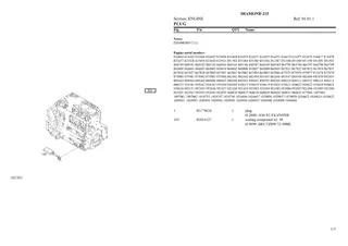
Caterpillar Cat 215 EXCAVATOR (Prefix 14Z) Service Repair Manual Instant Download (14Z00649 and up)
Please open the website below to get the complete manualnn//

Download Presentation

Please find below an Image/Link to download the presentation.
The content on the website is provided AS IS for your information and personal use only. It may not be sold, licensed, or shared on other websites without obtaining consent from the author. Download presentation by click this link. If you encounter any issues during the download, it is possible that the publisher has removed the file from their server.
E N D
Presentation Transcript
215 EXCAVATOR 14Z00649-UP (MACHINE) POWERED BY 3204 ENGINE(SEB... 1/9 Product: EXCAVATOR Model: 215 EXCAVATOR 14Z Configuration: 215 EXCAVATOR 14Z00649-UP (MACHINE) POWERED BY 3204 ENGINE Disassembly and Assembly 3204 VEHICULAR ENGINE FOR 215 EXCAVATOR Media Number -SENR2168-01 Publication Date -01/02/1982 Date Updated -11/10/2001 Fuel Injection Pump Housing And Governor SMCS - 1286-12; 1386-12 Remove Fuel Injection Pump Housing start by: a) remove fuel injection lines b) remove engine hoods 1. Remove turbocharger oil lines (1) from the turbocharger. Remove line (2) from fuel injection pump housing. https://127.0.0.1/sisweb/sisweb/techdoc/techdoc_print_page.jsp?returnurl=/sis... 2021/10/15
215 EXCAVATOR 14Z00649-UP (MACHINE) POWERED BY 3204 ENGINE(SEB... 2/9 2. Disconnect governor control linkage (3) from the governor. 3. Disconnect three fuel lines (4), (5) and (6) from the fuel injection pump. 4. Remove bolts (7) that hold the fuel injection pump housing to the oil manifold for the engine oil cooler. NOTE: When bolt (8) is removed, don't let the spacer on the back side between the fuel block and the alternator bracket fall under the engine. 5. Remove bolt (8) from the alternator bracket and remove the spacer from the back side of the alternator bracket. 6. Remove bolt (9) and plug (10) from the timing gear cover. https://127.0.0.1/sisweb/sisweb/techdoc/techdoc_print_page.jsp?returnurl=/sis... 2021/10/15
215 EXCAVATOR 14Z00649-UP (MACHINE) POWERED BY 3204 ENGINE(SEB... 3/9 7. Loosen bolt (11) in the timing gear a maximum of one turn. 8. Loosen three nuts (12) that hold the pump drive to the timing gear plate until the nuts are even with the end of the studs. 9. Pull the fuel injection pump housing and pump drive away from the timing gear plate until the timing gear is against the front side of the timing gear plate. 10. Install tooling (A) in the timing gear cover to push the pump drive shaft and loosen the timing gear on the shaft as follows: a) Install tooling (A) in the position shown and tighten the locks to hold the tooling in place. NOTICE The tooling must be installed in the position shown so the locks will not damage the water passage in the timing gear cover. https://127.0.0.1/sisweb/sisweb/techdoc/techdoc_print_page.jsp?returnurl=/sis... 2021/10/15
https://www.ebooklibonline.com Hello dear friend! Thank you very much for reading. Enter the link into your browser. The full manual is available for immediate download. https://www.ebooklibonline.com
215 EXCAVATOR 14Z00649-UP (MACHINE) POWERED BY 3204 ENGINE(SEB... 4/9 b) Turn the extension counterclockwise to loosen the bolt in the timing gear. As the bolt is loosened it will push against tooling (A) and push the shaft of the pump drive through the timing gear to loosen the timing gear on the shaft. c) Remove tooling (A) from the timing gear cover. Remove the bolt and washer from the timing gear. 11. Remove the nuts and remove the pump drive, fuel injection pump housing and governor (13) as a unit from the engine. Weight is 50 lb. (23 kg). Install Fuel Injection Pump Housing And Governor 1. Install the bolt and washer in shaft (1) in the pump drive. Remove the plug from the pump drive housing and install tool (A) in the plug hole. Turn shaft (1) until timing pin (A) engages in the notch in the shaft. Tool (A) will hold the fuel injection pump camshaft in the correct position to set the fuel injection timing of the engine. https://127.0.0.1/sisweb/sisweb/techdoc/techdoc_print_page.jsp?returnurl=/sis... 2021/10/15
215 EXCAVATOR 14Z00649-UP (MACHINE) POWERED BY 3204 ENGINE(SEB... 5/9 2. Put the governor, fuel injection pump housing (2) and the pump drive in position on the engine as a unit. Install the nuts that hold the pump drive to the timing gear plate. NOTICE Be extra careful not to damage the O-ring seals when the fuel injection pump housing and governor are installed. 3. Be sure the threads on bolt (3) and the threads in the shaft of the pump drive are not damaged. 4. Install bolt (3) and the washer to hold the timing gear on the shaft. Tighten bolt (3) finger tight only. NOTE: Bolt (3) must be tight enough to hold the gear clearance (backlash) out of the timing gears when the engine is turned but the timing gear must be able to turn on the shaft when the engine is turned to put the No. 1 piston on top center compression position (TDC). 5. Put No. 1 piston at the top center compression position (TDC) with the following procedure: a) Remove plug (4) from the flywheel housing. https://127.0.0.1/sisweb/sisweb/techdoc/techdoc_print_page.jsp?returnurl=/sis... 2021/10/15
215 EXCAVATOR 14Z00649-UP (MACHINE) POWERED BY 3204 ENGINE(SEB... 6/9 b) Turn the crankshaft clockwise (as seen from the front of the engine) until a 3/8"-16 NC bolt (5) at least two inches long can be installed through the timing hole in the flywheel housing and into the hole in the flywheel. NOTE: Never turn the crankshaft backward to install the timing bolt in the flywheel. c) Remove the valve cover. Check to see if both rocker arms for the No. 1 piston can be moved backward and forward by hand. NOTE: The No. 1 piston is at the top center compression position when the bolt is installed in the flywheel and both rocker arms for No. 1 piston can be moved backward and forward. If both rocker arms can not be moved, the No. 1 piston is not at the top center compression position. Remove the bolt from the flywheel. Turn the crankshaft clockwise (as seen from the front of the engine) one full turn (360 ) and install the bolt again. 6. With the timing pin in the fuel injection pump housing and the timing bolt in the flywheel, tighten the bolt in the timing gear to a torque of 111 5 lb.ft. (149 7 N m). 7. Check the timing as follows: a) Remove both the timing pin and timing bolt. b) Turn the crankshaft clockwise (as seen from the front of the engine) two full turns and install the timing pin and bolt again. c) The timing is correct if both the timing pin and timing bolt can be installed at the same time. The timing procedure must be done again if the timing pin and timing bolt can not be installed at the same time. d) Remove the timing pin and timing bolt when the timing is correct. https://127.0.0.1/sisweb/sisweb/techdoc/techdoc_print_page.jsp?returnurl=/sis... 2021/10/15
215 EXCAVATOR 14Z00649-UP (MACHINE) POWERED BY 3204 ENGINE(SEB... 7/9 8. Install the bolts (6) that hold the fuel injection pump housing to the oil manifold for the engine oil cooler. 9. Install plug (7) in the flywheel housing. 10. Install plug (8) in the fuel injection pump housing. 11. Be sure the O-ring seal is in position on plug (11) and put clean oil on the O-ring seal. Put plug (11) in position in the timing gear cover and install the bolt and washer that hold it in place. 12. Put bolt (9) in position in the alternator bracket. Put spacer (10) in position on the back of the alternator bracket and install bolt (9) through spacer (10) and into the fuel block. https://127.0.0.1/sisweb/sisweb/techdoc/techdoc_print_page.jsp?returnurl=/sis... 2021/10/15
215 EXCAVATOR 14Z00649-UP (MACHINE) POWERED BY 3204 ENGINE(SEB... 8/9 13. Connect the fuel lines (12) to the fuel pump drive. 14. Connect the governor linkage (13) to the governor lever. 15. Install turbocharger oil inlet line (14) and oil drain line (15). 16. Install fuel line (16) on bracket. end by: a) install engine hoods b) install fuel injection lines https://127.0.0.1/sisweb/sisweb/techdoc/techdoc_print_page.jsp?returnurl=/sis... 2021/10/15
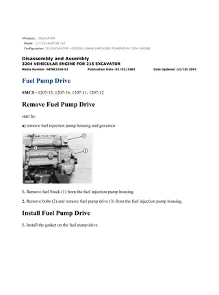
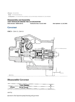
215 EXCAVATOR 14Z00649-UP (MACHINE) POWERED BY 3204 ENGINE(SEB... 1/5 Product: EXCAVATOR Model: 215 EXCAVATOR 14Z Configuration: 215 EXCAVATOR 14Z00649-UP (MACHINE) POWERED BY 3204 ENGINE Disassembly and Assembly 3204 VEHICULAR ENGINE FOR 215 EXCAVATOR Media Number -SENR2168-01 Publication Date -01/02/1982 Date Updated -11/10/2001 Fuel Pump Drive SMCS - 1207-15; 1207-16; 1207-11; 1207-12 Remove Fuel Pump Drive start by: a) remove fuel injection pump housing and governor 1. Remove fuel block (1) from the fuel injection pump housing. 2. Remove bolts (2) and remove fuel pump drive (3) from the fuel injection pump housing. Install Fuel Pump Drive 1. Install the gasket on the fuel pump drive. https://127.0.0.1/sisweb/sisweb/techdoc/techdoc_print_page.jsp?returnurl=/sis... 2021/10/15
215 EXCAVATOR 14Z00649-UP (MACHINE) POWERED BY 3204 ENGINE(SEB... 2/5 NOTE: Groove (slot) (2) in the camshaft of the fuel injection pump is not in the center of the shaft so shaft (1) in the fuel pump drive must be turned to the same position when the pump drive is installed. 2. Install the fuel pump drive on the fuel injection pump housing and install the bolts that hold it in place. 3. Be sure the O-ring seal is in position on fuel block (3) and put clean oil on the O-ring seal. Install the fuel block in the end of the fuel injection pump housing as shown. end by: a) install fuel injection pump housing and governor Disassemble Fuel Pump Drive start by: a) remove fuel pump drive https://127.0.0.1/sisweb/sisweb/techdoc/techdoc_print_page.jsp?returnurl=/sis... 2021/10/15
215 EXCAVATOR 14Z00649-UP (MACHINE) POWERED BY 3204 ENGINE(SEB... 3/5 1. Remove fuel transfer pump (1). 2. Use tool (A) to remove snap ring (2). Remove O-ring seal (3). 3. Remove shaft assembly (4) from the housing. 4. Remove shaft (6) from cam (5) with tool (B) and a press. https://127.0.0.1/sisweb/sisweb/techdoc/techdoc_print_page.jsp?returnurl=/sis... 2021/10/15
215 EXCAVATOR 14Z00649-UP (MACHINE) POWERED BY 3204 ENGINE(SEB... 4/5 5. Remove bearing (7) from cam (5). Assemble Fuel Pump Drive 1. Install bearing (1) on cam (2). 2. Install shaft (3) in cam (2) with a press. 3. Put shaft assembly (4) in position in housing (5). https://127.0.0.1/sisweb/sisweb/techdoc/techdoc_print_page.jsp?returnurl=/sis... 2021/10/15
215 EXCAVATOR 14Z00649-UP (MACHINE) POWERED BY 3204 ENGINE(SEB... 5/5 4. Install O-ring seal (7). 5. Use tool (A) to install snap ring (6). 6. Be sure the O-ring seal is in position on fuel transfer pump (8) and put clean oil on the O-ring seal. 7. Put fuel transfer pump (8) in position on the fuel pump drive and install the three nuts that hold it in place. end by: a) install fuel pump drive https://127.0.0.1/sisweb/sisweb/techdoc/techdoc_print_page.jsp?returnurl=/sis... 2021/10/15
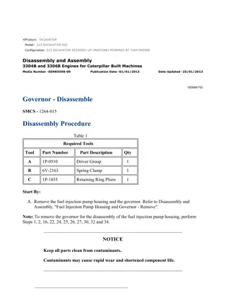
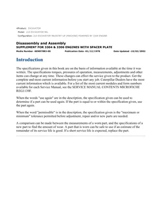
215 EXCAVATOR 14Z00649-UP (MACHINE) POWERED BY 3204 ENGINE(SEB... 1/10 Product: EXCAVATOR Model: 215 EXCAVATOR 14Z Configuration: 215 EXCAVATOR 14Z00649-UP (MACHINE) POWERED BY 3204 ENGINE Disassembly and Assembly 3204 VEHICULAR ENGINE FOR 215 EXCAVATOR Media Number -SENR2168-01 Publication Date -01/02/1982 Date Updated -11/10/2001 Governor SMCS - 1264-15; 1264-16 Disassemble Governor start by: a) remove fuel injection pump housing and governor https://127.0.0.1/sisweb/sisweb/techdoc/techdoc_print_page.jsp?returnurl=/sis... 2021/10/15
215 EXCAVATOR 14Z00649-UP (MACHINE) POWERED BY 3204 ENGINE(SEB... 2/10 NOTE: If it is desired to only remove the governor so the fuel injection pump housing can be disassembled do only Steps 1, 3, 5, 6, 12, and 13. 1. Remove cover (1). 2. Remove lever (2) and the key from the shaft. 3. Remove bolts (3) and cover (4) from the governor housing. 4. Remove O-ring seals (5) from the low and high idle adjustment screws. 5. Remove screw (6) from rack stop collar (7) and remove collar (7). Remove the spring from behind the collar. 6. Remove bolts (8) and remove governor housing (9) from the fuel injection pump housing. https://127.0.0.1/sisweb/sisweb/techdoc/techdoc_print_page.jsp?returnurl=/sis... 2021/10/15
215 EXCAVATOR 14Z00649-UP (MACHINE) POWERED BY 3204 ENGINE(SEB... 3/10 7. Remove high idle adjustment screw (11) and low idle adjustment screw (10) from the governor housing. Remove the high idle adjustment screw first. 8. Remove bolts (12) and torque control (13) from the governor housing. 9. Remove bolt (14) and the lock. Remove shaft (15) and lever assembly (16) from the governor housing. Pin (19) holds spring (17) in compression. Use caution to prevent injury when pin (19) is removed. Release the tension in spring (17) slowly. 10. Remove pin (19), spring (17) and plunger (18) from the lever assembly. https://127.0.0.1/sisweb/sisweb/techdoc/techdoc_print_page.jsp?returnurl=/sis... 2021/10/15
215 EXCAVATOR 14Z00649-UP (MACHINE) POWERED BY 3204 ENGINE(SEB... 4/10 11. Remove seal (21) from the governor housing. Use tooling (A) to remove the plug and bearings (20) from the governor housing. NOTE: If a replacement of spring guide (22) is necessary see SPECIAL INSTRUCTION Form No. SMHS7356 - USE OF 6V22 TOOL GROUP FOR REPLACEMENT OF GOVERNOR SPRING GUIDE. 12. Remove seat, washer, wave-washers and governor spring (23) from the weight assembly. Remove spring washer (26) from the weight assembly. 13. Remove bolts (24) and the lock that hold weight assembly (25) to the fuel injection pump housing. Pull the weight assembly out and to the side to disengage it from the rack. 14. Remove ring (27) and the dowel under the ring that holds seat (28) in place. 15. Remove seat (28), bolt (29) and spring (30) from the weight assembly. Remove washer (31) from spring (30). https://127.0.0.1/sisweb/sisweb/techdoc/techdoc_print_page.jsp?returnurl=/sis... 2021/10/15
215 EXCAVATOR 14Z00649-UP (MACHINE) POWERED BY 3204 ENGINE(SEB... 5/10 16. Remove guide (32), the two races and bearing from the sleeve. 17. Remove the second dowel (33) that holds sleeve (34) in place and remove the sleeve. 18. Remove valve (37) from the weight assembly and cylinder (35). 19. Remove lock (36) and make a separation of the weight assembly and cylinder (35). 20. Remove sleeve (38) and piston (39) from cylinder (35). Remove the O-ring seal from the sleeve. Assemble Governor NOTE: Put clean oil on all parts before assembly and be sure all oil passages are clear. https://127.0.0.1/sisweb/sisweb/techdoc/techdoc_print_page.jsp?returnurl=/sis... 2021/10/15
215 EXCAVATOR 14Z00649-UP (MACHINE) POWERED BY 3204 ENGINE(SEB... 6/10 1. Install the O-ring seal on sleeve (2). Install piston (1) in sleeve (2). Install sleeve (2) in cylinder (3). 2. Install cylinder (3) in weight assembly (4) and install lock (5) to hold them together. 3. Install valve (7) through the cylinder and install sleeve (6) on the valve with the second hole in the sleeve in alignment with the hold in the valve. Install dowel (8) to hold the sleeve on the valve. 4. Install larger race (9), bearing (10), smaller race (11) and guide (12) on sleeve (8). Put the hole in guide (12) in alignment with the first hole in sleeve (8). https://127.0.0.1/sisweb/sisweb/techdoc/techdoc_print_page.jsp?returnurl=/sis... 2021/10/15
Suggest: For more complete manuals. Please go to the home page. https://www.ebooklibonline.com If the above button click is invalid. Please download this document first, and then click the above link to download the complete manual. Thank you so much for reading
215 EXCAVATOR 14Z00649-UP (MACHINE) POWERED BY 3204 ENGINE(SEB... 7/10 5. Install washer (16) in spring (13). Install bolt (17) in seat (14). Put spring (13) and seat (14) in position on guide (12) with the hole in seat (14) in alignment with the hole in guide (12). Install dowel (18) through seat (14) and guide (12). Install ring (15) on the seat to hold the dowel in place. 6. Install the weight assembly on the fuel injection pump housing with piston (1) engaged over the groove in rack (19). Install lock (20) and the bolts that hold the weight assembly to the fuel injection pump housing. 7. Install spring washer (26) on the bolt as shown. 8. Install spring (25), one wave washer (24), flat washer (23), other wave washer (22) and seat (21) on the bolt as shown. 9. Put plunger (28) and spring (27) in position in lever assembly (30) and install pin (29) to hold the spring and plunger in place. https://127.0.0.1/sisweb/sisweb/techdoc/techdoc_print_page.jsp?returnurl=/sis... 2021/10/15
215 EXCAVATOR 14Z00649-UP (MACHINE) POWERED BY 3204 ENGINE(SEB... 8/10 10. Dimensions (X) and (Y) are controlled by the depths of bearings (32) and (33) in the governor housing. Install bearings (32) and (33) with tooling (A). Install lever assembly (30) and shaft (31) in the governor housing. With lever assembly (30) pushed against bearing (33) on the detent side, the clearance [dimension (Y)] between the guide for the governor spring and lever assembly (30) must be approximately 2.49 mm (.098 in.). Push lever assembly (30) against bearing (32) on the other side. The clearance [dimension (X)] between the guide for the governor spring and lever assembly must be approximately 3.40 mm (.134 in.). If the measurements are not correct, remove the lever assembly and the shaft and move the bearings as necessary to get the correct measurement. After the bearings are installed, there must be approximately .38 mm (.015 in.) end play in the lever assembly. Remove the shaft and lever assembly. 11. Install the plug on the detent side of the governor housing with tooling (A) to a depth of 2.3 0.5 mm (.091 0.20 in.). Install the lip type seal in the opposite side of the governor housing with tooling (A). Install the lip type seal with the lip toward the inside of the governor housing. 12. Put the lever assembly and shaft in position in the governor housing and install the bolt and lock in the lever assembly. 13. Assemble the torque control group as follows: https://127.0.0.1/sisweb/sisweb/techdoc/techdoc_print_page.jsp?returnurl=/sis... 2021/10/15
https://www.ebooklibonline.com Hello dear friend! Thank you very much for reading. Enter the link into your browser. The full manual is available for immediate download. https://www.ebooklibonline.com
 POWERED BY 3204")
 POWERED BY 3204")
 POWERED BY 3204")

 POWERED BY 3204")
 POWERED BY 3204")
 POWERED BY 3204")
 POWERED BY 3204")
 POWERED BY 3204")
 POWERED BY 3204")
 POWERED BY 3204")
 POWERED BY 3204")
 POWERED BY 3204")
 POWERED BY 3204")
 POWERED BY 3204")
 POWERED BY 3204")
 POWERED BY 3204")
 POWERED BY 3204")
 POWERED BY 3204")
 POWERED BY 3204")

 POWERED BY 3204")
 POWERED BY 3204")