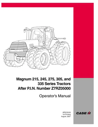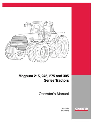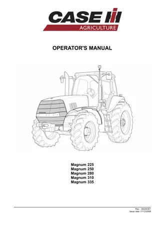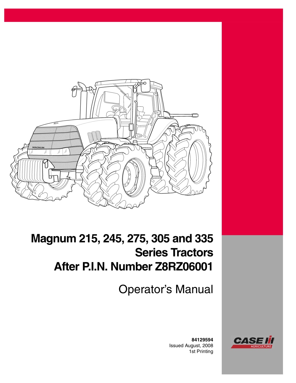
Case IH Magnum 215 245 275 305 and 335 Series Tractors (After Pin NumberZ8RZ06001) Operator’s Manual Instant Download (Publication No.84129594)
Please open the website below to get the complete manualnn//
Download Presentation

Please find below an Image/Link to download the presentation.
The content on the website is provided AS IS for your information and personal use only. It may not be sold, licensed, or shared on other websites without obtaining consent from the author. Download presentation by click this link. If you encounter any issues during the download, it is possible that the publisher has removed the file from their server.
E N D
Presentation Transcript
Magnum 215, 245, 275, 305 and 335 Series Tractors After P.I.N. Number Z8RZ06001 Operator s Manual 84129594 Issued August, 2008 1st Printing CNH America LLC, Racine, WI 53404 U.S.A. Printed in U.S.A.
Contents 1 GENERAL INFORMATION Personal safety............................................................................. 1-1 Proposition 65 .............................................................................. 1-2 Product identification ....................................................................... 1-3 Note to the Owner .......................................................................... 1-4 Tractor intended use........................................................................ 1-5 Manual storage............................................................................. 1-5 Product identification ....................................................................... 1-6 Component location ........................................................................ 1-8 2 SAFETY INFORMATION Safety rules................................................................................. 2-1 ROPS and CSF............................................................................. 2-5 SAFETY DECALS.......................................................................... 2-6 3 CONTROLS/INSTRUMENTS ACCESS TO OPERATOR S PLATFORM Tractor access.......................................................................... 3-1 OPERATOR S SEAT Overview ............................................................................... 3-2 Control identification.................................................................... 3-4 INSTRUCTOR S SEAT Overview ............................................................................... 3-7 FORWARD CONTROLS STEERING COLUMN .................................................................. 3-8 FRONT CONSOLE.................................................................... 3-11 PEDAL CONTROLS................................................................... 3-13 RH SIDE CONTROLS ARMREST CONSOLE ................................................................ 3-16 ARMREST COMPARTMENT.......................................................... 3-24 Adjusting the armrest console......................................................... 3-27 REARWARD CONTROLS FENDER CONSOLE .................................................................. 3-28 AUTOMATIC TEMPERATURE CONTROLS.......................................... 3-33 AUTOMATIC TEMPERATURE CONTROL SYSTEM ................................. 3-36 VENTILATION......................................................................... 3-37 OVERHEAD CONTROLS LAMPS ................................................................................ 3-39 EXTERIOR CONTROLS REAR FENDER ....................................................................... 3-40 INSTRUMENT CLUSTER Overview .............................................................................. 3-41 GAUGES .............................................................................. 3-42 DEDICATED DISPLAY ................................................................ 3-44 KEYPAD............................................................................... 3-46 STATUS AND WARNING ICONS ..................................................... 3-49 PROGRAMMABLE DISPLAY ......................................................... 3-51
DISPLAY SETTINGS.................................................................. 3-71 OPERATOR PREFERENCES......................................................... 3-82 ICON LEGEND........................................................................ 3-92 4 OPERATING INSTRUCTIONS COMMISSIONING THE UNIT Before starting the engine .............................................................. 4-1 STARTING THE UNIT NORMAL ENGINE STARTING......................................................... 4-4 Cold temperature operation ............................................................ 4-7 STOPPING THE UNIT STOPPING THE ENGINE............................................................. 4-10 MOVING THE UNIT Powershift transmission ............................................................... 4-11 Transmission default gears............................................................ 4-12 Setting default gears .................................................................. 4-16 Best practices for prolonged transmission life......................................... 4-19 Transmission disengages; neutral icon flashes ....................................... 4-20 Automatic productivity management (APM)........................................... 4-21 Mechanical front drive (MFD).......................................................... 4-30 Differential lock system................................................................ 4-34 Suspended axle ....................................................................... 4-37 Ride control............................................................................ 4-45 Constant engine speed................................................................ 4-48 Electronic end of row system.......................................................... 4-50 5 TRANSPORT OPERATIONS ROAD TRANSPORT Tractor warning lamps and SMV symbol ............................................... 5-1 Wide transport marker light............................................................. 5-2 Tractor warning lamps.................................................................. 5-4 Safe transport speed ................................................................... 5-5 Implement warning lamps and SMV symbol ........................................... 5-6 Safety chain ............................................................................ 5-7 SHIPPING TRANSPORT Securing the tractor for shipping ....................................................... 5-8 RECOVERY TRANSPORT Safety rules............................................................................. 5-9 TOWING THE TRACTOR ............................................................. 5-10 6 WORKING OPERATIONS GENERAL INFORMATION Overview ............................................................................... 6-1 REAR PTO Safety rules......................................................................... 6-2 Connecting the PTO................................................................ 6-5 Interchangeable PTO shaft......................................................... 6-6 Reversible PTO shaft.............................................................. 6-12
https://www.ebooklibonline.com Hello dear friend! Thank you very much for reading. Enter the link into your browser. The full manual is available for immediate download. https://www.ebooklibonline.com
PTO operation..................................................................... 6-14 PTO fender switch operation ...................................................... 6-18 Auto PTO operation ............................................................... 6-19 THREE POINT HITCH Identification ....................................................................... 6-23 Link adjustment.................................................................... 6-24 Hitch high clearance adjustment .................................................. 6-28 Hydraulic links ..................................................................... 6-31 Sway limiter adjustment ........................................................... 6-32 Lower link block adjustment ....................................................... 6-33 Mechanical float adjustment....................................................... 6-34 Hitch quick coupler - Category III/IIIN ............................................. 6-35 Hitch quick coupler - Category IVN................................................ 6-40 Hitch operation .................................................................... 6-44 Hitch remote switch operation..................................................... 6-50 Position control operation ......................................................... 6-51 Load control operation............................................................. 6-53 Slip control operation.............................................................. 6-55 Hitch set point ..................................................................... 6-58 DRAWBARS AND TOWING ATTACHMENTS Safety rules........................................................................ 6-61 Drawbar capacity/position ......................................................... 6-61 Adjusting the drawbar ............................................................. 6-66 AUXILIARY POWER CONNECTIONS Auxiliary power and lighting ....................................................... 6-68 Cab power connections ........................................................... 6-70 HYDRAULIC REMOTE CONTROL VALVES Valve couplers and connections................................................... 6-72 Motor return circuit ................................................................ 6-75 Power beyond circuit .............................................................. 6-76 Overview .......................................................................... 6-78 Operating the controls............................................................. 6-79 Changing the functional mode..................................................... 6-82 Remote hydraulic auto mode...................................................... 6-86 Auto depth control ................................................................. 6-89 BALLASTING THE TRACTOR Guidelines ......................................................................... 6-92 Tire load and inflation charts ...................................................... 6-97 Weights, cast metal and liquid.................................................... 6-105 Wheel slip and power hop performance ......................................... 6-113 MECHANICAL FRONT DRIVE (MFD) AXLES Tire combinations and tread positions............................................ 6-116 Steering and oscillation stops .................................................... 6-123 REAR AXLE Rear wheel installation ........................................................... 6-131 Rear wheel tread settings ........................................................ 6-134
7 MAINTENANCE GENERAL INFORMATION Safety rules............................................................................. 7-1 Opening the hood ...................................................................... 7-2 Battery access and service............................................................. 7-4 Tire and rim service..................................................................... 7-5 Tractor jacking points................................................................... 7-7 Capacities .............................................................................. 7-9 Consumables.......................................................................... 7-11 Electrical component location ......................................................... 7-15 Electrical system specification......................................................... 7-19 Maintenance chart notes .............................................................. 7-20 MAINTENANCE CHART Maintenance Chart .................................................................... 7-20 At warning message display Air filter service icon/message......................................................... 7-22 First 10 to 50 hours Differential and planetary oil........................................................... 7-23 Wheel bolt torque...................................................................... 7-24 Weight bolt torque ..................................................................... 7-25 Every 10 hours or daily Engine oil level ........................................................................ 7-26 Transmission oil level.................................................................. 7-27 Engine coolant level ................................................................... 7-28 Engine auxiliary fuel filter.............................................................. 7-29 Air tank - Drain fluid ................................................................... 7-30 Rear hitch and front axle .............................................................. 7-31 Every 50 hours Engine primary fuel filter............................................................... 7-32 Every 300 hours Battery water level (Note E) ........................................................... 7-33 Engine air intake hoses................................................................ 7-34 Engine coolant level - deaeration tank ................................................ 7-35 Engine oil and filter .................................................................... 7-36 Wheel bolt torque...................................................................... 7-38 Weight bolt torque ..................................................................... 7-39 Front axle (Note A) .................................................................... 7-40 Rear hitch (Note A).................................................................... 7-47 Fuel tank............................................................................... 7-49 Differential and planetary oil level (Note B)............................................ 7-50 Transmission oil pressure oil pressure ................................................ 7-52 Reversible 1000 RPM PTO shaft (Note D) ............................................ 7-54 Every 600 hours Engine coolant antifreeze protection .................................................. 7-55 Engine coolant filter ................................................................... 7-56
Engine coolant hoses and clamps..................................................... 7-57 Engine primary fuel filter............................................................... 7-58 Changeable PTO internal splines ..................................................... 7-60 Every 1200 hours or annually Differential and planetary oil........................................................... 7-61 Engine air filters ....................................................................... 7-65 Engine air precleaner.................................................................. 7-69 Every 1500 hours Transmission oil ....................................................................... 7-70 Transmission oil filter .................................................................. 7-72 Regulated transmission filter .......................................................... 7-73 Every 2100 hours Engine coolant......................................................................... 7-74 Fuel injector nozzles (Note C)......................................................... 7-77 Engine valve adjustment (Note C)..................................................... 7-77 Every 3000 hours Engine vibration damper (Note C)..................................................... 7-78 As required Vehicle fire prevention................................................................. 7-79 Cab air filter............................................................................ 7-80 Engine primary air filter................................................................ 7-83 Grille screen and radiator area ........................................................ 7-86 Fuel tank vent filter .................................................................... 7-88 Transmission clutch and accumulator................................................. 7-88 Tire pressure .......................................................................... 7-88 Fan belt................................................................................ 7-89 Spark arresting muffler ................................................................ 7-90 Remote valve collection bottle......................................................... 7-91 Engine auxiliary fuel filter.............................................................. 7-92 Cab fabric and carpet.................................................................. 7-94 Seat belt ............................................................................... 7-95 STORAGE TRACTOR STORAGE............................................................. 7-96 REMOVAL FROM STORAGE..................................................... 7-96 ELECTRICAL SYSTEM Radio or audio system................................................................. 7-97 Battery removal and installation ....................................................... 7-98 Auxiliary battery connections......................................................... 7-100 Head light - Replace.................................................................. 7-101 Flood and work light .................................................................. 7-107 Fender tail light and warning light .................................................... 7-109 Roof front warning and work light .................................................... 7-111 Roof rear warning light ............................................................... 7-114 High intensity work light .............................................................. 7-116 Wide transport marker light........................................................... 7-118 Rotating beacon light................................................................. 7-119 Interior light - Replace ................................................................ 7-120
8 TROUBLESHOOTING ALARM(S) Display warnings ................................................................... 8-1 9 SPECIFICATIONS ENGINE - General specification............................................................ 9-1 POWER TRAIN - General specification .................................................... 9-3 TRAVELLING - Speeds .................................................................... 9-6 Vehicle dimensions and shipping weight .................................................. 9-15 Maximum operating weight................................................................ 9-17 10 ACCESSORIES Front wheel fenders ....................................................................... 10-1 Farming system displays .................................................................. 10-7 Chemical tank mounting.................................................................. 10-10 Loader connection and operation ........................................................ 10-12 Trailer brake connections................................................................. 10-13 General accessories...................................................................... 10-16
GENERAL INFORMATION - 1 1 - GENERAL INFORMATION Personal safety THIS SAFETY ALERT SYMBOL INDICATES IMPORTANT SAFETY MESSAGES IN THIS MANUAL. WHEN YOU SEE THIS SYMBOL, CAREFULLY READ THE MESSAGE THAT FOLLOWS AND BE ALERT TO THE POSSIBILITY OF DEATH OR SERIOUS INJURY. Throughout this manual and on the machine s safety decals, you will find precautionary statements: DANGER< WARNING or CAUTION followed by special instructions or ISO two panel safety pictorial symbols. These precau- tions are intended for your personal safety. Failure to follow the DANGER, WARNING or CAUTION instructions may result in death or serious bodily injury. DANGER, WARNING or CAUTION are defined as follows: DANGER: Indicates an immediate hazardous situation that, if not avoided, will result in death or serious injury. The color associated with Danger is RED. WARNING: Indicates a potentially hazardous situation that, if not avoided, could result in death or serious injury. The color associated with Warning is ORANGE. CAUTION: Indicates a potentially hazardous situation that, if not avoided, could result in minor or moderate injury. It may also be used to alert against unsafe practices. The color associated with Caution is YELLOW. ISO two panel pictorial symbol decals are defined as follows: The first panel indicates the nature of the hazard. The second panel indicates the appropriate avoidance of the hazard Background color is YELLOW. Prohibition symbols such as and if used are RED. WARNING IMPROPER OPERATION OF THIS MACHINE CAN CAUSE DEATH OR SERIOUS INJURY. BEFORE USING THIS MACHINE, MAKE CERTAIN THAT EVERY OPERATOR: Is instructed in safe and proper use of the machine. Reads and understands the Manual(s) pertaining to the machine. Reads and understands ALL Safety Decals on the machine. Clears the area of other persons. Learns and practices safe use of machine controls in a safe, clear area before operating this machine on a job site. It is your responsibility to observe pertinent laws and regulations and follow CNH America LLC instructions on machine operation and maintenance. 1 - 1
GENERAL INFORMATION - 1 CNH America LLC technical manuals Manuals are available from your Dealer for the operation, service and repair of your machine. For prompt convenient service, contact your Dealer for assistance in obtaining the manuals for your machine. YouDealercanexpediteyourorderforOperatorsManuals, PartsCatalogs, RepairManualsandmaintenancerecords. Always give the Machine Name, Model and P.I.N. (product identification number) of your machine so your Dealer can provide the correct manuals for your machine. The company is continually striving to improve its products and therefore reserves the right to make improvements and changes when it becomes practical and possible to do so, without incurring any obligation to make changes or additions to the equipment sold previously. All data given in this manual is subject to production variations. IMPORTANT: OPERATING AND SERVICE MES- SAGES DISPLAYED ON THE ELECTRONIC OPERATING PANEL MAY VARY FROM WHAT IS SHOWN IN THE OP- ERATOR S MANUAL. SHOULD THIS OCCUR ADHERE TO THE LATEST INSTRUCTION ON THE ELECTRONIC OPERATING PANEL. Dimensions and weights are approximate only and the illustrations do not necessarily show the machine in standard condition. For exact information about any particular machine, please consult your dealer. Proposition 65 1 RCIL08CCH001EAA 1 - 2
GENERAL INFORMATION - 1 Product identification 1 RCPH07CCH014FAB 2 RCPH08CCH004FAB 1 - 3
GENERAL INFORMATION - 1 Note to the Owner This manual contains important information about the safe operation, adjustment and routine maintenance of your Magnum series tractor. The manual is divided into ten chapters as outlined in the table of contents. Refer to the index at the end of this manual for locating specific items about your tractor. This Operator s Manual is to be stored in the manual com- partment equipped on this machine. Make sure this man- ual is in good condition. Contact your dealer to obtain ad- ditional manuals. Contact your dealer for any further in- formation or assistance about your machine. Your dealer has approved service parts. Your dealer has technicians with special training that know the best methods of repair and maintenance for your tractor. Do NOT operate or permit anyone to operate or service this machine until you or the other persons have read this manual. Use only trained operators who have demon- strated the ability to operate and service this machine cor- rectly and safely. 1 - 4
GENERAL INFORMATION - 1 Tractor intended use Magnum series tractors with standard equipment and au- thorizedattachments, areintendedtobeusedforcustom- ary farming, land leveling and related agriculture opera- tions. Installation of utility (dozer) blades, tile plows, or push bars on the tractor is not recommended. Any tractor damage resulting from the installation and/or use of such equipment is not covered by the tractor warranty. Consult an authorized dealer or CNH America LLC on changes, additions or modifications that can be required for this machine to comply with various regulations and safety requirements. Unauthorized modifications will cause serious injury or death. unauthorized modifications is responsible for the conse- quences. Anyone making such Manual storage 1 RCPH08CCH002FAB Keep the Operator s Manual in the storage compartment provided on your tractor. The Operator s Manual must be available for use by all operators. The right hand and left hand side of the tractor used in this manual are the same as your right hand and left hand when sitting in the tractor seat looking forward. 1 - 5
GENERAL INFORMATION - 1 Product identification Tractor model and product identification number Model : PIN NOTE: Located on right hand front casting. 1 RCPH08CCH486AAB Roll over protection system (ROPS) serial number NOTE: Located on the right hand cab floor. 2 RCPH08CCH482AAB Engine serial number NOTE: Located on the front left hand side of the engine.. 3 RCPH08CCH479AAB 1 - 6
GENERAL INFORMATION - 1 Transmission serial number NOTE: Located on the right hand side of the transmission (speed housing) behind the fuel tank and to the left of the ground stud. 4 RCPH08CCH483AAB Axle serial number MFD axle: Located on the rear right hand side of the axle housing (1) (shown). Saddle suspended axle: Located on the rear right hand side of the axle housing (not shown). Scissors suspended axle: Located on the front right hand side of the axle housing (not shown). 5 RCPH08CCH484AAB 1 - 7
GENERAL INFORMATION - 1 Component location 1 RCPH08CCH004FAB 5. Hood 6. Front weights 7. Exhaust stack 8. Wide transport marker 9. Amber warning lamps 10. Work lamps 11. Road/work lamps 12. HID lamp 1. ROPS cab 2. Hand rail 3. Steps 4. Fuel tank 13. Amber reflector 1 - 8
GENERAL INFORMATION - 1 2 RCPH08CCH005FAB 5. Drawbar 6. Amber warning lamps 7. Tail/brake lamp 8. SMV symbol 9. Wide transport marker 10. Red reflector 11. Orange reflector 12. Roof/fender and HID work lamps 1. ROPS cab 2. Rear view mirror 3. Rear hitch 4. Power takeoff (PTO) 1 - 9
GENERAL INFORMATION - 1 1 - 10
SAFETY INFORMATION - 2 2 - SAFETY INFORMATION Safety rules Understand that your safety and the safety of other persons is measured by how you service and operate this ma- chine. Know the positions and operation of all controls before you try to operate. MAKE SURE YOU CHECK ALL CONTROLS IN A SAFE AREA BEFORE STARTING YOUR WORK. READ THIS MANUAL COMPLETELY and make sure you understand the controls. All equipment has limits. Make sure you understand the speed, brakes, steering stability and load characteristics of this machine before you start to operate. The safety information given in this manual does not replace safety codes, insurance needs, federal, state and local laws. Make sure your machine has the correct equipment needed by the local laws and regulations. CNH America LLC is continuing to work for your safety by making tractors with better protection and by providing these rules for safe operation. Failure to comply could result in death or serious injury. (M1219) Before starting the engine, be sure all operating con- trols are in neutral or park lock position. This will elim- inate accidental movement of the machine or start up of power driven equipment. (M106E) Collision of high speed road traffic and slow moving machines can cause personal injury or death. roads, use flasher/lights according to local laws. Keep slow moving vehicle (SMV) emblem visible. Pull over to let faster traffic pass. Slow down and signal before turning off. (R110E) On Operate controls only when seated in the operators seat. (M137A) Securely fasten your seat belt. The seat belt can in- crease your safety if it is used and maintained. Never wear a seat belt loosely or with slack in the belt sys- tem. Never wear the belt in a twisted condition or pinchedbetweentheseatstructuralmembers, Inspect seat belt webbing, buckle and retractors to ensure they are not damaged. If damage is apparent, re- pair before operating the machine . Failure to comply could result in death or serious injury. (M1284) For speeds up to 16 km/h (10 mph), make sure that the weight of a trailed vehicle that is not equipped with brakes does NOT EXCEED 1.5 times the Tractor weight. For speeds up to 40 km/h (25 mph), make sure that the weight of the trailed vehicle that is not equipped with brakes, does NOT EXCEED the weight of the Tractor. Stopping distance increases with in- creasing speed as the weight of the towed load in- creases, especially on hills and slopes. (M814A) A frequent cause of death or serious injury is persons falling off machinery and being run over. Keep cab door closed. Instructional seat is used only for in- structing or service diagnosing only. DO NOT permit others to ride, especially children. Seat belt must be worn at all times. (M488C) Brake pedals must be locked together for road travel. This will insure uniform brake application and maxi- mum stopping ability. Failure to comply could result in death or serious injury. (R112A) Stay off slopes too steep for safe operation. down before you start up or down a hill with a heavy load. Avoid free wheeling. Shift Extra weight and bad traction conditions such as mud or ice increase your stopping distance. Remember that liquid in the tires, weights on the machine or wheels, tanks filled with fertilizer, herbicides or in- secticides - all these add weight and increase the distance you need in which to stop. (R138B) Do not drive on roads, or at high speed anywhere, with the differential lock engaged. Difficult steering will occur, and can result in an accident. In field operation, use the differential lock for traction improvement, but release for turning at row ends. (M116A) Before leaving the tractor, stop the engine, put all con- trols in neutral or park lock position, remove the key from the key switch. (R301B) Travel speed should be such that complete control andmachinestabilityismaintainedatalltimes. Where possible, avoid operating near ditches, embankments and holes. Reduce speed when turning, crossing slopes, and on rough, slick, or muddy surfaces. Fail- ure to comply could result in death or serious injury. (M109B) If the tractor engine stalls, hydraulic pressure drops, and the brake pedals can be pushed to the floor. Activating BOTH pedals will engage the park brake. (M768) PTO driven machinery can cause serious injury. Be- fore working on or near the PTO shaft, or servicing or clearing the driven machine, put the PTO lever in the DISENGAGEposition and STOP the engine. (R154A) Do not exceed implement transport speed or the speed rating on the implement tires. implements Operator s Manual for specifications. Review the 2 - 1
Suggest: If the above button click is invalid. Please download this document first, and then click the above link to download the complete manual. Thank you so much for reading
SAFETY INFORMATION - 2 Whenever a PTO driven machine is in operation, the PTO guard must be in place for most operations to prevent injury to the operator or bystanders. Where attachments, such as pumps, are installed on the PTO shaft (especially if the tractor PTO guard is moved up- ward or removed), extended shielding equivalent to the PTO guard must be installed with the attachment. Install the PTO guard to its original position immedi- ately when the attachment is removed. (R273A) Do not pull with elastic tow ropes. Elastic tow rope stores energy. Sudden release may cause injury or death. (M425) Young children should not be permitted to operate or ride the tractor under any circumstances. (M630) Do not tamper with the ballast on the front or rear High Intensity Discharge Lamps as it contains high voltage. Personal injury or death can occur. (M639) ALWAYS sound horn before starting the machine. Make sure working area is clear of other persons, pets, tools, etc. before you start operating this ma- chine. NEVER allow anybody in work area during machine operation. (M804) When doing stationary PTO work and dismounting from the tractor with the PTO running, keep clear of all moving parts as they are a potential safety hazard. (R127A) Never operate the engine in a closed building. Proper ventilation is required under all circumstances. (R142A) To prevent tractor movement, always apply the park brake whenever the tractor is parked with the engine running. The park brake is applied automatically when the engine is shut down. (M627) Never refuel the machine when the engine is hot or running. Never smoke while refueling. (R139C) Always start the engine from the operator s seat. Never attempt to bypass start, the tractor may sud- denly start and move resulting in serious or fatal injury. (M787) Check and service cooling system according to the maintenance instructions. Hot coolant can spray out if the deaeration tank cap is removed while system is hot. To remove the deaeration tank cap, let system cool, turn to first notch, then wait until all pressure is released. Scalding can result from fast removal of the cap. (R141C) This tractor is equipped with a spring applied mechan- ical front wheel drive (MFD) clutch and a front axle limited slip differential. Even with the MFD engaging switch in the Off position, the front axle clutch can pro- pel both front wheels if any of the following conditions occur: Hydraulic oil or diesel fuel leaking under pressure can penetrate the skin and cause infection or other injury. To Prevent Personal Injury: 1. The engine is turned off. Relieve all pressure before disconnecting fluid lines. 2. The engine is stopped when the rear wheels are still coasting. Before applying pressure, make sure all connec- tions are tight and components are in good condi- tion. 3. Any interruption in the clutch operating hydraulic system flow or pressure or in the electrical controls for clutch operation. Never use your hand to check for suspected leaks under pressure. 4. Both brakes are applied. For these reasons, the following service procedures must be followed: Use a piece of cardboard or wood for this purpose. If injured by leaking fluid, see your doctor immedi- ately. (R149B) Before rotating the rear wheels of a MFD tractor (if you are using engine power with the rear wheels supported off the ground), one of the following pro- cedures must be done to prevent an accidental tractor movement. Rear upset can result if pulling from wrong location on tractor. Hitch only to the drawbar. Use three point hitch only with the implements designed for its use - not as a drawbar. Jack up and support BOTH front wheels com- pletely off the ground. Do not look directly into the front or rear High Intensity Discharge Lamps. Eye damage can occur. (M638) OR If the tractor stalls, hydraulic pressure drops, and the brake pedals can be pushed to the floor. Activating BOTH pedals will engage the park brake. (M768) Disconnect the front wheel drive shaft. Doing one of these two procedures will insure that engage- ment of the MFD clutch will not result in tractor movement. (R292B) Clean tractor of field trash daily or more frequently depending upon conditions. Trash accumulation on the tractor can cause damage and fire. (M791) To avoid possible eye damage from microwave sig- nals emitted by the radar sensor, do not look directly into the sensor face. (M788) Always keep the cab windows and rear view mirrors clean to provide the best all around visibility while op- erating the tractor. (R416) 2 - 2
https://www.ebooklibonline.com Hello dear friend! Thank you very much for reading. Enter the link into your browser. The full manual is available for immediate download. https://www.ebooklibonline.com

