Casting Processes and Solidification: Metals, Ceramics, Polymers
Lecture 2 by Dr. Suha K. Shihab explores casting processes classified by materials - metals, ceramics, polymers, and polymer matrix composites. It delves into the principles, preparation of molds, patterns, and materials used. Different types of patterns, pattern allowances, and the importance of pattern materials are discussed. The lecture covers the significance of solidification, defects, and inspection in casting operations.

Download Presentation

Please find below an Image/Link to download the presentation.
The content on the website is provided AS IS for your information and personal use only. It may not be sold, licensed, or shared on other websites without obtaining consent from the author.If you encounter any issues during the download, it is possible that the publisher has removed the file from their server.
You are allowed to download the files provided on this website for personal or commercial use, subject to the condition that they are used lawfully. All files are the property of their respective owners.
The content on the website is provided AS IS for your information and personal use only. It may not be sold, licensed, or shared on other websites without obtaining consent from the author.
E N D
Presentation Transcript
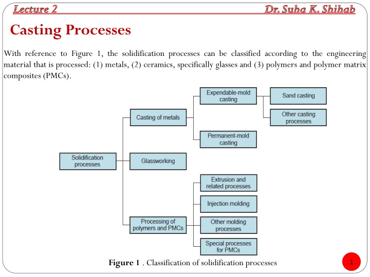
Lecture 2 Dr. Suha K. Shihab Casting Processes With reference to Figure 1, the solidification processes can be classified according to the engineering material that is processed: (1) metals, (2) ceramics, specifically glasses and (3) polymers and polymer matrix composites (PMCs). 1 Figure 1 . Classification of solidification processes
Lecture 2 Dr. Suha K. Shihab Casting Processes Casting is a process in which molten metal flows by gravity or other force into a mold where it solidifies in the shape of the mold cavity. It is one of the oldest manufacturing processes. The principle of casting seems simple: melt the metal pour it into a mold let it cool and solidify A successful casting operation needs a knowledge in the following areas: 1. Preparation of mould and patterns 2. Melting and pouring of the liquefied metal 3. Solidification and further cooling to room temperature 4. Defects and inspection Casting includes both the casting of ingots and the casting of shapes. The term ingot is usually associated with the primary metals industries; it describes a large casting that is simple in shape and intended for subsequent reshaping by processes such as rolling or forging. Shapecasting involves the production of more complex geometries that are much closer to the final desired shape of the part or product. 2
Lecture 2 Dr. Suha K. Shihab Patterns and Mould A pattern is a replica of the object to be cast, used to prepare the cavity into which molten material will be poured during the casting process. Patterns may be made of wood, metal, plastics or other materials. A mold or mould is a hollowed-out block that is filled with a liquid or pliable material such as plastic, glass, metal, or ceramic raw material. The liquid hardens or sets inside the mold, adopting its shape. Materials of Pattern The material of pattern should be: 1. Easily worked, shaped and joined. 2. Light in weight. Strong, 3. hard and durable. 4. Resistant to wear and abrasion . 5. Resistant to corrosion, and to chemical reactions. 6. Dimensionally stable and unaffected by variations in temperature and humidity. 7. Available at low cost. 3
Lecture 2 Dr. Suha K. Shihab Made of: wood, metal, plastics, plaster and synthetic materials Wood - Cheap, easily machined but prone to warping, swelling (moisture), unstable, wears. Used for small runs. Metal - more expensive but stable, accurate, durable. Typically aluminium, cast iron or steel. Large runs and elevated pressure and/or temperature moulding process Plastic - Epoxy and Polyurethane. More common now. Easy preparation, stable and durable relative to wood. Cast & machined, easily repaired, can be reinforced/backed Expendable (single-use) patterns: Wax - used for investment casting. Wax formulated for melting point, viscosity, Ash content etc. Melted out (mostly) before casting EPS - Expanded Polystyrene, heated (steam) to completely fill mould and bond beads. Pattern is burnt out by molten metal. 4
PATTERN ALLOWANCES Pattern allowance is the excess in dimensions where the pattern always made somewhat larger than final job to be produced. 1. Is the amount by which the mold must be made larger relative to the final casting size. It will take care of contractions of a casting which occurs as the metal cools to room temperature. Liquid shrinkage refers to the reduction in volume when the metal changes from liquid to solid state at the solid temperature. Riser which feed the liquid metal to the casting is provided in the mould to compensate for this. Solid shrinkage is the reduction in volume caused, when metal loses temperature in solid state. The shrinkage allowance is provided to take care of this reduction. Shrinkage allowance The actual value of shrinkage depends on various factors specific to a particular casting: 1. the actual component of the alloy cast, 2. mould materials used, mould design, 3. complexity of the pattern and the component size. The shrinkage allowance depends on the coefficient of thermal expansion of the material ( ). A simple relation indicates that higher the value of , more is the shrinkage allowance. The exact amount of this shrinkage compensation, which depends on the metal that is being cast, can be estimated by the equation l= l T T is the difference between the freezing temperature and room temperature. 5
Lecture 2 Dr. Suha K. Shihab Figure 2 Shrinkage of a cylindrical casting solidification and cooling: (0) starting level of molten metal immediately pouring; (1) reduction in level caused by liquid during cooling; (2) reduction in height and formation of shrinkage cavity solidification shrinkage; (3) Further reduction in height and diameter due to thermal during cooling of the solid metal. during after contraction caused by contraction 6
Lecture 2 Dr. Suha K. Shihab 2.Draft allowance At the time of withdrawing the pattern from the sand mould, the vertical faces of the pattern are in continual contact with the sand, which may damage the mould cavity, as shown in Fig.3 (a). Making the vertical surfaces of the pattern into inclined surfaces is called asDraft Allowance Fig.3 (b). Fig.3Draft Allowance 3. Machining or Finish Allowance Tolerances achievable in many casting processes are insufficient to meet functional needs in many applications. Sand casting is the most prominent example of this deficiency. In these cases, portions of the casting must be machined to the required dimensions. Almost all sand castings must be machined to some extent in order for the part to be made functional. Therefore, the extra dimension provided on the casting and it will be removed by machining after the casting has been completed is called as Machining Allowance. Typical machining allowances for sand castings range between 1.5 mm and 3 mm. 7
Lecture 2 Dr. Suha K. Shihab 4. Shake or Rapping Allowance Before withdrawal from the sand mould, the pattern is rapped all around the vertical faces to enlarge the mould cavity slightly which facilitates its removal. To maintain the required size of the casting, the original size of the pattern has to be reduced by an amount called asShake Allowance. It is a negative allowance and is to be applied only to those dimensions which are parallel to the parting plane. One way of reducing this allowance is to increase the draft which can be removed during the subsequent machining. 5.Distortion Allowance A metal when it has just solidified is very weak and therefore is likely to be distortion prone. This is particularly so for weaker sections such as V, U sections. The foundry practice should be to make extra material provision for reducing the distortion. Alternatively, the shape of pattern itself should be given a distortion of equal amount in the opposite direction of the likely distortion direction. This can be done by trial and error basis. The amount by which the legs are bending Inverse is called as Distortion or Bending allowance. Figure 4 Distortion or Bending allowance. 8
Lecture 2 Dr. Suha K. Shihab Types of Patterns The common types of patterns are: a) Solid (Single piece) pattern b) Split piece pattern c) Match pattern d) Cope and Drag pattern Figure 5 : Solid or Single piece, Split, Match-plate, Cope and Drag Pattern 9
Lecture 2 Dr. Suha K. Shihab Solid (Single piece ) pattern: This is the simplest type of pattern, exactly like the desired casting. Used for producing a few large castings. Determining the location of the parting line between the two halves of the mold for a solid pattern can be a problem, and incorporating the gating system and sprue into the mold is left to the skill of the foundry worker. Consequently, solid patterns are generally limited to very low production quantities. Split pattern: These patterns are split along the parting plane (which may be flat or irregular surface) to facilitate the extraction of the pattern out of the mould before the pouring operation. For a more complex casting, the pattern may be split in more than two parts. Used when patterns cannot be made as a single piece Match plate pattern: The two pieces of the split pattern are attached to opposite sides of a wood or metal plate. Holes in the plate allow the top and bottom (cope and drag) sections of the mold to be aligned accurately. The gates and runners are also mounted on the match plate, so that very little hand work is required. Therefore, they are suitable for higher production quantities Cope and drag pattern: are similar to match-plate patterns except that split pattern halves are attached to separate plates, so that the cope and drag sections of the mold can be fabricated independently, instead of using the same tooling for both. They are also suitable for higher production quantities. 10
Lecture 2 Dr. Suha K. Shihab CORES A coreis a full-scale model of the interior surfaces of the part. Cores are inserted into the mold cavity prior to pouring, so that the molten metal will flow and solidify between the mold cavity and the core to form the casting s internal surfaces. Cores are generally made of sand, metals, plaster, and ceramics. As with the pattern, the actual size of the core must include allowances for shrinkage and machining. Figure 6( a) Core held in place in the mold cavity by chaplets, (b) possible chaplet design, and (c) casting with internal cavity. 11
Lecture 2 Dr. Suha K. Shihab MOLDS The Moldcontains a cavity whose geometry determines the shape of the cast part. Types of Molding Materials Casting processes divide into two broad categories, according to type of mold used: 1. An expendable mold: means that the mold in which the molten metal solidifies must be destroyed in order to remove the casting. These molds are made out of sand, plaster, ceramic, or similar materials, whose form is maintained by using binders of various kinds. Sand casting is the most prominent example of the expendable-mold processes. 2. A permanent mold : is one that can be used over and over to produce many castings. It is made of metal that can withstand the high temperatures of the casting operation. In permanent-mold casting, the mold consists of two (or more) sections that can be opened to permit removal of the finished part. Die casting is the most familiar process in this group. 12
Lecture 2 Dr. Suha K. Shihab Types of Molding Operations To accomplish a casting operation, there are two types of molds: (a) Open mold, the liquid metal is simply poured until it fills the open cavity. (b) Closed mold, a passageway, called the gating system, is provided to permit the molten metal to flow from outside the mold into the cavity. Figure 7 Two forms of mold: (a) open mold, simply a container in the shape of the desired part; and (b) closed mold, in which the mold geometry is more complex and requires a gating system (passageway) leading into the cavity. 13