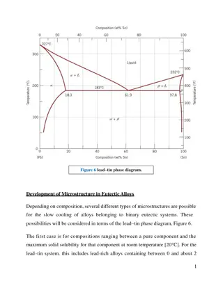
Advancements in Nuclear Alloys for Rapid Deployment
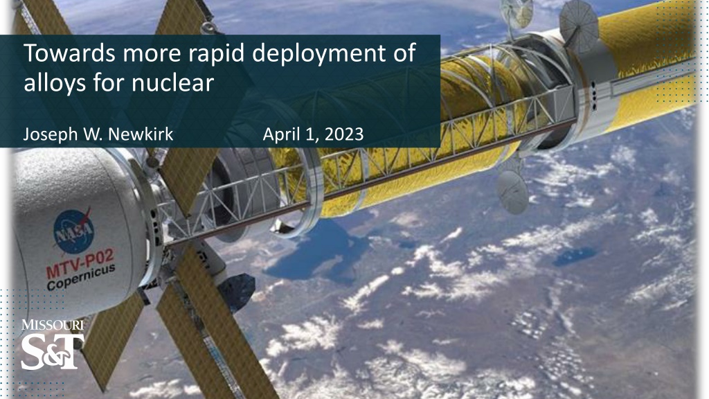
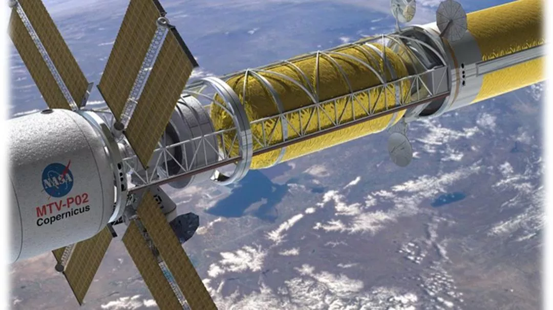


Towards more rapid deployment of
alloys for nuclear
Joseph W. Newkirk
April 1, 2023


>
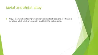
The need for “Advanced Metals and Alloys”
>
New alloy development
>
High-throughput development
>
Conclusions
Outline
1.
Specific request
2.
Specific request
3.
Specific request
4.
Specific request
5.
Specific request
6.
Specific request
7.
Specific request
8.
Specific request
9.
Specific request
10.
Advanced materials
Recent priority project calls
1.
Specific request
2.
Specific request
3.
Specific request
4.
Specific request
5.
Specific request
6.
Specific request
7.
Specific request
8.
Specific request
9.
Specific request
10.
Advanced materials
Recent priority project calls
NASA
DOE
ARL
AFOSR
Etc.
>
For millennia metallurgy was an art
–
Mix different ingredients and test
–
Art was learned and passed down
–
Often superior metallurgy was state secret
>
Until microscopes little understanding of science
Alchemy
>
Transition metals have large, nearly spherical electron shells
>
Lowest energy state is maximize nearest neighbors
>
Results in high densities of metals
>
Non-directional atomic bonding allows movement
>
Defects (dislocations) allow deformation without cracking at
lowered strengths
>
Dislocations can lower strength of metal >100x
Materials Science
>
Stopping dislocations makes metal brittle
>
Hindering dislocation strengthens metal and retains some
ductility
>
Metallurgists add 2
nd
phases to hinder dislocations
>
Removing phases allows fabrication
>
Restoring phases after fabrication locks strength into
component
Materials Engineering
>
Higher temperatures
>
Harsher environments
>
Metal behavior at high temperature?
–
What is high?
–
~50% of T
m
, homologous Temp
Materials for Extreme Environments
193
27
590
549
1563
>
Higher temperatures
>
Harsher environments
>
Metal behavior at high temperature?
–
What is high?
–
50% of T
m
, homologous Temp
>
Now creep matters, not strength doesn’t
>
Nickel alloys have high temperature use
>
Refractory metals highest
Materials for Extreme Environments
193
27
590
549
1563
>
Cost soars for hi T alloys
>
Compare Al to Co
>
Look at steel vs nickel
>
Later will mention Ta
–
$170/lb
Materials for Extreme Environments
>
Cost includes several factors
–
Material
–
Fabrication
–
Heat treatment
–
Secondary treatments
–
Market forces
Materials for Extreme Environments
Reactor steels
Gillemot, F. Review on Steel Enhancement for Nuclear RPVs. Metals 2021, 11, 2008.
>
Low alloy steels form pressure vessel by forging
>
Inner surface clad with stainless steel by welding
RPV structure
Štefan, J. et al. Microstructure and Failure Processes of Reactor Pressure Vessel
Austenitic Cladding. Metals 2021, 11, 1676.
>
Over time steel properties change
>
Increased hardness is usually accompanied by lower fracture
toughness
Reactor steel degradation
Ulbricht, A., et al. Effect of Neutron Flux on an Irradiation-Induced Microstructure and
Hardening of Reactor Pressure Vessel Steels. Metals 2022, 12, 369
Fast neutrons and heavy ions produce
cascade displacements
Electron irradiations create single Frenkel
defects (point defects of interstitials and
vacancies)
Low energy protons and light ions create
similar defects as electrons
Diffusion of transmutation products
Helium & Hydrogen (embrittlement
)
Irradiation damage process
Irradiation damage process
>
High temperatures
>
High neutron fluences
>
Corrosive cooling fluids
>
High pressure
>
Long lifetimes
Advanced reactor concepts
Operating temperature = 300 – 1000
o
C
Neutron energy < 1 – 3 MeV
Dose range = ~ 30 – 200dpa
Time of operation – 10s of years
Reactor pressure vessel alloy
Normal development cycle
1.
Conceive
2.
Experimental testing
3.
Irradiation testing*
4.
Optimize
5.
Transition to full scale production*
6.
Certify
•
Cycle is optimistically 20 years
Reactor pressure vessel alloy
Normal development cycle
1.
Conceive
2.
Experimental testing
3.
Irradiation testing*
4.
Optimize
5.
Transition to full scale production*
6.
Certify
•
Cycle is optimistically 20 years
•
Have radiation stable microstructure with reasonable density
of small defect clusters and/or precipitates contributing to
hardening
•
Enhanced point defect recombination = reducing large
clustering and extended defects = reducing radiation induced
changes and radiation effects
•
Typical radiation resistant materials have a softer matrix with
hard phases dispersed in them – dispersion strengthening.
•
Hard dispersoids strengthen material, reduce creep and are
sinks for defects.
•
Ductile matrix with significant amount of dispersed phases
should be the TARGET !
Radiation resistant materials
Strategy to accelerate development
New material (classifications)
N. Birbilis, et al., npj Materials Degradation (2021) 5:14;
https://doi.org/10.1038/s41529-021-00163-8
Concept
•
High entropy alloys already
have high degree of disorder
•
Many have good high
temperature properties
•
Attractive for possible RPV
materials
•
MPEs
(Multi Principal Element alloys), when full
solid solution are weak and unsuitable.
•
Matrix
– ductile
- contributes to the ductility of the alloy.
•
Dispersed phase
– ductile/brittle
- contributes to the strengthening of the alloy.
•
Matrix & dispersed phase – radiation and
creep
resistance
•
Operating temperature range in advanced
nuclear reactors – 300 - 1000
o
C
MPE strategy
PHASE DIAGRAM of
B16
–
Fe
25.19
Cr
23.45
Mn
24.78
Co
26.58
(advanced reactor operation range)
Liquidus temp -- 1345
o
C
Solidus temp -- 1289
o
C
Delta T -- 56
o
C
D23
–
Ti
14.60
Zr
27.82
Mo
29.26
Nb
28.33
Operational range
RHEA
D23 microstructure
Predicted: majority of
softer BCC phase
Smaller quantity of
hard phase
Should have cracking
resistance
Can be heat treated to
disperse 2
nd
phase
High packing density for ATR
SSJ design
Miniature tensile specimen (MT2)
All dimensions are in mm
●
Material characterization
●
Chemistry variation
●
Spatial variation
●
Process variation
●
Benchmarking
●
DIC analysis
Smaller sample - higher packing density
EDM shape prior to
slicing
J.W. Newkirk and J. Wang, Advances in Powder Metallurgy & Particulate Materials-2014, 11-16 – 11-22.
Polished
unbroken sample
Top down view
Side view
Enabling local property
measurements
Component level testing
High temperature
testing
High throughput tester
commercialized by
PINE, LLC
High-throughput tester
PINE, LLC commissioned through small business grant
Build and deliver tester
Carousels for SSJ and MT2
Fully automated
Radiation hardened
Conclusions
New designs interact with new materials
Development of new materials accelerated by:
Computational modeling
New verification methods
More densely packed test reactor samples
Development of new materials hampered by:
Limitations of modeling
Time for irradiation results
Time for creep testing
Time for environmental testing
Regulations?
Questions?
Experiment presented to INL
16 MPEs fabricated by arc melting compared to SPS
Compositions studied using CALPHAD approach
Experimental verification of models
Compare to “ideal” microstructures
Add capability in atomistic models
Use CALPHAD to vary compositions
•
Most Frenkel pairs (vacancy & interstitial)
recombine during cascade annealing.
•
Those which do not, either stay isolated or
diffuse to form clusters forming visible
extended defects
•
Movement of dislocations determine
plasticity
•
Defects (voids, gas filled bubbles,
dislocation loops, secondary phase
precipitates) act as obstacles to
dislocation motion (glide)
Radiation-
induced hardening
•
When material is stressed, dislocation
climb occurs
irradiation creep
Radiation damage
RADIATION DAMAGE PROCESS
Reactor materials
COMPUTATIONAL MODELS & METHODS
contd
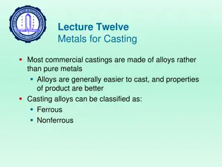
Classification of bulk forming
processes
Forging
Closed-die forging with flash
Closed-die forging w/o flash
Coining
Electro-upsetting
Forward extrusion forging
Backward extrusion forging
Hobbing
Isothermal forging
Nosing
Open-die forging
Rotary (orbital) forging
Precision forging
Metal powder forging
Radial forging
Upsetting
Incremental forging
Rolling
Sheet rolling
Shape rolling
Tube rolling
Ring rolling
Rotary tube piercing
Gear rolling
Roll forging
Cross rolling
Surface rolling
Shear forming
Tube reducing
Radial roll forming
Extrusion
Nonlubricated hot extrusion
Lubricated direct hot extr,
Hydrostatic extrusion
Co-extrusion
Equal channel angular extr.
Drawing
Drawing
Drawing with rolls
Ironing
Tube sinking
Co-drawing
Classification of sheet forming
processes
Bending and straight flanging
Brake bending
Roll bending
Surface contouring of sheet
Contour stretch forming (stretch forming)
Androforming
Age forming
Creep forming
Die-quench forming
Bulging
Vacuum forming
Linear contouring
Linear stretch forming (stretch forming)
Linear roll forming (roll forming)
Deep recessing and flanging
Spinning (and roller flanging)
Deep drawing
Rubber-pad forming
Marform process
Rubber-diaphragm hydroforming (fluid cell
forming or fluid forming)
Shallow recessing
Dimpling
Drop hammer forming
Electromagnetic forming
Explosive forming
Joggling
Useful Conditions for Metal
Additive Manufacturing
•
Single unique item or small number of
copies needed
•
Suitable materials and small in size (12” by
12” by 12”)
•
Shape is too complex to be generated in
any other way
Vision:
Advanced materials are essential to economic security and human
well-being and have applications in multiple industries, including those
aimed at addressing challenges in clean energy, national security, and
human welfare. To meet these challenges, the Materials Genome Initiative
will enable discovery, development, manufacturing, and deployment of
advanced materials at least
twice as fast as
possible today, at a fraction of
the cost.
Materials Genome Initiative
Materials Genome Initiative – Strategic Plan, 2014
Explore recent developments in the field of advanced materials and alloys, focusing on the need for new alloy development, high-throughput approaches, and key priority projects. Delve into the historical evolution of metallurgy, materials science, and engineering techniques for extreme environments, highlighting the innovations in nuclear alloys for quicker deployment.

Download Presentation

Please find below an Image/Link to download the presentation.
The content on the website is provided AS IS for your information and personal use only. It may not be sold, licensed, or shared on other websites without obtaining consent from the author.If you encounter any issues during the download, it is possible that the publisher has removed the file from their server.
You are allowed to download the files provided on this website for personal or commercial use, subject to the condition that they are used lawfully. All files are the property of their respective owners.
The content on the website is provided AS IS for your information and personal use only. It may not be sold, licensed, or shared on other websites without obtaining consent from the author.
E N D
Presentation Transcript
Towards more rapid deployment of alloys for nuclear Joseph W. Newkirk April 1, 2023
Outline > The need for Advanced Metals and Alloys > New alloy development > High-throughput development > Conclusions
Recent priority project calls 1. 2. 3. 4. 5. 6. 7. 8. 9. 10. Advanced materials Specific request Specific request Specific request Specific request Specific request Specific request Specific request Specific request Specific request
Recent priority project calls 1. 2. 3. 4. 5. 6. 7. 8. 9. 10. Advanced materials Specific request Specific request Specific request Specific request Specific request Specific request Specific request Specific request Specific request NASA DOE ARL AFOSR Etc.
Alchemy > For millennia metallurgy was an art Mix different ingredients and test Art was learned and passed down Often superior metallurgy was state secret > Until microscopes little understanding of science
Materials Science > Transition metals have large, nearly spherical electron shells > Lowest energy state is maximize nearest neighbors > Results in high densities of metals > Non-directional atomic bonding allows movement > Defects (dislocations) allow deformation without cracking at lowered strengths > Dislocations can lower strength of metal >100x
Materials Engineering > Stopping dislocations makes metal brittle > Hindering dislocation strengthens metal and retains some ductility > Metallurgists add 2nd phases to hinder dislocations > Removing phases allows fabrication > Restoring phases after fabrication locks strength into component
Materials for Extreme Environments > Higher temperatures > Harsher environments > Metal behavior at high temperature? What is high? ~50% of Tm, homologous Temp 193 27 590 549 1563
Materials for Extreme Environments > Higher temperatures > Harsher environments > Metal behavior at high temperature? What is high? 50% of Tm, homologous Temp > Now creep matters, not strength doesn t > Nickel alloys have high temperature use > Refractory metals highest 193 27 590 549 1563
Materials for Extreme Environments > Cost soars for hi T alloys > Compare Al to Co > Look at steel vs nickel > Later will mention Ta $170/lb
Materials for Extreme Environments > Cost includes several factors Material Fabrication Heat treatment Secondary treatments Market forces
Reactor steels Gillemot, F. Review on Steel Enhancement for Nuclear RPVs. Metals 2021, 11, 2008.
RPV structure > Low alloy steels form pressure vessel by forging > Inner surface clad with stainless steel by welding tefan, J. et al. Microstructure and Failure Processes of Reactor Pressure Vessel Austenitic Cladding. Metals 2021, 11, 1676.
Reactor steel degradation > Over time steel properties change > Increased hardness is usually accompanied by lower fracture toughness Ulbricht, A., et al. Effect of Neutron Flux on an Irradiation-Induced Microstructure and Hardening of Reactor Pressure Vessel Steels. Metals 2022, 12, 369
Irradiation damage process Fast neutrons and heavy ions produce cascade displacements Electron irradiations create single Frenkel defects (point defects of interstitials and vacancies) Low energy protons and light ions create similar defects as electrons Diffusion of transmutation products Helium & Hydrogen (embrittlement)
Advanced reactor concepts > High temperatures > High neutron fluences > Corrosive cooling fluids > High pressure Operating temperature = 300 1000 oC Neutron energy < 1 3 MeV Dose range = ~ 30 200dpa Time of operation 10s of years > Long lifetimes
Reactor pressure vessel alloy Normal development cycle 1. Conceive 2. Experimental testing 3. Irradiation testing* 4. Optimize 5. Transition to full scale production* 6. Certify Cycle is optimistically 20 years
Reactor pressure vessel alloy Normal development cycle 1. Conceive 2. Experimental testing 3. Irradiation testing* 4. Optimize 5. Transition to full scale production* 6. Certify Cycle is optimistically 20 years
Radiation resistant materials Have radiation stable microstructure with reasonable density of small defect clusters and/or precipitates contributing to hardening Enhanced point defect recombination = reducing large clustering and extended defects = reducing radiation induced changes and radiation effects Typical radiation resistant materials have a softer matrix with hard phases dispersed in them dispersion strengthening. Hard dispersoids strengthen material, reduce creep and are sinks for defects. Ductile matrix with significant amount of dispersed phases should be the TARGET !
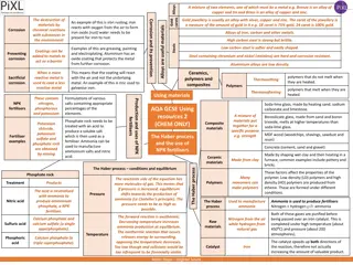
Ductility Strength High tempera ture embrittl ement Heat Inter-granular GB cavities & treatment & stress relief bubbles Size & distribution Grain structure Transmutatio irradiation If high Ductile Matrix n Comparatively in lower amounts Swelling & growth GB ; chemistry & pinning precipitates LONGER LIFE - SUCCESS Voids & Additive manufacturin g Radiatio n hardeni ng & embrittl ement Solidification structure Displacement Inclusions, voids & porosity irradiation cascade If low hard dispersed phase Dislocation climb, Micro segregation segregation evolution, network Creep & stress corrosio n Powder atomization Corrosion resistanc e Toughnes s PROCESS STRUCTURE PROPERTY RADIATION DAMAGE PROCESS
New material (classifications) Concept High entropy alloys already have high degree of disorder Many have good high temperature properties Attractive for possible RPV materials N. Birbilis, et al., npj Materials Degradation (2021) 5:14; https://doi.org/10.1038/s41529-021-00163-8
MPE strategy MPEs (Multi Principal Element alloys), when full solid solution are weak and unsuitable. Matrix ductile - contributes to the ductility of the alloy. Dispersed phase ductile/brittle - contributes to the strengthening of the alloy. Matrix & dispersed phase radiation and creep resistance Operating temperature range in advanced nuclear reactors 300 - 1000oC
PHASE DIAGRAM of B16 Fe 25.19 Cr 23.45 Mn 24.78 Co 26.58 (advanced reactor operation range) Liquidus temp -- 1345 oC Solidus temp -- 1289oC Delta T -- 56 oC Secondary Phases and (amount in mol) Temp ranges Major Phase BCC_B2#2 (0.21- 0.15)+ SIGMA#2 (0.05-.04) 200 - 320 oC SIGMA(0.73-0.8) BCC_B2#2 (0.15-0.1)+ SIGMA#2 (0.04 - 0) + HCP_A3 (0-0.06) 320 - 380 oC SIGMA(0.8-0.83) 380 - 500 oCSIGMA#2 (0.83 - BCC_B2#2 (0.1- 0) + HCP_A3 (0.06 - 0.1) 0.9) 500 - 570 oC SIGMA#2 (0.9) HCP_A3 (0.1) SIGMA#2 (0.9 - 0.89) HCP_A3 (0.1 - 0) + FCC_L12 (0 - 0.11) 570 - 610 oC 610 - 880 oCSIGMA#2 (0.89 - FCC_L12 (0.11 - 0.2) 0.8) 880 - 1180 oCSIGMA#2 (0.8-0.5)BCC_B2#2 (0-0.5) + FCC_L12 (0.2-0) 1180 - 1290 oC BCC_B2 (0.5-0.72) SIGMA (0.5-0.28) BCC_B2 (0.72- 0.27) SIGMA(0.28-0) + LIQ (0-0.73) 1290 - 1323 oC 1323 - 1341 oC LIQ (0.73-1) BCC_B2(0.27-0) High probability to form Lower probability to form Least probability to form ThermoCalc 2020a (TCHEA4 database)
D23 Ti14.60Zr27.82Mo29.26Nb28.33 RHEA Operational range
D23 microstructure Predicted: majority of softer BCC phase Smaller quantity of hard phase Should have cracking resistance Can be heat treated to disperse 2nd phase
High packing density for ATR SSJ design
Miniature tensile specimen (MT2) Material characterization Chemistry variation Spatial variation Process variation Benchmarking All dimensions are in mm DIC analysis
Smaller sample - higher packing density Enabling local property measurements Component level testing High temperature testing EDM shape prior to slicing Polished unbroken sample High throughput tester commercialized by PINE, LLC Top down view Side view J.W. Newkirk and J. Wang, Advances in Powder Metallurgy & Particulate Materials-2014, 11-16 11-22.
High-throughput tester PINE, LLC commissioned through small business grant Build and deliver tester Carousels for SSJ and MT2 Fully automated Radiation hardened
Conclusions New designs interact with new materials Development of new materials accelerated by: Computational modeling New verification methods More densely packed test reactor samples Development of new materials hampered by: Limitations of modeling Time for irradiation results Time for creep testing Time for environmental testing Regulations?
Experiment presented to INL 16 MPEs fabricated by arc melting compared to SPS Compositions studied using CALPHAD approach Experimental verification of models Compare to ideal microstructures Add capability in atomistic models Use CALPHAD to vary compositions
Radiation damage Absorbed at sinks leading to void formation, gas trapping & growth embrittlement & swelling Defects (voids, gas filled bubbles, dislocation loops, secondary phase precipitates) act as obstacles to dislocation motion (glide) Radiation- induced hardening Most Frenkel pairs (vacancy & interstitial) recombine during cascade annealing. Vacancies Those which do not, either stay isolated or diffuse to form clusters forming visible extended defects When material is stressed, dislocation climb occurs irradiation creep Movement of dislocations determine plasticity In-Cascade clustering (Dislocation loops and networks) Absorbed at sinks which gets enriched/ depleted in certain elements leading to solute segregation and eventually precipitation Cause 2nd phase formation (impurities) Precipitation of new phases with different microstructure than that of matrix Interstitials
COMPUTATIONAL MODELS & METHODS contd Amount and diffusion of defects or impurities are calculated from atom jump simulations (segregation & precipitation) Defect-dislocation, defect- dislocation loop interactions can be calculated; mechanical properties of materials Inputs are defects and defect jump rates simulated by MD or BCA Defect formation and migration energies can be calculated; hence properties of defects. Electronic structure features and ground state properties. Obtained from electronic densities calculated. Properties of point defects Defect transport & clustering DFT KMC (Density Function Theory) (Kinetic Monte Carlo) DDD RE/RT Forces on each dislocation is determined taking into account all possible interactions Done by calculating elastic strain energy prolonged irradiation, damage by dislocations final mechanical property (Discreet Dislocation Dynamics) (Rate Models microstructure evolution especially swelling Gives the average defect concentration Spans from defect production in cascade to changes in macroscopic properties Inputs are MD data Equations or Rate theory) Motion of dislocations Defect densities & microstructure
Classification of bulk forming processes Forging Closed-die forging with flash Closed-die forging w/o flash Coining Electro-upsetting Forward extrusion forging Backward extrusion forging Hobbing Isothermal forging Nosing Open-die forging Rotary (orbital) forging Precision forging Metal powder forging Radial forging Upsetting Incremental forging Rolling Sheet rolling Shape rolling Tube rolling Ring rolling Rotary tube piercing Gear rolling Roll forging Cross rolling Surface rolling Shear forming Tube reducing Radial roll forming Extrusion Nonlubricated hot extrusion Lubricated direct hot extr, Hydrostatic extrusion Co-extrusion Equal channel angular extr. Drawing Drawing Drawing with rolls Ironing Tube sinking Co-drawing
Classification of sheet forming processes Bending and straight flanging Brake bending Roll bending Surface contouring of sheet Contour stretch forming (stretch forming) Androforming Age forming Creep forming Die-quench forming Bulging Vacuum forming Linear contouring Linear stretch forming (stretch forming) Linear roll forming (roll forming) Deep recessing and flanging Spinning (and roller flanging) Deep drawing Rubber-pad forming Marform process Rubber-diaphragm hydroforming (fluid cell forming or fluid forming) Shallow recessing Dimpling Drop hammer forming Electromagnetic forming Explosive forming Joggling
Useful Conditions for Metal Additive Manufacturing Single unique item or small number of copies needed Suitable materials and small in size (12 by 12 by 12 ) Shape is too complex to be generated in any other way
Materials Genome Initiative Vision: Advanced materials are essential to economic security and human well-being and have applications in multiple industries, including those aimed at addressing challenges in clean energy, national security, and human welfare. To meet these challenges, the Materials Genome Initiative will enable discovery, development, manufacturing, and deployment of advanced materials at least twice as fast as possible today, at a fraction of the cost. Materials Genome Initiative Strategic Plan, 2014


")


")