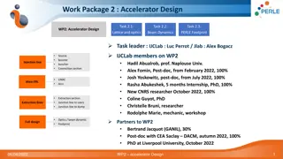
Overview of PERLE Injector Design & ALICE Electron Gun Re-optimisation
The PERLE injector, part of the Powerful Energy Recovery Linac for Experiments (PERLE), operates at 7 MeV injection energy with a bunch charge of 500 pC and a bunch repetition rate of 40.1 MHz. The layout includes a DC photoemission electron gun, bunching and focusing sections, and a superconducting booster linac. Re-optimisation of the ALICE electron gun was undertaken to accommodate the higher bunch charge of PERLE. The procedure involved optimizing electrode geometry, laser parameters, and solenoid settings to achieve specific objectives while ensuring operational effectiveness at both 220 kV and 350 kV voltages.

Download Presentation

Please find below an Image/Link to download the presentation.
The content on the website is provided AS IS for your information and personal use only. It may not be sold, licensed, or shared on other websites without obtaining consent from the author. Download presentation by click this link. If you encounter any issues during the download, it is possible that the publisher has removed the file from their server.
E N D
Presentation Transcript
PERLE injector design review 16/12/20 Ben Hounsell
Overview PERLE injector specification and design considerations ALICE electron gun re-optimisation Injector optimisation (Cathode to booster exit) Merger optimisation
PERLE (Powerful Energy Recovery Linac for Experiments) A 3 turn, 500 MeV, 20 mA beam current ERL. Has a number of applications including as a test facility for the LHeC. Its role as a test facility for the LHeC is the origin of several of the requirements in the specification. Uses the same 802 MHz SRF cavities as the LHeC. Planned to be located at IJCLab in Orsay.
PERLE injector specification PERLE Parameters Injection energy 7 MeV Bunch charge 500 pC Bunch repetition rate 40.1 MHz Average current 20 mA RMS bunch length 3 mm Emittance < 6 mm mrad Uncorrelated energy spread < 10 keV
PERLE injector layout The PERLE injector consists of: 350 kV DC photoemission electron gun. Using an alkali antimonide photocathode for unpolarised operation. A bunching and focusing section consisting of a solenoid, a normal conducting buncher cavity and then another solenoid. A superconducting booster linac with 802 MHz cavities with individual control of the amplitudes and phases. Merger to transport the beam into the main ERL.
ALICE electron gun re- optimisation
Re-optimisation of the ALICE electron gun Further work was done to re- optimise the ALICE electron gun. This is necessary for two reasons: PERLE operates with a much higher bunch charge of 500 pC compared to the 80 pC of ALICE. For polarised operation the gun needs to be operated at a lower voltage, 220 kV, so the gun should be effective at both 220 kV and 350 kV. Finding a compromise solution between 350 kV and 220 kV operation was the main goal of the additional work here. An image of the ALICE ERL gun
Re-optimisation procedure The electron gun electrode geometry, laser parameters and first solenoid were optimised together. The optimisation had four objectives. To minimise the average slice emittance and rms beamsize for both voltages 220 kV and 350 kV. The optimisation had four constraints to keep the electrode surface electric field below 10 MV/m (to prevent field emission) and to have no particle losses. These two objectives applied for both voltages. The electron gun electrostatics were simulated with POISSON and the beam dynamics with ASTRA. The optimisation was performed with the many objective optimisation algorithm NSGAIII.
Geometry parameterisation The cathode and the anode electrodes geometry could both be varied. The cathode consisted of a flat focusing section and then a curved section modelled as a Bezier curve. It was described by 5 variables. The anode consisted of two straight sections with an angle between them and was described by 2 variables.
Selected electron gun The selected electron gun has a much low focusing angle than the 20 degree angle of the original design. The anode has been moved slightly in. These changes increase the cathode surface electrode field.
Injector cathode to booster exit optimisation
Injector optimisation The new gun design was then used as part of an optimisation of the injector up until the booster exit The optimisation had 5 objectives to minimise at the booster exit: Transverse emittance Longitudinal emittance RMS energy spread X halo parameter Z halo parameter Constraints were used to keep the beam size below 6 mm as well as to achieve a final beam energy of 7 MeV and a final bunch length of 3 mm. The optimisation was performed using NSGAIII. 13
Transverse phase space evolution px x (m)
Longitudinal phase space evolution pz z (m)
Intrabunch particle motion x (m) x (m) z (m) z (m)
Ultimate parameters of the current injector design The unpolarised PERLE injector is capable of meeting the required specification at the booster exit. The transverse emittance and phase space are satisfactory. The Longitudinal phase space is less linear than would be desired. The possibility of linearization will be investigated. Achieved bunch parameters Transverse emittance/ mm mrad 4.0 Longitudinal emittance/ keV mm 25.1 Bunch length/ mm 3.0 Energy/ MeV 7.0 21
Merger scheme selection and optimisation
ERL mergers Once the beam has been accelerated up to the injection energy it needs to be merged into the main ERL loop. The merger is the beamline which does this. This must be done in a way that allows the higher energy beams that have already recirculated one or more times to continue to circulate. The high repetition rate of ERLs means that this is done with fixed magnetic elements rather than kickers. One dipole is common to both the injected beam and the recirculated beam. Before this dipole is the re- injection chicane so that the common dipole bends the recirculated beams back on axis through the main linac. Booster linac Main linac Recirculated beam Booster linac merger Main linac Re-injection chicane Common dipole
A some design philosophies PERLE is a test facility and consequently will need more flexibility than a facility built for a specific purpose and mode of operation. Use adjustable elements where ever possible. This is to try and keep as much flexibility in operation as possible and to avoid building an assumption about the amount of space charge force present into the physical system. As it may be desirable to operated with different bunch charges, different bunch sizes, different injection momentums. Avoid having matching quadrupoles in the main loop between the merger and the main linac. These quadrupoles would be seen by the recirculating beams which may pose a problem. In addition the current PERLE lattice doesn t have a lot of space between the merger and main linac.
3 possible sources of emittance growth Transverse space charge effects: This is the standard projected emittance growth mechanism seen earlier in the injector. Ideal solution: Emittance compensation, not trivial in non-axisymmetric beamlines, needs laminar flow (no crossovers, so no strong focusing) Mitigation: Compensate through the booster prior to the bending section and keep the merger as short as possible to limit the time for emittance growth. Longitudinal Space Charge effects: The longitudinal space charge changes the energy of the particles and changes how the dispersion behaves leaving some residual dispersive emittance growth. Ideal solution: Meet the decoupling conditions (zig-zag or similar) Mitigation: Keep the bending angles in the dispersive section as small as possible and keep it as short as possible. This requires accepting that there will be some residual dispersion. CSR (Coherent Synchrotron Radiation): This also changes the energy of the particles in the bending magnets and consequently has an effect on the cancellation of the dispersion.
Motivation for four dipole schemes The purpose of the four dipole schemes is to mitigate the effects of the energy change of the particles, due to longitudinal space charge, on the dispersion. In the paper on the zig-zag merger four conditions for achromaticity in the presence of a generalised dispersion are given. Mergers with bilateral symmetry meet two of these conditions automatically. The zig-zag meets the other two by its geometry. The four dipole schemes presented here attempt to meet the last two conditions by simply having enough free parameters in the focusing elements.
Merger optimisation Four merger schemes were optimised so that they could be compared. The optimisation had 2 objectives: Minimise transverse emittance at the entrance to the main linac. Minimise twiss mismatch at the entrance to the main linac. Defined as: ??? ??, ?????? ??, ?????? The optimisation was done using NSGAII The variables were different for the different optimisations but included things such as magnet positions, dipole bend angles, focusing magnet settings and input twiss parameters. ???(??, ???????? ?? ?????? ) ???(??,???????? ??, ?????? ) ??, ?????? ???(??, ???????? ??, ?????? ) ???(??, ???????? ??, ?????? ) ??, ?????? , , ,
RMS beam sizes z (m) x (m)
RMS transverse emittance px x (m)
RMS longitudinal phase space pz z (m)
Current status and general plans There is currently a functional gun optimisation as well as the tools to redo that optimisation if it becomes neccesary. A 5 cavity injector optimisation exists and meets the requirements. A possible change to a 4 cavity cryomodule would mean that a new optimisation will be needed. The tools for doing that re-optimisation are in place. A merger solution does exist although further work is needed. The CSR and phase slippage should be investigated. Either the implications of the current optimisation on the beam dynamics in the main lattice should be investigated or possibly modifying some of the requirements on the merger which might open up alternative schemes.
Injector charge distribution evolution x (m) z (m)
Injector charge distribution slices evolution x (m) z (m)
Injector charge distribution evolution x (m) z (m)
4 dipole merger charge distribution evolution x (m) z (m)
4 dipole merger x transverse phase space evolution px x (m)
4 dipole merger longitudinal phase space evolution pz z (m)
3 dipoles with 6 quads 3 dipoles with 6 quads
4 dipole staircase 4 dipole Staircase
Dogleg 3 quads Dogleg with 3 quads
U-bend 1 quad Ubend with 1 quad


 halo parameter evolution")