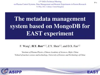
Coherent Electron Cooling Experiment at RHIC - Project Overview and Experimental Possibilities
Coherent electron cooling experiment at RHIC is led by Vladimir N. Litvinenko with Jean Clifford Brutus as the project manager. The CeC group, consisting of researchers from Brookhaven National Laboratory and Stony Brook University, aims to test various experimental scenarios, including high gain FEL amplifiers, dispersion sections for hadrons, and plasma cascade microbunching amplifiers. The need for strong hadron cooling is highlighted to address challenges in achieving high beam polarization and luminosity for both electron and ion beams in the collider. The project involves testing different technologies and modifications to the RHIC lattice to improve beam performance.

Download Presentation

Please find below an Image/Link to download the presentation.
The content on the website is provided AS IS for your information and personal use only. It may not be sold, licensed, or shared on other websites without obtaining consent from the author. Download presentation by click this link. If you encounter any issues during the download, it is possible that the publisher has removed the file from their server.
E N D
Presentation Transcript
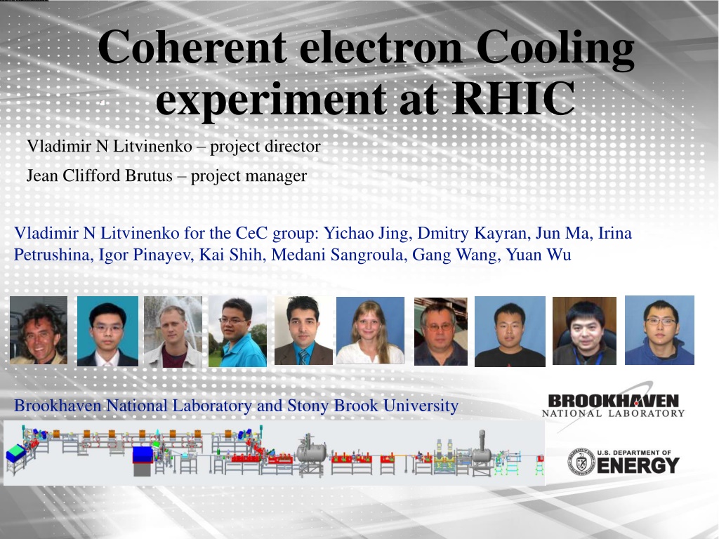
Coherent electron Cooling experiment at RHIC Vladimir N Litvinenko project director Jean Clifford Brutus project manager Vladimir N Litvinenko for the CeC group: Yichao Jing, Dmitry Kayran, Jun Ma, Irina Petrushina, Igor Pinayev, Kai Shih, Medani Sangroula, Gang Wang, Yuan Wu Brookhaven National Laboratory and Stony Brook University
Coherent electron Cooling All CeC systems are based on the identical principles: Hadrons create density modulation in co-propagating electron beam Density modulation is amplified using broad-band (microbunching) instability Time-of-flight dependence on the hadron s energy results in energy correction and in the longitudinal cooling. Transverse cooling is enforced by coupling to longitudinal degrees of freedom. CeC central section Hadrons E < E0 vh Modulator Electron-beam density amplifier and time-of-flight dispersion section for hadrons Electrons Kicker E0 2 RDt E > E0 Ez 2 RD// e= h
What can be tested experimentally? Litvinenko, Derbenev, PRL 2008 RHIC Run 18 High gain FEL amplifier with low-aw wigglers Ratner, PRL 2013 Dispersion section ( for hadrons) Eh Cooling test would require significant modification of the RHIC lattice & superconducting magnets quadrupling the cost Kicker Hadrons Modulator I E > Eh Micro-bunching Amplifier -R56/4 -R56/4 -R56/4 R56 Modulator 2 Modulator 5 Electrons Litvinenko, Wang, Kayran, Jing, Ma, 2017 RHIC Runs 20-22 Plasma Cascade microbunching Amplifier Kicker Modulator Hadrons Plasma-Cascade Amplifier Electrons Litvinenko, Cool 2013 E < Eh Cooling test would require significant modification of the RHIC lattice & superconducting magnets quadrupling the cost Dispersion section ( for hadrons) Eh Kicker Hadrons Modulator E > Eh Laser Amplifier R56 Radiator Energy modulator Electrons Derbenev is suggesting to explore CSR as and CeC amplifier 4
Why strong hadron cooling is needed? National Academy of Sciences Assessment of U.S.-Based Electron- Ion Collider Science: The accelerator challenges are two fold: a high degree of polarization for both beams, and high luminosity.
Why we need the CeC experiment? Quote from the pCDR review committee report: The major risk factors are strong hadron cooling of the hadron beams to achieve high luminosity, and the preservation of electron polarization in the electron storage ring. The Strong Hadron cooling [Coherent Electron Cooling (CeC)] is needed to reach 1034/(cm2s) luminosity. Although the CeC has been demonstrated in simulations, the approved proof of principle experiment should have a highest priority for RHIC. 2013-2018 2019-present
CeC experiment at RHIC 2014-2017: built cryogenic system, SRF accelerator and FEL for CeC experiment 2018: started experiment with the FEL-based CeC. It was not completed: 28 mm aperture of the helical wigglers was insufficient for RHIC with 3.85 GeV/u Au ion beams We discovered microbunching Plasma Cascade Instability - new type of instability in linear accelerators. Developed design of Plasma Cascade Amplifier (PCA) for CeC In 2019-2020 nPCA-based CeC with seven solenoids and vacuum pipe with 75 mm aperture was built and commissioned. During Run 20, we demonstrated high gain Plasma Cascade Amplifier (PCA) and observed presence of ion imprint in the electron beam New time-resolved diagnostics beamline was built last year and commissioned during this rung. Now we focusing on demonstrating longitudinal cooling. High gain 10 THz FEL (2018) RHIC ion beam CeC SRF accelerator Unchanged 4-cell PCA Kicker Modulator RHIC ion beam The CeC Plasma Cascade Amplifier has bandwidth of 15 THz >2,000x of the RHIC stochastic cooler 7
Run 21: Major disruption of the project We lost 7 weeks of operation during this run because of the damage to our SRF gun The UHV cathode transport and positioning system was severely damaged and it was not result of operations performed by the CeC engineers, technicians and scientist. C-AD completed the investigation and filed report to DOE. It resulted is burn-off of cathode mount and severe contamination of the SRF gun and the cathode transfer system It took enormous efforts to restore the SRF gun operation The cathode transfer system had to be fully disassembled and rebuilt The SRF gun went through an elaborate, labor-intensive and previously untested procedures to it clean-up and to burn-off debris Luckily, we were able to restore and even improve the SRF gun cavity performance Poor quality of the photocathodes remains the problem, which we hope to overcome by mid-June As the result of this damage, we lost 7 week of operations, which we are still trying to catch up with. 8
Time-resolve diagnostics beam-line Fully Commissioned V Run 21 main addition is the time-resolved diagnostics beam-line To evaluate local beam quality of electron beam with time resolution of 1 psec Played critical role for achieving Key Performance Parameter for this run 9
KPPs Electron beam KPP Parameter Lorentz factor Repetition frequency, kHz Electron beam full energy, MeV Total charge per bunch, nC Average beam current, A Ratio of the noise power in the electron beam to the Poison noise limit RMS momentum spread p = p/p, rms Normalized rms slice emittance, m rad Planned 28.5 78.2 14.56 1.5 117 <100 Demonstrated up to 29 78.2 up to 14.8 nominal 1.5, up to 20 120 <10 (lattice of Run20)* v v v v v *** v v 1.5 10-3 5 <5 10-4, slice 2 10-4 2.5 *** In order to save preparation time and to catch-up with the plans after significant time lost caused by the damage to the SRF gun, we do not repeat lengthy measurements of the beam noise, which were performed during Run 19 and Run 20. Instead, we are repeating the setting used to achieve necessary low noise level in the beam. Noise measurement will be performed parasitically during our attempt to demonstrate CeC cooling. 10
Beam peak current and energy spread Time 4.2 10-4 FWHM 1.8 10-4 RMS Energy Peak current of 52 A Direct pass 30-degree energy spectrometer 11
Beam emittance Quadrupole scan in the triplet section: Measured normalized emittances are 3.5 m for horizontal and 3.4 m vertical Time resolved horizontal slice beam emittance with normalized emittances of the beam core bellow 2 m 12
Beam-Based Alignment for CeC solenoids Accurate alignment of the electron beam trajectory is critically important for operation of the PCA-based CeC. This year we completed this process First, we aligned ion beam with centers of two quadrupoles in the CeC section Second, we accurately measured both location and the angle of the solenoid s axes using ion beam and RHIC BPM this is novel method that wee developed. Solenoids then were aligned with best accuracy the survey group can provide Third, during last month after a number of set-backs, we aligned electron beam with axes of solenoids This in new techniques we developed to guarantee overlapping of electron and ion beams ATF QUAD ATF QUAD Solenoid 3 Solenoid 2 Solenoid 7 Solenoid 1 Solenoid 6 Solenoid 5 Solenoid 4 BPM kick1 BPM amp2 BPM mod1 BPM kick2 BPM amp1 BPM amp3 Profile monitor BPM mod2 HV trim 11 HV trim 10 HV trim 6 HV trim 2 HV trim 9 HV trim 8 HV trim 1 HV trim 12 HV trim 7 HV trim 5 H trim HV trim 4 H trim HV trim 3 13
Beam energy measurement in the CeC Novel method of absolute beam energy measurement based on Ampere law and knowing number of current and number of turns in solenoid: Current accuracy ~ 0.2%. Main source of errors is in the orbit jitter.
Restoring high-gain PCA Run 20 Run 21, May 23, 2021 Scope Scope Lock-in amplifier Lock-in amplifier
REPORTABLE MILESTONES Milestone ID Reportable milestone Date C v 1 2 3 4 5 6 7 8 9 10 11 Experiment start FY20Q1 FY21Q4 FY21Q4 FY22Q1 FY22Q1 FY22Q3 FY22Q4 FY23Q3 FY23Q4 FY23Q4 FY23Q4 Necessary Beam Parameters (KPP) established for Run 20 Investigation of plasma cascade amplifier complete Investigation of the ion imprint in the electron beam complete Receive Approval for CeC TRDBL commissioning Necessary Beam Parameters (KPP) established for Run 21 Investigation of the CeC longitudinal cooling complete Necessary Beam Parameters (KPP) established for Run 22 Investigation of the 3D CeC Cooling complete Final report to DOE NP Experiment Complete v v v v v 16
Summary Plasma-cascade amplifier operation is restored. We are making steady even slower that we would like progress towards testing CeC with ion beam June will be critical month for the CeC demonstration. We are requesting 3 to 5 days of additional dedicated time for CeC experiments. Our request will be discussed at next RHIC planning meeting (June 8) CeC team is very busy with the experiment, but when we have time we use it to work on cost-effective design of CeC for EIC 17
EIC CeC with PCA 3-path 150 MeV ERL Solenoids Periodic 4-cell PCA SRF gun Kicker 0.78 T 10 m 0.32 T 2 m Modulator 30 m Name Current experiment Periodic, 4 cells, regular 28.5 Au ions 26.5 14.56 2x1 0.2 1.5 75 5 10-6 25 100 regular 15-20 CeC cooler for EIC Periodic, 4 cells, optimized 293 Protons 275 150 2x15 0.15 1.5 150 5 10-6 500 400 1:2 <5 PCA Lattice Hadrons Eh, GeV Ee, MeV l, m a0, mm Q, nC I0, A norm, m Frequency, THz PCA gain Lattice 3D emittance Cooling time, min 12