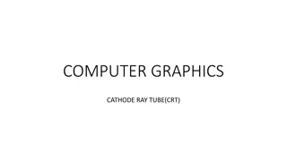
Evolution of Cathode Ray Tube (CRT) Displays: Historical Milestones
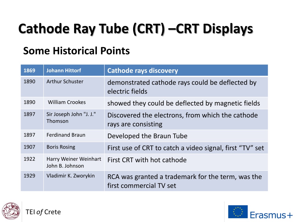
The historical evolution of Cathode Ray Tube (CRT) displays is highlighted, starting from the discovery of cathode rays in 1869 by Johann Hittorf to the development of the first commercial TV set by RCA in 1929. Key milestones include the demonstration of electron deflection by electric and magnetic fields and the introduction of the Braun Tube. CRT is a vacuum tube with an electron gun used for displaying images on a fluorescent screen, commonly used in televisions, computer monitors, and oscilloscopes.

Download Presentation

Please find below an Image/Link to download the presentation.
The content on the website is provided AS IS for your information and personal use only. It may not be sold, licensed, or shared on other websites without obtaining consent from the author. Download presentation by click this link. If you encounter any issues during the download, it is possible that the publisher has removed the file from their server.
E N D
Presentation Transcript
Cathode Ray Tube (CRT) CRT Displays Some Historical Points Cathode rays discovery 1869 Johann Hittorf 1890 Arthur Schuster demonstrated cathode rays could be deflected by electric fields 1890 William Crookes showed they could be deflected by magnetic fields 1897 Sir Joseph John "J. J." Thomson Discovered the electrons, from which the cathode rays are consisting 1897 Ferdinand Braun Developed the Braun Tube 1907 Boris Rosing First use of CRT to catch a video signal, first TV set 1922 Harry Weiner Weinhart John B. Johnson First CRT with hot cathode 1929 Vladimir K. Zworykin RCA was granted a trademark for the term, was the first commercial TV set
"Crookes tube2 diagram" by created by Chetvorno, rebuilt by Drondent - own work by Chetvorno and rebuilt by Drondent
"Braun cathode ray tube" by Eugen Nesper - Retrieved on 11 October 2013 from Eugen Nesper 1921 Handbuch der Drahtlosen Telegraphie und Telephonie, Julius Springer, Berlin, p. 78, fig. 46 on Google Books. Licensed under Public Domain via Commons -
"Egun" by Roychai at English Wikipedia - Transferred from en.wikipedia to Commons.. Licensed under Public Domain via Commons -
http://www.circuitstoday.com/wp-content/uploads/2009/09/CRT-Cathode-Ray-Tube.jpghttp://www.circuitstoday.com/wp-content/uploads/2009/09/CRT-Cathode-Ray-Tube.jpg
Description CRT is a vacuum tube containing an electron gun and a fluorescent screen used to view images. http://www.circuitstoday.com/wp-content/uploads/2009/09/CRT-Cathode-Ray-Tube.jpg It has a means to accelerate and deflect the electron beam(s) onto the fluorescent screen to create the images. The image may represent electrical waveforms (oscilloscope), pictures (television, computer monitor), radar targets and others.
https://www.youtube.com/watch?v=IIrNJHMyzeI https://www.youtube.com/watch?v=Fal_QtW0MW4 https://www.youtube.com/watch?v=Od7zrA5w3N8 https://www.youtube.com/watch?v=r38nVmxBfvM
Fluorescent Screen of CRT The light produced by the screen of a CRT is due to the electrons that strike the phosphor of the screen. The luminescence due to electron bombardment is called cathodoluminescence. CL does not disappear immediately when bombardment by electron ceases, i.e., when the signal becomes zero. The time period for which the trace remains on the screen after the signal becomes zero is known as persistence. The persistence may be as short as a few microseconds, or as long as tens of seconds or even minutes.
Fluorescent Screen of CRT Medium persistence traces are mostly used for general purpose applications. Long persistence traces are used in the study of transients. Long persistence helps in the study of transients since the trace is still seen on the screen after the transient has disappeared. Short persistence is needed for extremely high-speed phenomena.
Fluorescent Screen of CRT The kinetic energy of the electron beam is converted into both light and heat energy when it hits the screen. The heat so produced gives rise in phosphor burn which is damaging and sometimes destructive. This degrades the light output of phosphor and sometimes may cause complete phosphor destruction. Thus the phosphor must have high burn resistance to avoid accidental damage.
Fluorescent Screen of CRT Common phosphors used for CRT screens are shown in the next table. Commercial phosphors for CRTs are named using the letter P following by a number
Standard phosphor types Wavelen gth Peak width Phosphor Composition Colour Persistence Usage Notes Oscilloscopes and monochrom e monitors CRT, Lamp P1, GJ Zn2SiO4:Mn Green 528 nm 40 nm 1-100ms P2 ZnS:Cu(Ag)(B*) Blue-Green 543 nm Long CRT Oscilloscopes Amber monochr ome monitors P3 Zn8:BeSi5O19:Mn Yellow 602 nm Medium/13ms CRT Black and white TV CRTs and display tubes. 565,540 nm P4 ZnS:Ag+(Zn,Cd)S:Ag White Short CRT Black and white TV CRTs and display tubes, Cd free. ZnS:Ag+ZnS:Cu+Y2O 2S:Eu P4 (Cd-free) White Short CRT
Fluorescent Screen of CRT Similarly the phosphor screen is provided with an aluminum layer called aluminizing of the cathode ray tube. This is shown in image below. The aluminium layer must be thick enough to reflect light efficiently, yet not so thick as to absorb too great a proportion of the electron beam that excites the phosphor.
The Aluminizing layers serve three functions: To avoid buildup of charges on the phosphor which tend to slow down the electrons and limits the brightness. It serves as a light scatter. When the beam strikes the phosphor with aluminized layer, the light emitted back into the tube is reflected back towards the viewer which increases the brightness. The aluminum layer acts as a heat sink for the phosphor and thus reduces the chances of the phosphor burning.
Phosphor screen characteristics Many phosphor materials having different excitation times and colors as well as different phosphorescence times are available. The type P1, P2, P11 or P31 are the short persistence phosphors and are used for the general-purpose oscilloscopes. Medical oscilloscopes require longer phosphor decay and hence phosphors like P7 and P39 are preferred for such applications Very slow displays like radar require long persistence phosphor to maintain sufficient flicker free picture. Such phosphors are P19, P26 and P33. The phosphors P19, P26, P33 have low burn resistance. The phosphors P1, P2, P4, P7, P11 have medium burn resistance while P15,P31 have high burn resistance.
Phosphor Composition Colour Wavelength Peak width Persistence Usage Notes ZnS:Cu or ZnS:Cu,Ag Yellowish- green P31, GH 0.01-1 ms CRT Oscilloscopes
Why P31 is commonly used? Out of these varieties, the materials P31 is used commonly for general purpose oscilloscopes due to following characteristics: It gives color to which human eye response is maximum. It gives short persistence required to avoid multiple image display. It has high burn resistance to avoid the accidental damage. Its illumination level is high. It provides high writing speed. Note: the light output of a fluorescent screen is proportional to the number of bombarding electrons, i.e., to the beam current.
https://www.youtube.com/watch?v=GzMh4q-2HjM https://www.youtube.com/watch?v=5NwMPcYH71g https://www.youtube.com/watch?v=dlT-seESkj0
Spectra of constituent blue, green and red phosphors in a common cathode ray tube.
CRTs continue to be in use in the printing and broadcasting industries as well as in the professional video, photography, and graphics fields due to their greater color fidelity, contrast, and better viewing from off-axis (wider viewing angle). CRT monitors are still used in the study of the brain's visual processing (e.g. in psychophysics). The speed and fidelity of their response, makes them well-suited for experiments where scientists need to have very fine control over stimuli which are presented to an observer.
Although a mainstay of display technology for decades, CRT- based computer monitors and televisions constitute a dead technology. The demand for CRT screens has dropped precipitously since 2000, and this falloff had accelerated in the latter half of that decade. Sony Corp. ended production of cathode-ray tubes in Japan in 2004, but continued to produce the old-style TVs under the "Trinitron" brand at plants in Singapore and Malaysia to meet limited demand in Latin America and parts of Asia. In 2008 has decided to pull the plug on the remaining operations.
Advantages High contrast ratio (over 15,000:1),excellent color, fairly wide color gamut and low black level. No native resolution; the only current display technology capable of true multisyncing (displaying many different resolutions and refresh rates without the need for scaling). No input lag. No ghosting and smearing artifacts during fast motion due to sub-millisecond response time, and impulse-based operation. Near zero color saturation, contrast or brightness distortion. Excellent viewing angle. Allows the use of light guns/pens. Can be used or stored in both extreme hot and cold temperature conditions without harm to the system.
Disadvantages Large size and weight, especially for bigger screens (a 20-inch (51 cm) unit weighs about 25 kg). Geometric distortion caused by variable beam travel distances. High power consumption. On average, a CRT monitor consumes 2 10 the power that an identically sized LCD monitor would consume, depending on the type of backlight used in the LCD screen, and its brightness setting. A lot of heat can be emitted during operation due to relatively high power consumption, which can mean a short product lifespan. Can suffer screen burn-in, though not as quickly as Plasma displays.
Disadvantages Produces noticeable flicker at refresh rates lower than 85 Hz. Hazardous to repair/service without proper training and precautions taken. Maximum size for direct-view displays is limited to about 40 inches due to practical and manufacturing restrictions (a CRT display of this size can weigh about 150 kg), though the sizing can be increased with an array of separate displays, such as the original Jumbotron used at sports arenas. The glass envelopes contains toxic lead and barium as X- ray radiation shielding. The phosphors can also contain toxic elements such as cadmium. Many countries treat CRTs as toxic waste and prohibit their disposal in landfills or by incineration.
Disadvantages Purity and convergence in color tubes, affected by the Earth's magnetic field, usually roughly factory preset (biased) for operation in either the northern hemisphere, the southern hemisphere, or the equatorial area, but may require trimming at final location. Adjustment at final location requires a high degree of technical skill, as well as safety precautions associated with opening the display housing. Sensitive to magnetic interference, which can cause the image to shimmer (e.g. if a transformer or other electro-magnetic source is too close to the screen) or the colors to shift (e.g. if an unshielded speaker is too close to the screen).
Disadvantages Image edges are slightly diffuse (blurred), compared to the razor sharp stationary image an LCD, PDP, or other screen with fixed predefined pixels can produce. For text displays, computer-generated diagrams and line drawing, and other images composed mostly of sharp edges, razor sharp pixel definition is often preferred. However, this may be seen as an advantage for continuous-tone images such as photographic television, as it yields more natural images with no pixellation and it introduces a natural anti-aliasing effect to image information that is pixelated by its origin. A halo may appear around bright objects on a mostly dark screen. They have been phased out in favor of plasmas, LCDs and OLEDs.
TV Pixels and Our Brain If you divide a still image into a collection of small colored dots, your brain will reassemble the dots into a meaningful image. This is no small feat, as any researcher who has tried to program a computer to understand images will tell you. The only way we can see that this is actually happening is to blow the dots up so big that our brains can no longer assemble them, like this:
Most people, sitting right up close to their computer screens, cannot tell what this is a picture of -- the dots are too big for your brain to handle. By standing at a distance, the dots become small enough for the brain to integrate them into a recognizable image. Both televisions and computer screens (as well as newspaper and magazine photos) rely on this fusion-of-small-colored-dots capability in the human brain to chop pictures up into thousands of individual elements. On a TV or computer screen, the dots are called pixels. The resolution of your computer's screen might be 800x600 pixels, or maybe 1024x768 pixels. What are the best resolution achieved today for TV ?
TV Motion and Our Brain If you divide a moving scene into a sequence of still pictures and show the still images in rapid succession, the brain will reassemble the still images into a single, moving scene. Take, for example, Sallie Gardner at a Gallop that is a series of photographs consisting of a galloping horse, the result of a photographic experiment by Eadweard Muybridge on June 15, 1878
The Black-and-White TV Signal In a black-and-white TV, the screen is coated with white phosphor and the electron beam "paints" an image onto the screen by moving the electron beam across the phosphor a line at a time. To "paint" the entire screen, electronic circuits inside the TV use the magnetic coils to move the electron beam in a "raster scan" pattern across and down the screen. The beam paints one line across the screen from left to right. It then quickly flies back to the left side, moves down slightly and paints another horizontal line, and so on down the screen.
In this figure, the blue lines represent lines that the electron beam is "painting" on the screen from left to right, while the red dashed lines represent the beam flying back to the left. When the beam reaches the right side of the bottom line, it has to move back to the upper left corner of the screen, as represented by the green line in the figure. When the beam is "painting," it is on, and when it is flying back, it is off so that it does not leave a trail on the screen. The term horizontal retrace is used to refer to the beam moving back to the left at the end of each line, while the term vertical retrace refers to its movement from bottom to top.
As the beam paints each line from left to right, the intensity of the beam is changed to create different shades of black, gray and white across the screen. Because the lines are spaced very closely together, your brain integrates them into a single image. A TV screen normally has about 480 lines visible from top to bottom. Standard TVs use an interlacing technique when painting the screen. In this technique, the screen is painted 60 times per second but only half of the lines are painted per frame. The beam paints every other line as it moves down the screen -- for example, every odd-numbered line. Then, the next time it moves down the screen it paints the even-numbered lines, alternating back and forth between even- numbered and odd-numbered lines on each pass. The entire screen, in two passes, is painted 30 times every second. The alternative to interlacing is called progressive scanning, which paints every line on the screen 60 times per second. Most computer monitors use progressive scanning because it significantly reduces flicker
Because the electron beam is painting all 525 lines 30 times per second, it paints a total of 15,750 lines per second. (Some people can actually hear this frequency as a very high-pitched sound emitted when the television is on.) While the beam of electrons is sweeping across the Phosphor on the inside of the screen the number of electrons in the beam can be changed so that the brightness of the light coming from the screen changes along with the number of electrons. So as the electron beam is swept across the inside of the CRT's screen the number of electrons in the beam keeps changing and as this happens the brightness of the point on the screen that the electron beam is striking changes along with it. This means that all the points on the screen can each have a different brightness level. So that when you see all these points together on the screen they form a television picture made up of black, white and gray areas.
When a television station wants to broadcast a signal to your TV, or when your VCR, DVD, Memory Stick , wants to display the movie on your TV, the signal needs to mesh with the electronics controlling the beam so that the TV can accurately paint the picture that the TV station or VCR sends. The TV station or VCR therefore sends a well-known signal to the TV that contains three different parts: Intensity information for the beam as it paints each line Horizontal-retrace signals to tell the TV when to move the beam back at the end of each line Vertical-retrace signals 60 times per second to move the beam from bottom-right to top-left
Composite Video Signal A signal that contains all three of these components -- intensity information, horizontal-retrace signals, and vertical-retrace signals -- is called a composite video signal. The horizontal-retrace signals are 5-microsecond (abbreviated as "us" in the figure) pulses at zero volts. Electronics inside the TV can detect these pulses and use them to trigger the beam's horizontal retrace. The actual signal for the line is a varying wave between 0.5 volts and 2.0 volts, with 0.5 volts representing black and 2 volts representing white. This signal drives the intensity circuit for the electron beam. In a black-and-white TV, this signal can consume about 3.5 megahertz (MHz) of bandwidth, while in a color set the limit is about 3.0 MHz. A vertical-retrace pulse is similar to a horizontal-retrace pulse but is 400 to 500 microseconds long. The vertical-retrace pulse is serrated with horizontal- retrace pulses in order to keep the horizontal-retrace circuit in the TV synchronized.
Color TV System In order for you to understand how a color television monitor produces color pictures on it's screen you must understand how colored light can be added together. This is known as a " ADDITIVE COLOR SYSTEM ". If you shine two different colored lights on a white background the two colors will add together and create a new and different color. If you were to change the intensity of the lights independent of each other you could change the color being projected on the white background by adding more of one color and less of the other or vice -verse. By adding a third color to this system you can get even more colors by adding them together in different amounts.
This is what is known as an additive color system and the same principals are used in the color television system. Color television uses "RED", "GREEN" & "BLUE" as our three colored lights. These colors are called the "PRIMARY" colors because by using them together they can make almost any color, but no combination of these three colors will make any one of the original primary colors.
In order to make color pictures we need to change the phosphor on the inside of the screen from one that only produces white light and put three different colored phosphors on the inside of the screen. Then when we excited them with three different electron beams so that they each produce light, the three colored lights will combine to make one color as they reached our eyes.
Now to prevent the three electron beams from hitting the wrong colored Phosphor as they are continuously moved across the screen a "SHADOW MASK" is placed very close to the Phosphor on the inside of the screen. This shadow mask covers the spaces in between the groups of colored Phosphor. For example, as the three electron beams are moved across the screen the shadow mask prevents the red electron beam from striking any other colored Phosphor than the red Phosphor, the same is true for the other electron beams as well. The Yoke of the color CRT moves the three electron beams across the screen just like it does in the black & white CRT.
Color TV Signal A color TV signal starts off looking just like a black-and-white signal. An extra chrominance signal is added by superimposing a 3.579545 MHz sine wave onto the standard black-and-white signal. Right after the horizontal sync pulse, eight cycles of a 3.579545 MHz sine wave are added as a color burst.
Following these eight cycles, a phase shift in the chrominance signal indicates the color to display. The amplitude of the signal determines the saturation. Here is the relationship between color and phase: Burst = 0 degrees Yellow = 15 degrees Red = 75 degrees Magenta = 135 degrees Blue = 195 degrees Cyan = 255 degrees Green = 315 degrees A black-and-white TV filters out and ignores the chrominance signal. A color TV picks it out of the signal and decodes it, along with the normal intensity signal, to determine how to modulate the three color beams.
 –CRT Displays")