Step-by-Step Guide to Configuring APACS & AAN Controllers

This detailed guide outlines the steps to configure APACS & AAN Controllers, including connecting power, network setup, checking operation, programming IP addresses, reader interfaces, software installation, and system configuration. Follow these instructions methodically to successfully set up and integrate the controllers for efficient operation.

Download Presentation

Please find below an Image/Link to download the presentation.
The content on the website is provided AS IS for your information and personal use only. It may not be sold, licensed, or shared on other websites without obtaining consent from the author. Download presentation by click this link. If you encounter any issues during the download, it is possible that the publisher has removed the file from their server.
E N D
Presentation Transcript
System Startup Configuring APACS & AAN Controllers
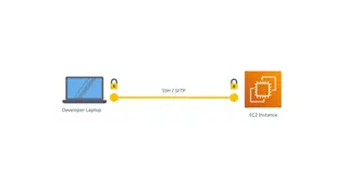
Connect Controller Connect power to the controller 12V ~1A Connect the controller to the network Use a network switch or crossover cable Ethernet Switch AAN-100 APACS PC
Check Operation When everything is connected correctly, check the LEDs to confirm proper operation
Program the IP Address InitAAN utility to program Ping to confirm
Connect Reader Interface Connect the AIM-4SL reader interface to the first communication port Use crossover wiring (T>R, R>T) Set address of AIM-4SL with DIP switch
Connect Reader Follow reader instructions to connect wires for power, comms and LEDs/buzzer READER 3 CONNECTION Yellow LED (If used) Brown LED Red +5 VDC Green Data 0 White Data 1 Yellow Buzzer Orange LED Black Ground Door Contact Switch (normally closed) Exit Push Button (normally open) Shield Auxilliary Input--Sensor (normally open)
Install Software Install from CD or download package from Apollo Website A key is required to use APACS Hardware key USB dongle that plugs into the PC Software key A file that is downloaded from Apollo s website after providing an activation code. Save the file in the APACS install directory.
System Configuration Launch System Configuration Default user/password: 1/1 Add PC Right-click system tree: Add Numberisn t needed IP Address of local PC, use numeric address or name
System Configuration Add the controller to the PC Network communication type Set IP Address in Communication Settings
Add Reader Add the reader to the controller The first reader on an AIM-4SL is always master (matches number on DIP switch) Select proper Port and Address If you don t have a door contact connected yet, go to hardware menu and unselect door contact control
Config Check Your system tree should now look like this:
Permissions Assign permissions to the default permissions set: 1 Make sure Message and Control permissions are granted for all objects
Check Global Settings Make sure global settings are correct for the system Click on root of system tree Save configuration
Start Communication Launch Alarm Mode If messages are displayed for Online then configuration is correct. Also check with Hardware Status
Test a Card Swipe a card at the reader A message should display with the result Card Format Error or Wrong Facility Code
Set Card Format Change Card Format in Controller Configuration to match the cards in use Set the bit length and facility code Save configuration and swipe the card again
Create Access Level Name the Access Level and then add reader/time zone Use the system time zone Always
Create User & Assign Access Level Use the card number to create a new user with card and assign the AL