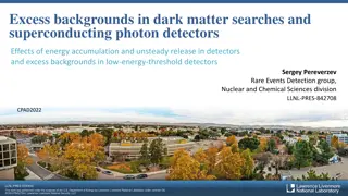
Advancements in Sapphire Detectors for Radiation Hardness Testing and High-Energy Physics Experiments
Reviewing radiation hardness testing, dose estimates, and measurements at LUXE, this content delves into the use of sapphire detectors in high-energy physics experiments. Highlighting sapphire's material properties, such as high radiation resistance, low cost, and specific characteristics, the text discusses intensive beam tests, experimental data on sensor exposure, MC simulations, and the potential for improved versions of sapphire detectors.

Download Presentation

Please find below an Image/Link to download the presentation.
The content on the website is provided AS IS for your information and personal use only. It may not be sold, licensed, or shared on other websites without obtaining consent from the author. Download presentation by click this link. If you encounter any issues during the download, it is possible that the publisher has removed the file from their server.
E N D
Presentation Transcript
GBP Radiation Hardness M. Bruschi (INFN Bologna) review of the results available and estimates of doses at LUXE possible measurements at Elbe (Rossendorf, Dresden (D)) TECHNICAL NOTE: https://www.dropbox.com/s/j9mz07he2s90w9o/LUXE_tech_note_final.pdf?dl=0 1
Why Sapphire? Sapphire is Al2O3 6 October Material properties density [g/cm3] bandgap [eV] energy to create an eh pair [eV] dielectric constant dielectric strength [V/cm] resistivity [Ohm cm] at 20 C electron mobility [cm2/(V s)] at 20 C MIP eh created [eh/ m] sapphire 3.98 9.9 27 9.3-11.5 4.0E+05 1.0E+16 600 22 diamond 3.52 5.47 13 5.7 1.0E+06 1.0E+16 2800 36 silicon 2.33 1.12 3.6 11.7 3.0E+05 1.0E+05 460 73 2024 M. Bruschi - INFN Bologna (Italy) S. Schuwalow et al.: Investigation of a direction sensitive sapphire detector stack at the 5 GeV electron beam at DESY-II / JINST 10 P08008 Specific characteristics of sapphire: High radiation resistance: ~ 10 MGy Leakage current does not increase with dose High eh creation energy Low collection efficiency (~10%) Fast response (low electron mobility compensated by reduced distance travelled by electrons) Low Cost: 1euro/cm2 (compared to diamond 3000 euro/cm2) 2
Tests on sapphire detectors Intensive beam tests for FLASH and XFEL (electron beams) Sapphire detectors have been intensively tested as beam halo and beam loss monitors at the Large Hadron Collider (CMS) A sapphire version of BCM has been intensively tested during RUN2 (BCML2 sapphire) and the performances can be compared with BCML2 pCVD diamond version Improved version (increased signal strength) of sapphire detector under consideration also for HL- LHC 6 October 2024 M. Bruschi - INFN Bologna (Italy) CERN-THESIS-2017-071 3
Experimental data available Two sensors of 10x10 mm2 size and 0.5 mm thickness have been exposed to intense 8.5 MeV electron beam at TU Darmstadt The CCE decreased to 30% relative efficiency after 12 MGy dose Recovery peaks are observed during beam off phases attributed to release of trapped charge carriers with a corresponding decay constant Leakage current after irradiation below 10 pA 4
MC simulation First station Upstream: 0.028 (0.036 including HI) Gy/BX Downstream: 0.052 (0.063 )Gy/BX x~0.8 mm y ~0.6 mm Only deposited energy by ionization considered In Si electrons need at least 260 keV to damage the bulk The minimum electron energy to damage sapphire is not available 5
Test Beam plans (2022 and beyond) 9-11 May 2022 Charge collection efficiency study (LNF): First on pads and then on detector prototypes Radiation hardness study (1-2 sensors)(ELBE). Beam requirements: ~ 2mm beam spot, el ~ 10 MeV, intensity > 105/bunch. Measure the sensor response vs time for the stable beam conditions until several MGy accumulated local dose. Control HV current (beam on/off). For several doses perform HV scan. Displace sensor wrt the beam and repeat measurements. Scan of metallized sapphire sensors for response uniformity study (LNF): all sensors before final installation. Beam requirements: ~ 2 mm beam spot, e- ~ 10 MeV, intensity 105 /bunch. Measured variables: signals from strips, current in the HV circuit. At several positions measure dependence of signal size on HV. Study of profiler performance in the narrow electron beam (DESY).Required beam spot size 0.1 mm. Sensor inclination wrt the beam allows to simulate elliptic spot shape. Make the detailed scan in the direction perpendicular to the strips and find reconstructed beam parameters. 06/10/2024 Fall 2022 Individual strip readout not necessary 2 days M. Bruschi - INFN Bologna (Italy) Fall 2022 Individual strip readout necessary ~1 week First quarter 2023 Individual strip readout necessary GBP movable table necessary ~ 1 week 6
Test Beam at ELBE Our proposal has been declared of scientific interest for the facility and approved Unfortunately, the war in Ukraine forced to changed plans Russian collaborators or products are not allowed in the test facility Proposal re-submitted https://www.dropbox.com/s/fnnjbk3pmnq3qlq/The%20beam%20monitor%2 0of%20the%20LUXE%20experiment_update.pdf?dl=0 The approval seems easy to get Re-scheduling expected for this fall 7
Goals of the ELBE Test Beam The use of the ELBE facility is probably indispensable for the high level irradiation tests CCE tests and uniformity of response tests can be done at LNF This test beam campaign is expected to investigate the degradation of the sapphire detector response and performances as a function of LUXE beam time the charge collection efficiency as a function of the absorbed dose the best sapphire manufacturer to be chosen for the BP LUXE detector production All this info will be of fundamental importance for tuning the detector simulation. 8
Experimental needs at ELBE Experimental setup: Three sapphire samples to be tested 1 sapphire wafer from University wafer dz~150 um, 4 strips 0.5x20 mm2 1 sapphire wafer from Cristal company dz~150 um, 4 strips 0.5x20 mm2 1 sapphire wafer company in Wuppertal dz~105 um, 4 strips 0.5x20 mm2 Very basic support printed circuit board (PCB) with signal output on RG58 type cable. Given the signal charge (tens of pC) the readout setup can be also placed in a safe area and the signal acquired during the irradiation The 4 channels can be readout by a scope or with other system to be decided. It is important the possibility to record signals amplitude and duration and also the charge of the signals (for CCE measure) and the HV currents as well. All the setup must be placed in a safely reachable area or otherwise remotely controlled. Remote control of all the setup is in any case advisable (also in case the system is accessible directly during irradiation) Signals should be recorded after interval of 1 MGy irradiation up to at least 10 MGy for each sample. 10 MGy is indeed the expected dose in the BP for 1 year of LUXE running. The set of BP detectors is expected to be changed approximately each year. Also important to take data at different HV (at least 4 different voltages) Given the steep worsening of the detector response with the absorbed dose, probably some more data points in the first MGy should be taken. Dose monitoring via ionisation chamber whichis is a PTW 34001 (https://www.ptwdosimetry.com/en/products/roos-electron-chamber/ https://www.rpdinc.com/ptw-34001-035cc-roos-electron-chamber-978.html) controlled by a PTW Unidos with 1 fA resolution 9
Beam time requested The energy of the electron beam particles is not critical, 25-30 MeV will be fine. If a beam spot area 5 mm^2 is assumed, then a 10 nA beam to get local dose rate 1 MGy/hour is needed. For signal measurement resolved bunches of 10^6 electrons per bunch may be assumed. Probably both requirements are compatible if ~ 80 kHz bunch repetition rate is assumed. The measurement scheme would be then the following: HV is measured during irradiation to check the radiation effects After ~1 hour of irradiation, the signal shapes signal are measured This should be repeated 10 times for each sensor. In order to fully achieve this 48 hours of machine time are needed (2 full days, with 2 shifts of 12 hours each). It is assumed that 6-8 people provided by the proponent groups can do this program. Support from the ELBE staff will be also necessary in preparing the test setup and configuring the beam line settings. 10
Beam parameters (ELBE) Beam Area S= 5mm2 (Assume uniform irradiation) e- per BX = 1E6 BX/s = 80000 Beam current: ~10 nA e-/s=8E10 E/s= 8E10x 50000x1.6E-19 = 6.4E-4 J/s V=0.05 x 0.01 cm3= 5E-4 cm3 M=4 g/cm3 x 5E-4 cm3=2E-6 kg Dose=E/M=6.4E-4/2E-6=320 Gy/s ~1 MGy/h 11
1 cycle on 1 sample Beam Meas/Changes Total per Meas Total Integrated Dose (MGy) T (min) 6 6 12 24 12 60 60 60 60 60 60 60 60 60 T(min) 10 10 10 10 10 10 10 10 10 10 10 10 10 10 T(min) 16 16 22 34 22 70 70 70 70 70 70 70 70 70 T(min) 16 32 54 88 110 180 250 320 390 460 530 600 670 740 0.1 0.2 0.4 0.8 1 2 3 4 5 6 7 8 9 10 Total duration ~ 13 h 3 samples in parallel could be considered Need 12 oscilloscope channels for histogramming HV scan also needed ! We are short on time! 12
Backup 13


")


")