Understanding Thermal Radiation and its Effects
Thermal radiation, studied by Isidoro Martínez during the COVID-19 pandemic, explores the transfer of heat through conduction, convection, and radiation. It delves into the concept of thermal effects of radiation, blackbody radiation, and related laws like Planck's law, Stefan-Boltzmann's law, and Wien's displacement law. The discussion also covers the spectrum of electromagnetic radiation, radiation-matter interaction, and the characteristics of thermal radiation in various applications.
- Thermal radiation
- Heat transfer
- Electromagnetic radiation
- Blackbody radiation
- Radiation-matter interaction

Download Presentation

Please find below an Image/Link to download the presentation.
The content on the website is provided AS IS for your information and personal use only. It may not be sold, licensed, or shared on other websites without obtaining consent from the author. Download presentation by click this link. If you encounter any issues during the download, it is possible that the publisher has removed the file from their server.
E N D
Presentation Transcript
Thermal radiation by Isidoro Mart nez (prepared during coronavirus pandemic confinement) 2020-March-25th
Heat Temperature differences cause heat flows (note that heat is only defined at a given surface, and that adiabatic wall is a limit). Heat flows: By conduction through solids. At a surface it is By convection, i.e. by heat conduction within a fluid. At the wall, Normal use of bulb thermometers. By radiation (i.e. electromagnetic coupling through vacuum or semi-transparent materials, instead of by material contact). It may disturb Tfluid-measure (needs shrouds; sky-T frost ), but it allows non-contact thermometry, and it is crucial in space. For a convex surface seeing only a large enclosure, Radiation heat flow between two isothermal surfaces in vacuum, A1and A2(in a general case where there are other surfaces participating), not only depends on T1and T2but on all other temperatures (incoming radiation to A1may come from A2by emission and by reflection from other surfaces). Exercise P-13.31 illustrates that a net heat flow may exists between A1and A2even with equal temperatures (T1= T2), contrary to the idea of heat transfer. Do not confuse thermal radiation ( T4) with radiation heat transfer ( T). = q k T . ( ) = q h T T w ( ) = 4 4 q T T . w
Radiation Radiation (Lat. radius, rod) may have thermal and non-thermal effects, and may be: Immaterial (electromagnetic radiation, EMR): rays, waves, photons. Material (particle radiation): electrons, -rays, -rays, solar wind, neutrons. Thermal radiation is the EMR emitted by the thermal motion of electric dipoles (& multipoles) in matter, in the long field (L> =10 m). All types of radiations (EMR and particulate) have thermal effects, but we focus on heat transfer by thermal radiation under vacuum. We leave aside applications of thermal radiation to thermometry, thermal signature, remote sensing, lighting, telecommunications, power plants, propulsion, fire control, climate change, etc. Radiation-matter interaction: emission, transmission (rays at speed c), reflexion, refraction, directional dispersion, spectral dispersion, absorption, emission...
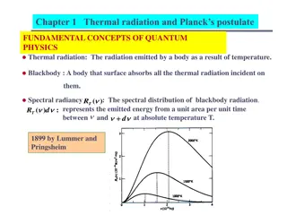
Blackbody radiation BB-radiation is the EMR inside a cavity of an isothermal material, equal to that escaping through a small hole in the cavity, and characterised by its temperature T and Planck s spectral distribution of photon energies (E=h =hc/ ): 2 2 hc M hc kT A = = bb, B T 5 5 exp 1 exp 1 This Bose-Einstein distribution of photon frequencies, like Maxwell-Boltzmann distribution of molecular speeds in a gas, are due to entropy maximization at equilibrium, for a given energy. EM-spectrum:
Power Thermal radiation, like any EMR, is mainly characterised by power (total amount, [W], or flux, [W/m2]), and photon frequency (E=h =hc/ , where is frequency and wavelength). Universal constants: h=6.6 10-34J s, c=3 108m/s, k=1.38 10-23J/K. Planck s law has two corollaries: ( ) = = = 4 8 2 4 d 5.67 10 W/(m K ) M M T Stefan-Boltzmann s law: bb, bb 0 = = = d /d 0 ( 0.0029 m K) Wien s displacement law: M C T C bb, ,max M bb, Examples: A body at about 5800 K (the Sun) emits 64 MW/m2in a spectral band around =0.5 m, with 98 % of it in =0.3..3 m (10 % UV, 40 % visible, 50 % IR). Bodies around 300 K (all common objects) emit 300..1000 W/m2in a spectral band around =10 m. Bodies at cryogenic temperatures, say Tb,H2=20 K, emit less than 10 mW/m2in a spectral band around =150 m. To evacuate 1 W from TLH2=20 K to TCBR=2.7 K one needs a radiator of >100 m2.
Fig. 1. Solar irradiance spectrum above Earths atmosphere (total 1361 W/m2, beam), and at the surface, subsolar, on a clear-sky day (900 W/m2beam and 90 W/m2diffuse).
Thermal effects of non-thermal radiation Thermal radiation has a large spectral band, say 10-7< [m] < 10-3. EMR of larger may have thermal effects (e.g. microwaves, at =0.12 m, f=2.4 GHz, heats polar molecules, and susceptors), but it is not thermal radiation (i.e. it is not emitted by thermal motion). Individual photons have so Little energy that they must be detected in groups by means of relatively large antennas (proportional to ). EMR of smaller may have thermal effects, but their interaction with matter is so energetic that its absorption not only yields thermal vibrations of molecules, but dissociation and ionization. Ionising radiation (EMR and particulate) usually has deleterious effects on living matter (and on electronics), but can also be advantageously used (e.g. X-ray in medicine).
Radiance Source (emitter): Emittance, M=d /dA [W/m2]; Mbb= T4. Emissivity, =M/Mbb. Radiance, L=d2 /(dA d ) [W/(m2 sr)]. Sink (detector, absorber): Radiance, L=d2 /(dA d ) [W/(m2 sr)]. Irradiance, E=d /dA [W/m2]; Absorptance, ,T, L ,T, ,abs/L , ,incid. Fig. 2. Radiation magnitudes. cos d E L 2 Cosine law (geometric considerations) Blackbody radiation escaping from a hole, issues with a cosine-law intensity to the normal. Collimated radiation incident on a surface, varies as E=E0cos ( being zenith angle).
Energy balances Reversibility of detailed equilibrium: ,T, = ,T, (Kirchoff s law). Also ,T, , = ,T, , . Balance at a surface: + + =1 (we will assume =0, opaque surfaces). Exitance (radiosity): total exiting radiation is emission plus reflexion: M= Mbb+ E . Directional models Diffuse model (Lambert): intensity [W/sr] cos , for emission (like a blackbody), and for reflection. Diffuse surfaces produce isotropic radiance, and then = MdA= LdA d M= Lcos d =L cos 2 sin d = L (to be used in view factors). Others: specular, retroreflective, combined. Transparent, translucent. Spectral model (two bands) Solar band ( =0.3..3 m; only is of interest), & Far-infrared band, FIR, ( =3..30 m, where we assume FIR= ). Notice that, in general . At T<50 K emissivity decreases a lot. Notice that ISO 20473-2007, defines FIR for =50..1000 m, but we prefer here to center NIR-, MIR- & FIR-bands in atmospheric windows.
Lumped network model (LNM) Discretization of the system in isothermal surface elements. General energy balance, and thermal balance (assuming E=Eth+Eeke+EEM): d d d d d d d d d d t E E E t = + + = + = + + + + ele t th t W Q m h W W Q Q Q e e EM ele cond conv rad E ( ) ( + ) = ele t T W EM,out W EM,dis W W W W EM,in ele,in ele,out ele,dis = 0 m = + + + + = + + + C W W Q Q Q W Q rad,net,int Q rad,net,ext Q em,dis ele,dis cond conv rad dis cond where rad,int refers to spacecraft nodes, and rad,ext to external exchanges (with the Sun, planet or moon, and background space).
Radiation heat transfer ( ) t W In nodal equations, thermal capacity, C, is data, is known (from operational data), conductive couplings are computed as: ( cond, 1 j = dis k A j i = j i = ) ( ) N N ij L ij Q G T T T T i ij j i j i = 1 j ij internal radiative couplings, in the case of blackbody surfaces, are: N N ( ) ( ) = = 4 j 4 4 j 4 rad,int,i Q R T T AF T T ij i i ij i = = 1 1 j j where Fijare view factors, later explained, as well as the extensi n to non-blackbody surfaces), and the external radiative couplings: Q Q Q Q = + + Q rad,ext, s, a, p, , i i i i i
View factors The view factor F12is the fraction of energy exiting an isothermal, opaque, and diffuse surface 1 (by emission or reflection), that directly impinges on surface 2 (to be absorbed, reflected, or transmitted). Assuming they see each other (0 /2), the power reaching dA2from dA1is the product of its radiance L1=M1/ , times the perpendicular area dA1 , times the solid angle subtended by dA2, d 12; i.e. d2 12=L1dA1 d 12=L1(dA1cos( 1))dA2cos( 2)/r122, hence: ( ) ( ) 1 12 1 1 1 12 12 12 1 1 1 1 d d M M ( ) ( ) ( ) ( ) d d cos cos cos d cos cos cos L 2 d = = = = 1 2 2 1 2 d d d F 2 2 2 12 r 12 r cos cos 1 A = d d 1 2 F A A 12 2 1 2 12 r 1 A A 1 2 Fig. 3. Geometry for view-factor definition.
View factor algebra When considering all the surfaces under sight from a given one in an enclosure, the following general relations apply: Bounding. View factors are bounded to 0 Fij 1 by definition. Closeness. Summing up all view factors from a given surface i gives unity, Fij=1. Reciprocity. AiFij=AjFji. Distribution. When two target surfaces (j and k) are considered at once, Fi,j+k=Fij+Fik. Composition. Based on reciprocity and distribution, Fi+j,k=(AiFik+AjFjk)/(Ai+Aj). Notice that F12is proportional to A2but not to A1. Try a composition exercise. Areas need to be clearly identified (e.g. a plate of 1 m in side may be 1 m2or 2 m2). For an enclosure formed by N surfaces, there are N2view factors (each surface with all the others and itself). But only N(N 1)/2 of them are independent.
The crossed-string method for 2D view factors The view factor between two infinitely-long bands, 1 and 2, of cross-section length L1and L2(Fig. 4), can be computed by the simple crossed-string method (lengths of tense ropes): crossed strings 2 L uncrossed strings source string + L L L L = = 4 5 3 6 F ( ) 12 2 1 Fig. 4. Sketch of crossed string method (notice that string length must include curved segments).
Examples of view factors 2D, e.g. between two concentric hemi-cylinders of radii R1and R2>R1. 2 2 2 L + = + 2 1'2" L 1"2' L L 1"2"' L 1"2' L 1"2"' L 1"2' L 1"2"' L = = = = 1'2' F 12 L L 1'1" 1'1" 1'1" R R 2 ( ) 2 2 2 arccos R R R R R 1 + 3 1 1 1 2 1 = = 2 R R 3 2 1 2 = 0.90 R 1 3D, e.g. sphere of radius R1to concentric hemisphere of radius R2>R1(tables).
Exitance Exitance method method It solves the radiative heat transfer between gray surfaces in the lumped network model. Besides isothermal nodes, it requires the surfaces to be opaque, diffuse (for emission and reflection), and in vacuum (or non-absorbing media). Only the FIR spectral band is considered (solar inputs are dealt with separately). For more general radiative exchanges, a Monte Carlo statistical approach must be followed (like in ESATAN). The driving force for radiative exchange is exitance, that for FIR is, M= Mbb+ E= Mbb+(1 )E= Mbb+(1 )E. The energy flow and resistance between nodes is: ( ,rad ,rad , i j j i i j j j j i j j j M M ) ( ) ( ) j i = = = = = Q Q M A F M AF M AF M AF 1 , , , i i i i j j i i j i i i j j j AF , i i j
Exitance Exitance method method (cont.) The relation between exitance, M, and temperature, T (or, better, blackbody emittance, Mbb= T4) is: = int. = 1 4 AE AM AE A T M M IR,1 1 1 1 1 1, IR,1 1 1 1 1 bb = = = 1 1 1, bb Q Q IR,1 1 1 1 ( ) ext. = ( ) = 1 + 4 1 AE AM AE A T AE 1 1 1 1 1 1 1 1 1 IR,1 1 1 A 1 1 hence, one finally arrives at a a set of triple nodal equations with the three unknowns , Mi, and Mi,bb(or Ti): = = i Q ,rad M M M M d d T t j i = ,bb i i i Q C i,cond Q W 1 1 ,rad i,dis i i i j i i AF A i ij Try Exercise P-13.50 & Exercise P-13.51
Exitance Exitance method method (cont.) In the special case of just two nodes in the enclosure, there is an explicit solution: 4 2 1 12 1 1 1 A AF 4 T T = Q 1 + + 2 A 1 1 1 12 2 2 ( ) ) ) 1 1 A 4 4 T T 2 1 = Q which, if one is convex (F12=1), reduces to: 12 1 1 A A ( 2 ( + 1 1 2 2 2 T In the simple case of two parallel surfaces with equal emissivity, it is: Try Exercise P-13.61 & Exercise P-13.63. 4 4 A T 2 1 = Q 12
= + + rad,ext, Q Q Q Q Q External radiation exchanges s, a, p, , i i i i i Q Solar direct beam, have just the thermal effect. If is the electrical efficiency, and only a fraction Fpqof the area is covered with solar cells, thermal absorption is: ( s, pq ,fr es ee i i i i Q F A E F = = , is partially absorbed, but photovoltaic production must be subtracted to s,i ) A E F es ee ,th ,fr i i where Afris Sun s facing frontal area, and the last factor, 0<F<1, is to take account of eclipses. Albedo, i.e. solar indirect, reflected in other bodies. Bond-albedo is implied (i.e. total hemispherical reflection fraction of incident solar radiation), not geometric-albedo (which is normal reflectance, and may be >1). Maximum albedo is at noon, and it is usually approximated as a cosine of angular position in orbit, . In terms of the orbit solar angle , albedo absorption is: cos i i i i th Q Q F Q = = AF E a, a, ,0 a, ,0 , i ip p 3 , 2 2 where Fipis the view factor from surface Aito the planet, pis planet albedo, and E is solar irradiance. See an exercise with solar reflection. Planet infrared exchange, and Cosmic-Background infrared exchange. (next.)
Planet infrared exchange, and Cosmic-Background infrared exchange Two approaches may be followed (with the same result): If the planet (or moon) term is considered to account only for the gross infrared input (OLR), then the infrared output to cosmic-background must include the planet view factor, i.e.: 4 p, , & i i i ip p p i Q AF T Q = ( ) = + 4 A F F T i i i ip i If the planet (or moon) term is considered to account for the net infrared input, then the infrared output to cosmic-background must not include the planet view factor, i.e.: ( p, i i i ip p p i Q AF T T = ) = 4 4 4 & Q AF T , i i i i i Planets with atmosphere appear larger (e.g. REarth=6371 km Reff,rad=6390 km). Planet and moon properties, aside. Question: what is larger at LEO, ? or planet Q albedo Q
Spacecraft missions and thermal effects Mission phases. Type of payloads. Type of orbits: LEO. H=250..1200 km, To=89..109 min (max.eclipse 34..37 min). Try Exercise P-13.72. SSO, near polar LEO with orbital plane (i=98..102 ) moves keeping an invariant position relative to Sun. MEO, H=20 000..23000 km, To=12..14 h (max.eclipse 55..58 min). GEO, H=35 790 km, To=23,9 h (max.eclipse 70 min, penumbra 2+2 min). Halo. Sun-Earth halo orbits, at RSs/RSE=1 0.01, have most stable thermal environment. SEL2 is slightly beyond Earth s umbra. Transfer (e.g. to GEO, to the Moon, to Mars, to the Sun ). Try Exercise P-13.66. Orbit projection to better analyse termal inputs: a) view from above orbital plane, b) view from above satellite (best for angle), c) view from the Sun. is the orbit-plane inclination to Sun rays.
Spacecraft thermal modelling Thermal control is needed to avoid damaging too-hot or too-cold tempeeratures in all parts at every moment. Basically, to keep a delicate balance between the deep-freeze of empty-space and the Sun's blazing heat. Thermal insulation, mainly based on multilayer radiation shields, is most used, but perfect isolation is impossible and in many cases undesirable (internal heat must be evacuated). Most thermal problems occur under transient conditions associated to eclipse, manoeuvres, attitude change, payload operation, etc. However: Transient problems are complicated, and spacecraft thermal control design usually analyse only two steady-state cases: Worst hot case; e.g. in LEO E=1361+50 W/m2, albedo 30+5 %, OLR 240-30 W/m2(not all worst)., plus a 10 % step during say 10 min. Hottest operational case (HOC) is used to dimension radiators. Worst cold case; e.g. in LEO E=1361-50 W/m2, albedo 30-5 %, OLR 240+30 W/m2(not all worst), minus a 10 % step during say 10 min. Coldest operational case (COC) is used to dimension heaters. An average orbital steady-state with the orbit-averaged inputs, although not a design limitation, provides a first guide to find the orbit-averaged temperature. Transients can be analysed solving the thermal balance with the temporal functions (usually in angular variables) for solar-direc, albedo, and power dissipation. Back to Spacecraft Thermal Control.


")
")