Understanding Propeller Blade Geometry and Airfoil Sections
Explore the intricate details of propeller blade geometry including diameter, number of blades, skew, clearance, helix pitch, and blade shape variations. Learn about the National Advisory Committee for Aeronautics (NACA) and its contributions to airfoil design. Dive into the complexities of propeller engineering and the significance of different blade sections in optimizing performance. Discover how blade shape variations can impact cavitation control and efficiency in propeller design.

Download Presentation

Please find below an Image/Link to download the presentation.
The content on the website is provided AS IS for your information and personal use only. It may not be sold, licensed, or shared on other websites without obtaining consent from the author. Download presentation by click this link. If you encounter any issues during the download, it is possible that the publisher has removed the file from their server.
E N D
Presentation Transcript
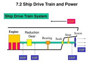
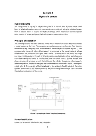
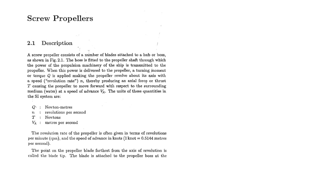
D : Diameter Z : Number of Blade Left Prop: Anti Clockwise turns Right Prop: Clockwise Turns Helix: Pitch: Sides: Back/Suction/Low Pressure Face/Pressure/ High Pressure DD
Skew: Joining the midpoints between leading and trailing edges at different radii. Clearance <90 Degrees 0 Degrees 0-30 Degrees
SSkew: Joining the midpoints between leading and trailing edges at different radii. Example
SCylindrical Coordinate System: (r, , z) is used. Axial Velocity: VA Tangential Velocity: 2 nr ( r) Propeller Geometry Pitch Angle: ? = tan 1? 2?? x=rcos , y=rsin , z=z
Blade Blade Area Area
Blade Blade Shape Shape The blade shape can be varied to even out the cavitation along radius and in the case of a nozzle propeller, it is advantageous to have wide-chord length at the tip (Kaplan shape).
National Advisory Committee for Aeronautics (NACA). Old name of today s NASA (The National Aeronautics and Space Administration) Propeller Blade Sections Airfoil geometry can be characterized by the coordinates of the upper and lower surface. It is often summarized by a few parameters such as: maximum thickness, maximum camber, position of max thickness, position of max camber, and nose radius. One can generate a reasonable airfoil section given these parameters. This was done by Eastman Jacobs in the early 1930's to create a family of airfoils known as the NACA Sections. Public Domain Aeronautical Software - http://www.pdas.com/ http://airfoiltools.com/
The NACA 4 digit and 5 digit airfoils were created by superimposing a simple meanline shape with a thickness distribution that was obtained by fitting a couple of popular airfoils of the time: +- y = (t/0.2) * (.2969*x0.5- .126*x - .3537*x2+ .2843*x3- .1015*x4) The camberline of 4-digit sections was defined as a parabola from the leading edge to the position of maximum camber, then another parabola back to the trailing edge. NACA 4-Digit Series: NACA 4412 4 4 1 2 max camber position max thickness in % chord of max camber in % of chord in 1/10 of c
After the 4-digit sections came the 5-digit sections such as the famous NACA 23012. These sections had the same thickness distribution, but used a camberline with more curvature near the nose. A cubic was faired into a straight line for the 5-digit sections. The 6-series of NACA airfoils departed from this simply-defined family. These sections were generated from a more or less prescribed pressure distribution and were meant to achieve some laminar flow. After the six-series sections, airfoil design became much more specialized for the particular application. Airfoils with good transonic performance, good maximum lift capability, very thick sections, very low drag sections are now designed for each use. Often a wing design begins with the definition of several airfoil sections and then the entire geometry is modified based on its 3-dimensional characteristics.
Profile Sections Profile Sections NACA16 T/C 0.25000 0.39767 0.52893 0.75848 0.90483 0.98212 1.00476 1.00000 0.97580 0.90280 0.77740 0.68900 0.57620 0.50540 0.41820 0.30080 0.21540 0.00000 NACAa0.8 F/C 0.00000 0.18408 0.30426 0.47480 0.58631 0.65283 0.67896 0.67696 0.66442 0.60370 0.47713 0.36826 0.24349 0.17941 0.11626 0.05586 0.02725 0.00000 NACA16 AND NACA66 Thickness and NACA a0.8 Meanline distributions are commonly used in commercial design propellers i X/C 1 2 3 4 5 6 7 8 9 10 11 12 13 14 15 16 17 18 0.00000 0.05000 0.10000 0.20000 0.30000 0.40000 0.50000 0.55000 0.60000 0.70000 0.80000 0.85000 0.90000 0.92500 0.95000 0.97500 0.98750 1.00000 T/C&F/C GRAPHS 1.50000 1.00000 0.50000 0.00000 0.000000.200000.400000.600000.800001.00000 T/C F/C
Frame 001 26 Sep 2005 0.12 0.11 0.1 0.09 r/R=1.000 r/R= .950 0.08 r/R= .900 r/R= .850 0.07 r/R= .800 0.06 r/R= .700 y(m.) r/R= .600 0.05 r/R= .500 0.04 r/R= .400 0.03 r/R= .300 r/R= .250 0.02 r/R= .230 0.01 0 -0.01 -0.02 -0.075 -0.05 -0.025 0 0.025 0.05 0.075 x(m.) Frame 001 25 Sep 2005 3D PROPELLER GEOMETRY DEFINITION Z X Y PITCH AND CHORD DISTRIBUTIONS 0.08 0.06 1.40 0.04 1.20 0.02 1.00 P/D, c/D 0 P/D c/D 0.80 Z 0.60 -0.02 0.40 -0.04 0.20 -0.06 0.00 0.05 0.00 0.20 0.40 0.60 0.80 1.00 1.20 -0.08 0 Y r/R 0 X -0.05 -0.025
Then, the following geometrical parameters of the profile are to be determined; Profile chord distribution Mean line or camber distribution ( ) c r M f c ( ) r Profile max. thickness distribution tr c ( ) Pr D Pitch ratio distribution ( ) P Pitch angle distribution = ( ) r tan2 arc r