Time Distribution System R&D Update for Hyper-Kamiokande Experiment
In the February 2020 update, Stefano Russo from LPNHE Paris presented the progress on the time distribution system R&D for the Hyper-Kamiokande experiment. The focus is on implementing a bidirectional data exchange link with a large bandwidth capacity for synchronous, phase-deterministic protocol. Two promising solutions, CERN White Rabbit and Custom Solution based on FPGA, were evaluated. CERN White Rabbit offers a fully deterministic gigabit ethernet-based solution with single master-many slaves architecture, while the Custom Solution utilizes FPGA for point-to-point communication with tailored bandwidth. Architectures for both solutions were discussed with considerations for bandwidth requirements. Additional bandwidth beyond the requested 100 Mbps is deemed beneficial for the project.

Uploaded on Oct 03, 2024 | 0 Views
Download Presentation

Please find below an Image/Link to download the presentation.
The content on the website is provided AS IS for your information and personal use only. It may not be sold, licensed, or shared on other websites without obtaining consent from the author. Download presentation by click this link. If you encounter any issues during the download, it is possible that the publisher has removed the file from their server.
E N D
Presentation Transcript
February 2020 update on the time distribution system R&D for the Hyper-Kamiokande experiment stefano russo LPNHE Paris, HK meeting 06/02/2020
What Do We Need? The HK requirements call for a bidirectional data exchange link The requested bandwidth seems low (100 Mbps?) Extra bandwidth can be useful The goal is to implement a synchronous, phase deterministic protocol with a large bandwidth
How Do We Implement it? R&D started. Many solutions have been evaluated and 2 of them seem promising CERN White Rabbit Custom solution
CERN White Rabbit Fully deterministic gigabit ethernet-based solution to distribute data and time Single master many slaves The master receives a reference, generates a clock and distributes it Propagation delay actively compensated Synchronization requires very few bandwidth (~400 Bps) White Rabbit node can talk with standard ethernet nodes 18 ports white rabbit switches are off-the-shelf CERN distributes hardware and firmware design and support them
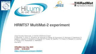
CERN White Rabbit A possible architecture 8* links 8* links DAQ WR switch WR switch FE FE FE FE 24 24 24 24 8* 8* * These numbers depend on the bandwidth
Custom Solution Based on FPGA s ser-des fixed phase locking system Point-to-point Each master can receive a reference or a fast clock, generates a clock and distributes it Synchronization doesn t require any data bandwidth Slave s clock phase delay is proportional to the signal propagation Custom FE link with tailored bandwidth DAQ link is standard (i.e. 10Gbps ethernet) Concentrator connections depends on the requested bandwidth Hardware and firmware design is custom
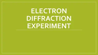
Custom Solution A possible architecture (assuming 1Gbps to FE) 10 Gbps Eth 10 Gbps Eth DAQ Alternative CLK fanout Custom Concentrator Custom Concentrator FE FE FE FE 24 24 24 24 8* 8* * These numbers depend on the bandwidth
R&D status First results on the White Rabbit link clock performances Ideas about the UTC time tagging
White Rabbit R&D We focused our attention on the distributed clock performances once verified that the available data bandwidth is compliant with the 1Gbps specs The tests have been done on a couple of custom made boards white rabbit compliant All the presented work as been done in collaboration with INFN Rome-1 branch in the lab directed by Fabrizio Ameli who made the biggest part of this study
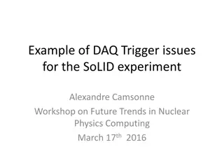
White Rabbit R&D PPS total jitter = 17.96 ps
White Rabbit R&D The total jitter on reconstructed clock is 67.26 ps RMS The biggest part is concentrated between 1 and 10 Hz (annoying, PLLs don t work very well in this range)
White Rabbit R&D next steps A new set of boards with new features is under development. We are designing a mezzanine card with the WR circuitry to be plugged on the FE prototypes. With this mezzanine any FE can perform both clock distribution solutions. We have acquired a WR switch to test its performances. The exchange with the CERN WR group is ongoing.
Time tagging The goal is to distribute a precise time reference to entire system and associate it with the UTC. The idea is to use a very stable source (atomic clock) and correlate it with UTC via the Global Navigation Satellite System (GNSS). The main problem is the distance between the antenna (and the GNSS receiver) and the HK electronics (2/5 Km?) The complexity of the system (and its price) depends on the needed accuracy
Time tagging main components An atomic clock to generate a stable and precise local reference. A GPS receiving system to refer the local time to UTC. A computer to correct the UTC from the GNSS using data from a time laboratory (UTC(k) data).
time tagging first scheme GNSS receiver Time Atomic clock distribution One idea could be to have the local clock reference where the GPS receiver is and send its clock and PPS to the cave using a calibrated network (WR or other solutions).
Time tagging second scheme GNSS receiver Time distribution Atomic clock Another idea could be to have the local reference in the cave and send it to the receiver outside. (Bigger uncertainty on the UTC)
Time tagging open points The complexity of the system depends on the precision and accuracy we want to achieve in terms of: Stability and precision of the local clock. Accuracy respect to the UTC. What precision and accuracy we need? How we associate our events to the accelerator? We have recently established a good collaboration with the SYRTE lab in Paris responsible for the official France time and part of the UTC labs network