Understanding the Function and Evolution of Flywheel Mechanism

A flywheel is a crucial component that stores energy as kinetic energy through rotation. It plays a vital role in various applications, from early pottery wheels to modern energy storage systems. As the main energy source diminishes, the stored energy in the flywheel is released to provide uninterrupted power. Over time, flywheels have evolved into complex constructions, enabling diverse uses such as supplementary UPS storage and enhancing renewable energy solutions.

Download Presentation

Please find below an Image/Link to download the presentation.
The content on the website is provided AS IS for your information and personal use only. It may not be sold, licensed, or shared on other websites without obtaining consent from the author. Download presentation by click this link. If you encounter any issues during the download, it is possible that the publisher has removed the file from their server.
E N D
Presentation Transcript
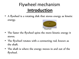
Flywheel mechanism Introduction A flywheel is a rotating disk that stores energy as kinetic energy. Flywheel The faster the flywheel spins the more kinetic energy it stores. The flywheel rotates with a connecting rod, known as the shaft. The shaft is where the energy moves in and out of the flywheel.
Introduction As the main source of energy decreases, the energy stored in the flywheel is released. Flywheel stores energy when the supply is in excess. Mechanisms will receive an uninterrupted supply of energy.
Introduction One of the earliest uses of the flywheel was in the potter s wheel. A potter s wheel is a mechanism with a rotating turntable on top where the clay is shaped. There is a pedal that must be pressed and released in order to power the turn table. A shaft from the turntable to the pedal has a flywheel attached. The flywheel provides uninterrupted, steady rotation of the turntable between pedaling.
N= Introduction As the person operating the potter s wheel presses down and releases the pedal, the flywheel keeps the turntable moving at a constant speed.
Introduction The operator could even stop pedaling and the turntable would keep moving due to the energy stored in the flywheel. The convenience of the flywheel allows the potter to form the clay without problems caused by an uneven rate of spinning. The early models where consisting of only a stone wheel attached to an axle. purely mechanical
Introduction Nowadays flywheels are complex constructions where energy is stored transferred to and from the flywheel by an integrated motor/generator. The stone wheel has been replaced by a steel or composite rotor and magnetic bearings have been introduced. mechanically and
Introduction Today flywheels are used as supplementary UPS storage at several industries world over. Future applications span a wide range including electric vehicles, intermediate storage for renewable energy generation and direct grid applications from power quality issues to offering an alternative to strengthening transmission.
Introduction Today flywheels are used as supplementary UPS storage at several industries world over. Future applications span a wide range including electric vehicles, intermediate storage for renewable energy generation and direct grid applications from power quality issues to offering an alternative to strengthening transmission.
Introduction So far flywheels over 10 kV have not been constructed, mainly due to isolation problems associated with high voltage, but also because of limitations in the power electronics. Recent progress in semi-conductor technology enables faster switching and lower costs.
Introduction More recent improvements in material, magnetic bearings and power electronics make flywheels a competitive choice for a number of energy storage applications. The progress inpower electronics, IGBTs and FETs, makes it possible to operate flywheel at high power, with a power electronics unit comparable in size to the flywheel itself or smaller.
Introduction The use of composite materials enables high rotational velocity with power density greater than that of chemical batteries. Magnetic bearings offer very low friction enabling low internal losses during long-term storage. High speed is desirable since the energy stored is proportional tothe square of the speed but only linearly proportional to the mass.
Introduction There are a number of attributes that make flywheels useful for applications where other storing units are now used. High energy density. High power density. No capacity degradation, the life time of the flywheel is almost independent of the depth of the discharge and discharge cycle.
Introduction The state of charge can easily be measured, since it is given by the rotational velocity. No periodic maintenance is required. Short recharge time. Scalable technology and universal localization. Environmental friendly environmental impact. materials, low
Introduction Individual flywheels are capable of storing up to 500MJ and peak power ranges from kilowatts to gigawatts, with the higher powers aimed at pulsed power applications.
Introduction In intermittent like punching machines, shearing machines, riveting machines, crushers etc., the flywheel stores energy from the power source during the greater portion of the operating cycle and gives it up during a small period of the cycle. machines where the operation is
Introduction Punching machine Thus the energy from the power source to the machines is supplied practically at a constant rate throughout the operation.
Introduction Modern flywheels are a bit different from the ones that were popular Revolution. Instead of wide and heavy steel wheels with even heavier steel rims, 21st-century flywheels tend to be more compact and made from carbon- fiber or composite materials, sometimes with steel rims, which work out perhaps a quarter as heavy. during the Industrial
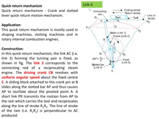
flywheel mechanism Background consider the slider-crank mechanism that moves in a horizontal plane as shown below.
The mechanism may be driven by a torque flywheel mechanism at O or a force on the slider (or piston) at B. Assume the mechanism is driven by a torque at O. It can be shown that T the kinetic energy of the mechanism may be written as
Here, Igen is the generalized inertia of the system associated with the crank rotation inertia of the mechanism (and hence its kinetic energy) is position dependent If we now assume that the mechanism has negligible friction and is given some initial kinetic energy and allowed to rotate freely (i.e. with no driving torque), then (by conservation of energy) the kinetic energy of the mechanism must remain constant
flywheel mechanism The motion of the system vary with position to counteract the changes of inertia. Flywheels can be used to lower the motion fluctuations of a mechanical system. so that it will naturally resist moThe basic idea here is to add enough constant inertia to the system tion fluctuations from any source. The following sections develop equations for determining the inertia required for the flywheel to keep motion fluctuations within some specified limits.
flywheel mechanism Here, TLis the position varying load torqueTfis the friction torque and TM is the motor torque Consider the free-body diagram of theflywheel shown below. Fig.11 Summing moments on the flywheel gives M = TM Tf TL = IF a
Assuming that the motor torque just cancels the friction torque, then the above equation may be rewritten as Integrating this equation with respect to q gives The term on the left side of this equation represents the work done on the flywheel by the load torque, and the term on the right side is the change in kinetic energy of the flywheel
flywheel mechanism To decrease the angular velocity fluctuations of the flywheel associated with some load torque, its inertia must be increased. However, increasing the inertia of the flywheel also increases the amount of energy required to start or stop the system Coefficient of Fluctuation The coefficient of fluctuation (k) of the motion is defined as follows where max is the maximum angular velocity, min is the minimum angular velocity, and avg is the average angular velocity over some interval of motion
flywheel mechanism Sizing the Flywheel To size a flywheel for a given system, we equate the work done by the load torque to the work done by the torque required to drive the system at a constant speed The work done by the latter may be calculated from an inverse dynamic analysis. Suppose, for example that the torque curve for a complete cycle of the mechanism is as shown in the figure below The areas ( 1,2,3,4) i A i=represent the work done during certain portions of the motion. The largest of these are as represents the largest amount of work that must be supplied to the system (and hence, the largest potential swing in angular velocity).
Equating the largest area to the largest flywheel mechanism kinetic energy change of the flywheel gives The actual dimensions of the flywheel are determined by IF and the type of flywheel chosen.
flywheel mechanism DYNAMICALLY EQUIVALENT SYSTEM The slider-crank mechanism is one of the most commonly used mechanisms It is used in prime movers, reciprocating compressors, punching machine, press, etc. The reciprocating mass comprises mass of the piston and part of the mass of the connecting rod. In a general case, we can think of a rigid link of any shape as shown in Figure 12. Let this be subjected to a system of forces whose resultant is say F generating a couple Fe about center of gravity G. This force produces linear acceleration : and angular acceleration: WhereI is mass moment of inertia about a perpendicular axis through G
flywheel mechanism Let a1 and a2 be the distances of the point masses m1 and m2 from center of gravity G, respectively. For a dynamically equivalent system having accelerations a and .
flywheel mechanism The correction couple has to be determined and it will be , This couple can be thought of applied by the two forces FC as shown in Figure 13 Figure 13 : Slider Crank Mechanism
flywheel mechanism Turning Moment Diagram of a Single Cylinder 4-stroke IC Engine If the effect of correction couple is ignored, the approximate turning moment M = (Gas force + Inertia force) O2 D The diagram which is plotted for M against crank angle is called turning moment diagram. This diagram can be plotted progressively as explained below: (a) There are two forces, i.e. gas force and inertia force. Gas force = pXPiston area wherep is the gas pressure
flywheel mechanism Figure15(a The net force is the resultant of gas force and inertia force. It can be plotted in reference to as shown in Figure 15(b). Figure 15(b
Energy Stored in a Flywheel A flywheel is shown in Fig. 1.1. We have already discussed that when a flywheel absorbsenergy its speed increases and when it gives up energy its speed decreases. Let m = Mass of the flywheel in kg, k = Radius of gyration of the flywheel in metres, I = Mass moment of inertia of the flywheel about the axis of rotation in kg- m2 = m.k2, N1and N2= Maximum and minimum speeds during the cycle in r.p.m., w1and w2= Maximum and minimum angular speeds during the cycle in rad / s, N = Mean speed during the cycle in r.p.m.(N1+N2)/2 w= Mean angular speed during the cycle in rad / s= (w1+w2)/2 CS= Coefficient of fluctuation of speed=(N1-N2)/N or (w1+w2)/w
Stresses in a Flywheel Rim A flywheel, as shown in Fig. 1.2 consists of a rim at which the major portion of the mass or weight of flywheel is concentrated, a boss or hub for fixing the flywheel on to the shaft and a number of arms for supporting the rim on the hub. The following types of stresses are induced in the rim of a flywheel: 1. Tensile stress due to centrifugal force, 2. Tensile bending stress caused by the restraint of the arms, and 3. The shrinkage stresses due to unequal rate of cooling of casting. These stresses may be very high but there is no easy method of determining. This stress is taken care of by a factor of safety. Fig. 1.2
We shall now discuss the first two types of stresses as follows: 1.Tensile stress due to the centrifugal force The tensile stress in the rim due to the centrifugal force, assuming that the rim is unstrained by the arms, is determined in a similar way as a thin cylinder subjected to internal pressure. Let b = Width of rim, t = Thickness of rim, Fig. 1.3. Flywheel.
Vertical component of dF =dF.Sin = .A.R2w2. Sin Total vertical bursting force across the rim diameter X-Y, Fig. 1.4. This vertical force is resisted by a force of 2P, such that Volume of the small element =A.R Mass of the small element, From equations (i) and (ii), we have and centrifugal force on the element,
2. Tensile bending stress caused by restraint of the arms The tensile bending stress in the rim due to the restraint of the arms is based on the assumption that each portion of the rim between a pair of arms behaves like a beam fixed at both ends and uniformly loaded, as shown in Fig. 1.5, such that length between fixed ends, The uniformly distributed load (w) per metre length will be equal to the centrifugal force between a pair of arms We know that maximum bending moment, Fig. 1.5.
If the arms of a flywheel do not stretch at all and are placed very close together, then centrifugal force will not set up stress in the rim. In other words, twill be zero. On the other hand, if the arms are stretched enough to allow free expansion of the rim due to centrifugal action, there will be no restraint due to the arms, i.e. bwill be zero. It has been shown by G. Lanza that the arms of a flywheel stretch about th of the amount necessary for free expansion. Therefore the total stress in the rim,
Stresses in Flywheel Arms The following stresses are induced in the arms of a flywheel. 1. Tensile stress due to centrifugal force acting on the rim. 2. Bending stress due to the torque transmitted from the rim to the shaft or from the shaft to the rim. 3. Shrinkage stresses due to unequal rate of cooling of casting. These stresses are difficult to determine. We shall now discuss the first two types of stresses as follows: 1. Tensile stress due to the centrifugal force Due to the centrifugal force acting on the rim, the arms will be subjected to direct tensile stress whose magnitude is same as discussed in the previous article. Tensile stress in the arms,
2. Bending stress due to the torque transmitted Due to the torque transmitted from the rim to the shaft or from the shaft to the rim, the arms will be subjected to bending, because they are required to carry the full torque load. In order to find out the maximum bending moment on the arms, it may be assumed as a centilever beam fixed at the hub and carrying a concentrated load at the free end of the rim as shown in Fig. 1.6. Let T = Maximum torque transmitted by the shaft, R = Mean radius of the rim, r = Radius of the hub, n = Number of arms, and Z = Section modulus for the cross-section of arms. Fig. 1.6.
We know that the load at the mean radius of the rim, and maximum bending moment which lies on the arm at the hub, Bending stress in arms, Total tensile stress in the arms at the hub end,
Notes: 1. The total stress on the arms should not exceed the allowable permissible stress. 2. If the flywheel is used as a belt pulley, then the arms are also subjected to bending due to net belt tension (T1 T2), where T1 and T2 are the tensions in the tight side and slack side of the belt respectively. Therefore the bending stress due to the belt tensions, ... (..Only half the number of arms are considered to be effective in transmitting the belt tensions) Total bending stress in the arms at the hub end, and the total tensile stress in the arms at the hub end,
Design of Flywheel Arms The cross-section of the arms is usually elliptical with major axis as twice the minor axis, as shown in Fig. 1.7 and it is designed for the maximum bending stress. Let a1= Major axis, and b1= Minor axis. We know that maximum bending moment, Maximum bending stress, Fig. 1.7. Elliptical cross section of arms. Assuming a1= 2 b1, the dimensions of the arms may be obtained from equations (i) and (ii).
Notes: 1. The arms of the flywheel have a taper from the hub to the rim. The taper is about 20 mm per metre length of the arm for the major axis and 10 mm per metre length for the minor axis. 2. The number of arms are usually 6. Sometimes the arms may be 8, 10 or 12 for very large size flywheels. 3. The arms may be curved or straight. But straight arms are easy to cast and are lighter. 4. Since arms are subjected to reversal of stresses, therefore a minimum factor of safety 8 should be used. In some cases like punching machines amd machines subjected to severe shock, a factor of safety 15 may be used. 5. The smaller flywheels (less than 600 mm diameter) are not provided with arms. They are made web type with holes in the web to facilitate handling.
1.5 Design of Shaft, Hub and Key The diameter of shaft for flywheel is obtained from the maximum torque transmitted. We know that the maximum torque transmitted, The hub is designed as a hollow shaft, for the maximum torque transmitted. We know that the maximum torque transmitted, The diameter of hub is usually taken as twice the diameter of shaft and length from 2 to 2.5 times the shaft diameter. It is generally taken equal to width of the rim. A standard sunk key is used for the shaft and hub. The length of key is obtained by considering the failure of key in shearing. We know that torque transmitted by shaft,
Fig. 1.8. Split flywheel. Fig. 1.10. Shrink links Fig. 1.9. Split flywheel.