Understanding Quick Return Mechanism in Machinery
Exploring the application, construction, and velocity analysis of the crank and slotted lever quick return motion mechanism commonly used in shaping machines, slotting machines, and rotary internal combustion engines. The mechanism involves fixed link AC, driving crank CB, sliding block, and short link PR to facilitate reciprocating motion. Velocity analysis highlights key components and relationships for efficient operation.
Download Presentation

Please find below an Image/Link to download the presentation.
The content on the website is provided AS IS for your information and personal use only. It may not be sold, licensed, or shared on other websites without obtaining consent from the author. Download presentation by click this link. If you encounter any issues during the download, it is possible that the publisher has removed the file from their server.
E N D
Presentation Transcript
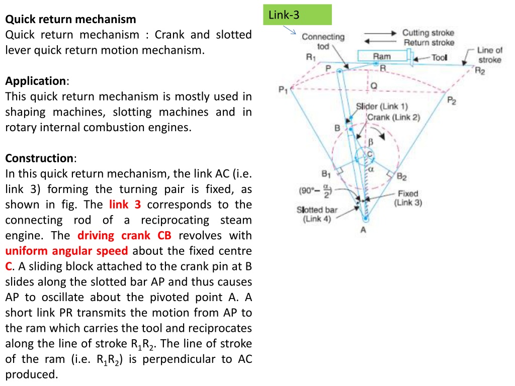
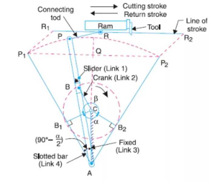
Link-3 Quick return mechanism Quick return mechanism : Crank and slotted lever quick return motion mechanism. Application: This quick return mechanism is mostly used in shaping machines, slotting machines and in rotary internal combustion engines. Construction: In this quick return mechanism, the link AC (i.e. link 3) forming the turning pair is fixed, as shown in fig. The link 3 corresponds to the connecting rod of a reciprocating steam engine. The driving crank CB revolves with uniform angular speed about the fixed centre C. A sliding block attached to the crank pin at B slides along the slotted bar AP and thus causes AP to oscillate about the pivoted point A. A short link PR transmits the motion from AP to the ram which carries the tool and reciprocates along the line of stroke R1R2. The line of stroke of the ram (i.e. R1R2) is perpendicular to AC produced.
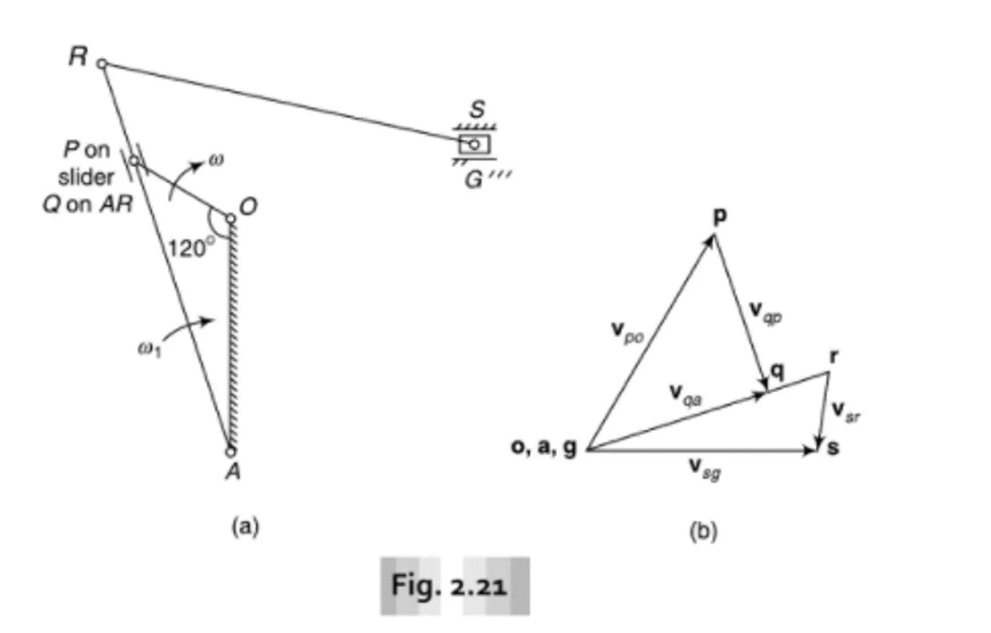
Velocity analysis of quick return mechanism VP Velocity point P: VP = op x OP Direction: Perpendicular to OP 900
Velocity component of point P perpendicular to AR VP VP 900 Velocity component of point P parallel to AR Velocity component of point P perpendicular to AR = Velocity of point Q ( point Q lie on link AR) (Point P and point Q are called as coincident point)
VQ = AR x AQ (AQ=AP) VR VP VR = AR x AR VQ 900 VS 900 VS/R
15 16 16 24 24 2 6 1 34 = infinifity 45 26 2 6 46 46 23 24 (6) 56 (2) 13 12 34 = infinifity (1) 12 13 14 15 16 23 24 25 26 34 35 36 45 46 56 (4) 13 13 14 2 1 4 2 5 4 2 6 4 1 2 3 4 5 6
Q. What is position of crank OP for which velocity of slider S is 0? Ans: If OP is perpendicular to link AR. There is two value of angular position of crank for which OP is perpendicular to AR R R S VS = 0 VS = 0 900 900
Q. What is position of crank OP for which velocity of slider S is 0? Ans: If OP is perpendicular to link AR. There is two value of angular position of crank for which OP is perpendicular to AR RS = 0 RS = 0 P P AR = 0 AR = 0
References: https://www.mechdiploma.com/draw-labeled- sketch-quick-return-mechanism-shaper-and- explain-its-working
45 56 23 OA = link-1 OP = link-2 12 Slider = link-3 AR = link-4 RS = link-5 Slider S = link-6 14
