Enhancing Network Performance with RoCE Technology


R
e
m
o
t
e
D
i
r
e
c
t
M
e
m
o
r
y
A
c
c
e
s
s
(
R
D
M
A
)
B
e
n
e
f
i
t
s
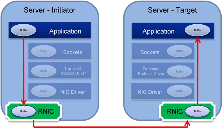
•
Hardware based transport stack
•
Provides low latency, high throughput, low CPU usage.
•
Offloads CPU network processing (OS TCP/IP stack)
•
Avoids data copy between user space and kernel space
•
CPU is utilized for computation operations in high-performance computing applications.
•
High network throughput in storage applications.
•
Low latency in real time applications.
TCP/IP
RDMA
RoCEv2 Packet Format
ECN field in IP header is used to mark
congestion (same as used for TCP)
R
o
C
E
–
R
D
M
A
O
v
e
r
C
o
n
v
e
r
g
e
d
E
t
h
e
r
n
e
t
Resilient RoCE Feature Progression
o
Software & Firmware based implementation of congestion control
o
Hardware support to catch ECN-marks and CNPs
o
Hardware-based congestion control
o
Hardware acceleration
to
support loss handling events
o
Hardware-based packet retransmission
o
Selective-Repeat
based transport control
O
p
t
i
m
i
z
i
n
g
P
e
r
f
o
r
m
a
n
c
e
W
i
t
h
N
e
t
w
o
r
k
Q
o
S
1.
High priority traffic class separation of CNPs (congestion notification
packets)
•
Fast propagation over the network. Bypassing congested queues.
2.
RoCE traffic priority isolation from other traffic (eg. background TCP,
UDP)
•
Avoid co-existence problems with non-controlled (or differently controlled)
traffic
3.
Flow Control (lossless network)
•
Better to pause packets than drop packets
R
o
C
E
C
C
(
D
C
Q
C
N
)
C
o
n
v
e
r
g
e
n
c
e
A
n
a
l
y
s
i
s
•
Assume N synchronous flows in congestion point draining to one port. Initial flow rate is link rate (eg. 100Gbps).
•
Rate of each flow needs to be reduced to link rate/N. So the total sum of flow rates will be equal to link rate.
•
Every rate reduction event, throttles the flow rate to half of previous rate. new rate = 0.5 * old rate.
•
Hence, need log2(N) reduction events in order to converge.
•
The first reduction event arrives after first CNP arrives (RTT since start)
•
Following reduction events occur in periods configured by rate_reduce_period parameter.
•
This is configurable parameter of DCQCN in the NIC
•
Hence, convergence time = RTT + log(N)*(rate_reduce_period-1)
•
Example:
•
network propagation time = 9 us (estimated, including links and switches)
•
NIC response time = 1 us
•
Switch queue delay = ECN mark threshold / link_rate
= 150KB (assuming switch configured to mark packets at 150KB) / 12.5GBps (= 100Gbps) = 12us
•
RTT = network propagation time + NIC response time + queue delay = 9us + 1us + 12us = 22us
•
Assume: number of flows N = 1024. All links are 100Gbps. Traffic arrives from 16 ports, draining to one port.
•
Time to converge = 22us + log2(1024)*4 us = 62us.
•
Buffer needed
= link rate * (num. incoming ports-1) * time to converge
= 100Gbps* 15 ports * 62us = (100/8)*10^9* 15 * 62*10^(-6) =
11,625 KB.
L
o
s
s
l
e
s
s
C
o
n
f
i
g
u
r
a
t
i
o
n
Enable ECN and PFC in all switch and NIC
•
NIC receive (Rx) congestion may occur
1.
NIC cache misses
2.
PCI bottleneck
•
Switch congestion may occur
•
Many to one communication
•
PFC may spread congestion to other switches
•
PFC may spread congestion to NIC transmit(Tx) side
•
PCIe congestion control
•
Use and optimize ECN to avoid the PFC
•
Buffer optimization in en-gress port
•
Faster ECN mark in switch and faster response for CNP in NIC
PFC + ECN
PFC + ECN
PFC + ECN
S
e
m
i
-
l
o
s
s
l
e
s
s
C
o
n
f
i
g
u
r
a
t
i
o
n
Address The Problem In Lossless:
•
NIC receive (Rx) congestion may occur
•
NIC cache misses
•
PCI bottleneck
•
PFC for NIC Congestion
•
NIC Rx congestion is propagated to the switch
•
Switch buffer absorbs the backpressure, congestion marked
with ECN
•
PFC may spread congestion to other switches
•
Semi-Lossless network solves NIC congestion and
prevents congestion spreading
•
NIC to switch: Uni-directional PFC
•
Switch to switch: no PFC
L
o
s
s
y
-
1
C
o
n
f
i
g
u
r
a
t
i
o
n
No PFC, End to End ECN only:
•
No PFC spread
•
Packet drop may happen
•
Selective Repeat
•
Optimize ECN
•
Buffer optimization in en-gress port
•
Fast Congestion Notification
o
Packets marked as they leave queue
o
Reduces average queue depth
•
Faster CNP creation in NIC receive
•
Give the highest priority for CNP
•
Faster reaction for CNP in NIC transmit
No PFC, ECN Only
No PFC, ECN Only
No PFC, ECN Only
L
o
s
s
y
-
2
C
o
n
f
i
g
u
r
a
t
i
o
n
No PFC, No ECN
•
No PFC spread
•
Packet drop may happen
•
Selective Repeat
•
Packet drop trigger the reaction in the NIC transmit(Tx)
No PFC, No ECN
No PFC, No ECN
No PFC, No ECN
T
r
a
f
f
i
c
C
l
a
s
s
i
f
i
c
a
t
i
o
n
•
Required for setting:
•
QoS
•
Buffer management
•
PFC
•
Indicated by
•
DSCP (Differentiated Service Code Point, layer 3, in IP header).
•
PCP (Priority Code Point, layer2, in Vlan tag).
•
DSCP is the recommended method.
•
Set by
trust
command.
R
e
c
o
m
m
e
n
d
e
d
C
l
a
s
s
i
f
i
c
a
t
i
o
n
•
RoCE
•
Lossless / lossy
•
Uses DSCP 26 / PCP 3. Mapped to switch-priority 3
•
CNP
•
Lossy
•
Uses DSCP 48 / PCP 6. Mapped to switch-priority 6
•
Strict scheduling (highest priority)
•
Other traffic
•
Untouched (default)
•
Recommended to enable ECN for TCP as well
H
o
s
t
I
n
g
r
e
s
s
Q
o
S
M
o
d
e
l
•
Packets are classified into internal priority according to the packets priority:
•
PCP – Priority Code Point, layer 2 priority, located in the VLAN tag
•
DSCP – Differentiated Service Code Point, layer 3 priority, located in the IP header
•
Internal priorities are mapped to buffer(s)
•
Buffer and priorities can be configured as
•
lossy – when buffer is full, packets will be dropped
•
Lossless – when buffer is almost full, a pause will be sent to the transmitter to stop transmission
•
Can be either based on global pause or priority flow control (PFC)
•
In egress direction the device conform the packet priority
•
Ethernet
•
Trust PCP – according to WQE
•
Trust DSCP – according to TCLASS
•
UD
•
Trust PCP – according to WQE
•
Trust DSCP – according to TCLASS
•
RC
•
Trust PCP – according to QP’s eth prio
•
Trust DSCP – according to QP’s TCLASS
S
w
i
t
c
h
P
r
i
o
r
i
t
y
C
l
a
s
s
i
f
i
c
a
t
i
o
n
DSCP (IP header) (0-
63)
P
C
P
(
V
L
A
N
h
e
a
d
e
r
)
(
0
-
7
)
S
w
i
t
c
h
-
p
r
i
o
r
i
t
y
(
0
-
7
)
Priority Group (PG)
(Ingress Buffer)
(0-7)
Traffic Class (TC)
(Egress Queue)
(0-7)
Default mapping:
All to 0
Default mapping:
3 MSB = priority
Default mapping:
PCP = priority
Default mapping:
priority = traffic
class
Used for:
ETS Configuration: WRR, strict
ECN: min/max threshold
Shared buffer: alpha, reserved
Used for:
Flow Control: xoff, xon
Shared buffer: alpha, reserved
S
t
a
n
d
a
r
d
R
o
C
E
H
a
n
d
l
i
n
g
P
a
c
k
e
t
D
r
o
p
s
•
Congestion control doesn’t guarantee packet
drops avoidance.
•
RoCE uses InfiniBand transport semantics.
•
InfiniBand transport is reliable!
•
Packets are marked with sequence numbers (PSN)
•
On first packet arrived out of order, responder
sends out-of-sequence (OOS) NACK.
•
OOS NACK includes the PSN of the expected
packet.
•
Requestor handles OOS NACK by retransmitting all
packets beginning from the expected PSN.
S
e
l
e
c
t
i
v
e
R
e
p
e
a
t
Loss of a request:
•
Upon receiving an OOS request the responder:
•
Send immediate OOS NAK for the first one
•
Store it using existing OOO placement
mechanisms
•
Upon receiving OOS NAK the requestor:
•
Transmit only the NAKed packet, and wait for
following acks
Loss of a response:
•
Upon receiving an OOS response packet:
•
Store it using OOS placement mechanisms
•
Issue a new read request
for the missing ranges
•
Then continue sending new requests
Loss of a request
Loss of a response
I
d
e
a
l
D
a
t
a
T
r
a
f
f
i
c
•
Slow & constant transmission is better
than retransmission
•
Use ECN to tune the speed per QP or flow
•
PFC may help to reduce the packet drop
•
Credit based flow control per hop
S
m
a
r
t
N
I
C
A
p
p
l
i
c
a
t
i
o
n
E
x
a
m
p
l
e
(
N
V
M
e
E
m
u
l
a
t
o
r
)
Hypervisor
Cloud Storage
Bare-Metal
Cloud Storage
SmartNIC
Cloud Storage
SmartNIC
Bare-Metal Cloud
Storage
Guest
VM
Hypervisor
Guest
VM
Storage
Virtualization
Driver
NVMe
Emulation Adapter
NVMe
Emulation Adapter
Bare-Metal Cloud Storage
Virtualized Cloud Storage
OS Agnostic, Near-local performance, Secured, Any Ethernet wire protocol
Physical
NVMe SSD
Drive
Bare Metal
x86 Server
Storage
Virtualization
Driver
Physical
NVMe SSD
Drive
Bare Metal
x86 Server
Storage
Virtualization
Driver
Remote Target
Storage
Two solutions in one
Emulated NVMe PCIe device
•
Emulating a local physical
NVMe SSD drive to the Host
•
Emulating via SR-IOV multiple
NVMe SSD drives to VMs
NIC
•
Up to line rate throughput
•
Low latency (end-to-end)
•
Native RDMA and RoCE
•
Integrated hardware offloads
Thanks
Remote Direct Memory Access (RDMA) benefits, RoCEv2 packet format, resilient RoCE feature progression, optimizing network performance with QoS, and RoCE congestion control convergence analysis are discussed in this proposal. RoCE technology offers low latency, high throughput, and efficient CPU usage, making it ideal for high-performance computing and storage applications. Hardware-based implementations improve congestion control, loss handling, and packet retransmission, ensuring reliable and resilient network operations. Quality of Service (QoS) techniques help optimize performance by prioritizing traffic class separation and flow control for RoCE traffic. Understanding RoCE technology advancements can significantly enhance network capabilities.

Download Presentation

Please find below an Image/Link to download the presentation.
The content on the website is provided AS IS for your information and personal use only. It may not be sold, licensed, or shared on other websites without obtaining consent from the author. Download presentation by click this link. If you encounter any issues during the download, it is possible that the publisher has removed the file from their server.
E N D
Presentation Transcript
RoCE Network Proposal Qingchun Song Qingchun@mellanox.com
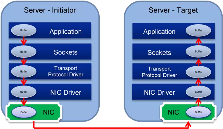
Remote Direct Memory Access (RDMA) Benefits Remote Direct Memory Access (RDMA) Benefits Hardware based transport stack Provides low latency, high throughput, low CPU usage. Offloads CPU network processing (OS TCP/IP stack) Avoids data copy between user space and kernel space CPU is utilized for computation operations in high-performance computing applications. High network throughput in storage applications. Low latency in real time applications. Server - Initiator Server - Target Server - Initiator Server - Target Application Application Application Application Buffer Buffer Buffer Buffer Sockets Sockets Sockets Sockets Buffer Buffer Buffer Buffer Transport Protocol Driver Transport Protocol Driver Transport Protocol Driver Transport Protocol Driver Buffer Buffer Buffer Buffer NIC Driver NIC Driver NIC Driver NIC Driver Buffer Buffer Buffer Buffer RNIC RNIC NIC NIC Buffer Buffer Buffer Buffer RDMA TCP/IP
RoCEv2 Packet Format RoCE RoCE RDMA Over Converged Ethernet RDMA Over Converged Ethernet ECN field in IP header is used to mark congestion (same as used for TCP) Layer3 IP TOS (RF791) DSCP (RFC 2474) IP header header Throu ghput Reliabi lity Precedence Spare TOS: delay Class selector 0b000 ECN ECN DSCP: 3 bits 1 Byte
Resilient RoCE Feature Progression o Software & Firmware based implementation of congestion control o Hardware support to catch ECN-marks and CNPs o Hardware-based congestion control o Hardware acceleration to support loss handling events o Hardware-based packet retransmission o Selective-Repeat based transport control
Optimizing Performance With Network Optimizing Performance With Network QoS QoS 1. High priority traffic class separation of CNPs (congestion notification packets) Fast propagation over the network. Bypassing congested queues. 2. RoCE traffic priority isolation from other traffic (eg. background TCP, UDP) Avoid co-existence problems with non-controlled (or differently controlled) traffic 3. Flow Control (lossless network) Better to pause packets than drop packets
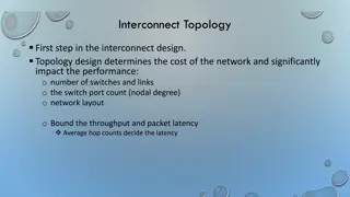
RoCE RoCE CC (DCQCN) Convergence Analysis CC (DCQCN) Convergence Analysis Assume N synchronous flows in congestion point draining to one port. Initial flow rate is link rate (eg. 100Gbps). Rate of each flow needs to be reduced to link rate/N. So the total sum of flow rates will be equal to link rate. Every rate reduction event, throttles the flow rate to half of previous rate. new rate = 0.5 * old rate. Hence, need log2(N) reduction events in order to converge. The first reduction event arrives after first CNP arrives (RTT since start) Following reduction events occur in periods configured by rate_reduce_period parameter. This is configurable parameter of DCQCN in the NIC Hence, convergence time = RTT + log(N)*(rate_reduce_period-1) Example: network propagation time = 9 us (estimated, including links and switches) NIC response time = 1 us Switch queue delay = ECN mark threshold / link_rate = 150KB (assuming switch configured to mark packets at 150KB) / 12.5GBps (= 100Gbps) = 12us RTT = network propagation time + NIC response time + queue delay = 9us + 1us + 12us = 22us Assume: number of flows N = 1024. All links are 100Gbps. Traffic arrives from 16 ports, draining to one port. Time to converge = 22us + log2(1024)*4 us = 62us. Buffer needed = link rate * (num. incoming ports-1) * time to converge = 100Gbps* 15 ports * 62us = (100/8)*10^9* 15 * 62*10^(-6) = 11,625 KB.
Lossless Configuration Lossless Configuration Enable ECN and PFC in all switch and NIC NIC receive (Rx) congestion may occur 1. NIC cache misses 2. PCI bottleneck Switch congestion may occur Many to one communication PFC may spread congestion to other switches PFC may spread congestion to NIC transmit(Tx) side PCIe congestion control Use and optimize ECN to avoid the PFC Buffer optimization in en-gress port Faster ECN mark in switch and faster response for CNP in NIC PFC + ECN PFC + ECN PFC + ECN PFC + ECN switch NIC
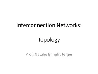
Semi Semi- -lossless Configuration lossless Configuration Address The Problem In Lossless: NIC receive (Rx) congestion may occur NIC cache misses PCI bottleneck PFC for NIC Congestion NIC Rx congestion is propagated to the switch Switch buffer absorbs the backpressure, congestion marked with ECN PFC may spread congestion to other switches Semi-Lossless network solves NIC congestion and prevents congestion spreading NIC to switch: Uni-directional PFC Switch to switch: no PFC No PFC No PFC PFC from NIC to switch No PFC from switch to NIC PFC from NIC to switch No PFC from switch to NIC switch NIC
Lossy Lossy- -1 Configuration 1 Configuration No PFC, End to End ECN only: No PFC spread Packet drop may happen Selective Repeat Optimize ECN Buffer optimization in en-gress port Fast Congestion Notification o Packets marked as they leave queue o Reduces average queue depth Faster CNP creation in NIC receive Give the highest priority for CNP Faster reaction for CNP in NIC transmit No PFC, ECN Only No PFC, ECN Only No PFC, ECN Only No PFC, ECN Only switch NIC
Lossy Lossy- -2 Configuration 2 Configuration No PFC, No ECN No PFC spread Packet drop may happen Selective Repeat Packet drop trigger the reaction in the NIC transmit(Tx) No PFC, No ECN No PFC, No ECN No PFC, No ECN No PFC, No ECN switch NIC
Traffic Classification Traffic Classification Layer2 Layer3 D. MAC S. VLAD TPID PCP .1Q VLAN CFI & VID Ether Type IP TOS (RF791) DSCP (RFC 2474) IP payload CRC MAC header header delayThrou Reliabi lity Priority Precedence Spare TOS: ghput Class selector 0b000 ECN DSCP: 3 bits Required for setting: QoS Buffer management PFC Indicated by DSCP (Differentiated Service Code Point, layer 3, in IP header). PCP (Priority Code Point, layer2, in Vlan tag). DSCP is the recommended method. Set by trust command. 3 bits 1 Byte
Recommended Classification Recommended Classification RoCE Lossless / lossy Uses DSCP 26 / PCP 3. Mapped to switch-priority 3 CNP Lossy Uses DSCP 48 / PCP 6. Mapped to switch-priority 6 Strict scheduling (highest priority) Other traffic Untouched (default) Recommended to enable ECN for TCP as well
Host Ingress QoS Model Host Ingress QoS Model Packets are classified into internal priority according to the packets priority: PCP Priority Code Point, layer 2 priority, located in the VLAN tag DSCP Differentiated Service Code Point, layer 3 priority, located in the IP header Internal priorities are mapped to buffer(s) Buffer and priorities can be configured as lossy when buffer is full, packets will be dropped Lossless when buffer is almost full, a pause will be sent to the transmitter to stop transmission Can be either based on global pause or priority flow control (PFC) In egress direction the device conform the packet priority Ethernet Trust PCP according to WQE Trust DSCP according to TCLASS UD Trust PCP according to WQE Trust DSCP according to TCLASS RC Trust PCP according to QP s eth prio Trust DSCP according to QP s TCLASS
Switch Priority Classification Switch Priority Classification Priority Group (PG) Default mapping: All to 0 Default mapping: 3 MSB = priority Used for: (Ingress Buffer) DSCP (IP header) (0- Flow Control: xoff, xon Shared buffer: alpha, reserved (0-7) 63) Switch-priority (0-7) Used for: PCP (VLAN header) Traffic Class (TC) ETS Configuration: WRR, strict ECN: min/max threshold Shared buffer: alpha, reserved (0-7) (Egress Queue) (0-7) Default mapping: PCP = priority Default mapping: priority = traffic class
Standard Standard RoCE RoCE Handling Packet Drops Handling Packet Drops Requestor Responder Congestion control doesn t guarantee packet drops avoidance. RoCE uses InfiniBand transport semantics. InfiniBand transport is reliable! Packets are marked with sequence numbers (PSN) On first packet arrived out of order, responder sends out-of-sequence (OOS) NACK. OOS NACK includes the PSN of the expected packet. Requestor handles OOS NACK by retransmitting all packets beginning from the expected PSN. Retransmission
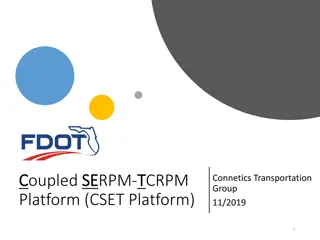
Selective Repeat Selective Repeat Loss of a request: Upon receiving an OOS request the responder: Send immediate OOS NAK for the first one Store it using existing OOO placement mechanisms Upon receiving OOS NAK the requestor: Transmit only the NAKed packet, and wait for following acks Loss of a response Loss of a request Requestor Responder Requestor Responder 1 2 3 4 5 6 7 Large read 1 X Med response lost X OOS NAK 3 3 Loss of a response: Upon receiving an OOS response packet: Store it using OOS placement mechanisms Issue a new read request for the missing ranges Then continue sending new requests Med read 1 Large read 2 Ack 7 8 9 10
I Ideal Data Traffic deal Data Traffic Slow & constant transmission is better than retransmission Use ECN to tune the speed per QP or flow PFC may help to reduce the packet drop Credit based flow control per hop
SmartNIC SmartNIC Application Example ( Application Example (NVMe NVMe Emulator) Emulator) Bare-Metal Cloud Storage Virtualized Cloud Storage SmartNIC Bare-Metal Cloud Storage Bare-Metal Cloud Storage Hypervisor Cloud Storage SmartNIC Cloud Storage Two solutions in one Emulated NVMe PCIe device Emulating a local physical NVMe SSD drive to the Host Emulating via SR-IOV multiple NVMe SSD drives to VMs Guest VM Guest VM Guest VM Guest VM Bare Metal x86 Server Bare Metal x86 Server Storage Virtualization Driver NIC Hypervisor Hypervisor Up to line rate throughput Low latency (end-to-end) Native RDMA and RoCE Integrated hardware offloads Storage Virtualization Driver Physical NVMe SSD Drive Physical NVMe SSD Drive Storage Virtualization Driver Storage Virtualization Driver Network Adapter NVMe Emulation Adapter Network Adapter NVMe Emulation Adapter Remote Target Storage OS Agnostic, Near-local performance, Secured, Any Ethernet wire protocol

 Benefits")