Steel Structural Design for Basketball Court Cover Project

This project involves designing a steel structure to cover a basketball court with specific dimensions using various codes and standards. The design includes considerations for gravity and lateral loads, such as dead load and live load. The overall aim is to create a cost-effective and efficient structure with the use of different structural systems and bracing configurations.
- Steel Structure Design
- Basketball Court Cover
- Codes and Standards
- Structural Analysis
- Load Calculation

Download Presentation

Please find below an Image/Link to download the presentation.
The content on the website is provided AS IS for your information and personal use only. It may not be sold, licensed, or shared on other websites without obtaining consent from the author. Download presentation by click this link. If you encounter any issues during the download, it is possible that the publisher has removed the file from their server.
E N D
Presentation Transcript
Steel Structural Design Supervisor : Dr. Sameer Al- helo Prepared by: Abdallah Sami Abdallah Ahmad Saadi Moad Al-Masri Oday Melhem
Out line: Introduction Codes Loads Analysis Checks Design Results and Conclusion
Introduction The present project addresses the cover of a basketball court. The play area has the dimensions of 15mx28m while the cover is 20mx 39m. The Proposed structure is to be made of steel elements and covered by poly carbon transparent sheets. The structure is a standalone structure which should have a minimum height of 7 meters. The intension is to use different sections, 2 different structural systems and different bracing configuration. A feasibility study follows to minimize cost. This is achieved by minimizing the resulting design weight. The design exercise includes the design of concrete spread footings, and all relevant connections.
Codes The structure was designed using codes of practice and specifications that control the design process and variables. The following codes and standards were used in this project: 1- IBC: International Building Code. 2- ACI: American Concrete Institute provision for reinforced concrete structural design. 3- Jordanian code. 4- UBC-97 code.
Loads There are two types of loads based on direction, gravity and lateral loads.
Gravity loads: Dead load: The weight of materials of construction incorporated into the building, including but not limited to walls, floors, roofs, ceilings, stairways, built-in partitions, finishes, cladding and other similarly incorporated architectural and structural items, and the weight of fixed service equipment, such as cranes, plumbing stacks and risers, electrical feeders, heating, ventilating and air-conditioning systems and automatic sprinkler systems.
live load: A load produced by the use and occupancy of the building or other structure that does not include construction or environmental loads such as wind load, snow load, rain load, earthquake load, flood load or dead load.
Snow load: Loads resulting from the accumulation of snow on the roof of the building vary widely according to the geographical location (climate) and height above the mean sea level (MSL). Snow load are computed according to the Jordanian code for snow loads.
Rain load: Each portion of a roof shall be designed to sustain the load of rainwater that will accumulate on it if the primary drainage system for that portion is blocked plus the uniform load caused by water that rises above the inlet of the secondary drainage system at its design flow.
Lateral loads: Wind load: Wind load is produced due to change in momentum of an air striking the surface of a building.
Seismic loads: There are two principles to design seismic load: The equivalent static force procedure. Dynamic analysis. The equivalent static force method depend in equation F=ma , this formula depends on replacing of the seismic force by equivalent force called shear base force.
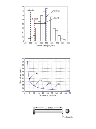
Analysis Determination of load of those two models: dead load : Each frame in case 1 has weight equal to 27.9 KN equal 2.84 ton. Each frame in case 2 has steel weight equal to 17.42KN equal 1.77 ton and concrete weight equal 126 KN equal 12.84 ton.
Snow load 4 100 ? = S: snow load (kg/?2) h: height above (MSL) which know for Ramallah = 850 m (Jordanian code). The snow load in Ramallah equal 112.5 kg/??.
Rain load: R = 0.0098(ds+ dh) where: dh= Additional depth of water on the undeflected roof above the inlet of secondary drainage system at its design flow (i.e., the hydraulic head), in inches (mm). ds= Depth of water on the undeflected roof up to the inlet of secondary drainage system when the primary drainage system is blocked (i.e., the static head), in inches (mm). R = Rain load on the undeflected roof, in psf (kN/m2). When the phrase "undeflected roof" is used, deflections from loads (including dead loads) shall not be considered when determining the amount of rain on the roof. (ds+dh) know for Nablus about 100 mm The rain load in Nablus equal 0.98 kN/??. The rain load is vary small as a result neglect it.
Wind load: Assumption: Velocity = 100 km/hr =27.78 m/s. Exposure B. I=1. K zt=1. Then qz=402Kz H= 9 m H less than 18m high of structure. And less than 20 m width of structure. Then the the structure is low-raised. Inl lee ward Cp=-0.5 And Kh= 0.72 Then P= 123.012 N/m2
In side wall Cp=-0.7 P=202.608 N/m2 In wend ward Cp=+0.8 P=196.819 N/m2 Pmin=500/1.3 x Cp For lee ward Pmin =192.3 N/m2 For side wall Pmin = 269.23 N/m2 For wind ward Pmin =307.7 N/m2 Because Pmin for all side largest than P , use Pmin for all side.
Sismic load: Assumption: The structure located in Nablus city Zone 2B then Z=0.2 The type of soil is rock SB R=8 Calculation: Cv=0.2 Ct=0.035 Then T=2.05 W=22.4 KN V for steel column structure=0.3 W=136.2 KN V for concrete column structure=1.66
Checks Compatibility Check Check the model using the animation tool in SAP. Case 1 Case 2
Check Equilibrium This check will done for each load pattern separately, here we will check Live Load pattern: For live load : (3x2+6x7)=48 KN , base reaction from live load =48KN, OK. For snow load : (5.63x2+11.25x7)=90.01KN base reaction from snow load =90KN,OK.
Stress-Strain Check Layout ???? ? ? ?? ? = 8 20 20 8 287 ??????740 717.5 ?? ???????? 296 2.5 =
Check for Deflection Case 1 Case 2
Design Case 1 Case 2
Footing design For case 1: -qall= 294.3KN/m2 ??= 127.2 ?? ?? ?????????? ??=127.2 0.4 87.7 294.3= 0.29 ? ?????????? 0.4 ? 0.4 ? ? = = = 795 ??/? Check punching shear ?? = ?? qu c1 + d)(c2 + d) = 635.4 ?? 1 3 1 2 +?? ? ?? = 0.75 ????? ? 12 ?? 2 ?? 1 6 1 +
Vu=?? ?? =?(????) ?(? ???)?? ? ? ?????? > 2 ?? = 0.75 1 ???????? =0.60 0.20= 3 6 b d 28 = 753.7?? ????? ?? > ? ?????? ?? Check for punching moment )2=181.29 0.352 ?? =?? ? ?(? ?2 = 3.3 ?? 2 2 2 1 2.6 106 11.10 1000 220 28 ? =0.85 28 = 2 10 3 1 420 ?? = 29 ?? ????? = 770 ?? ?????? ??? ????? = 770 ?? ?????? ??? 5 14/1? ????? ?? < ?????
For case 2 -qall= 294.3KN/m2 ??= 273 ?? ?? =210.5 294.3= 0.72 ? ??=273 0.8 = 426.5 ??/? ?????????? 0.8 ? 0.8 ? ? = ?????????? -d=0.4m Check punching shear ?? = ?? qu c1 + d)(c2 + d) = 580 ?? 1 3 1 2 +?? ? ?? = 0.75 ????? ? 12 ?? 2 ?? 1 6 1 +
Vu=?? ???????? =0.60 ?(????) ?(? ???)?? ? ? ?????? > 2 ?? = 0.20= 3 ?? = 0.75 1 6 b d 28 = 2095.43?? ?????? ?? ????? ?? > ? Check for punching moment 2)2=181.29 0.352 ?? =?? ? ?(? ?2 = 1.706 ?? 2 2 1 2.6 106 11.10 ? =0.85 28 1000 220 28= 2 10 3 1 420 ?? = 640 ?? ????? = 432 ?? ?????? ??? ?? = 640 ?? ?????? ??? 5 14/1? ????? ?? > ?????
Design of weld connection E70XX weld is used Fu = 482 MPa. Gust plate thickness 10mm ??= 296.5 ?? ??= ?? ?????? ?? = 341.7 ?? 296.5 = 0.75 ?? 0.60 482 4 Use lw= 342mm.
Tension member W 12x22 ??= 275 ?? ??????? =0.90 4190 250 ?????????? =0.75 4190 400 0.9 = 942.75 ?? 1000 = 1131 ?? 1000 ?????? ????? ??????? ????? ?? 1131 > 942.75 > ??
compression member w10x22 PU= 301.4 KN =1 2.5 1000 108.5 KL r = 23.04 Fcr= 295 MPa (From tables of AISC code) Ag= 4910 mm ??= 295 4910 1000= 1448.45 ?? > 301.4 ?????? ??
Results and conclusion 1- Comparing between two structural models weight and price. Case 1 has weight equal to 27.9KN equal 2.84 ton Price of one ton equal 3000 NIS Then the frame price equal 8535 NIS And structure approximately price equal 110955 NIS Case 2 has weight equal to 17.42KN equal 1.77 ton Price of one ton equal 3000 NIS Then the frame price equal 5328 NIS And steel structure price equal 69264 NIS And the price of concrete equal to 19656 NIS All price equal 88920 NIS .
2- Base shear reaction The base shear reaction for case 1 equal to 0.3 The base shear reaction for case 2 equal to 1.66 The deferent between base shear reaction is product from deferent in weight . 3- Shown in previous results the deferent in design of section size, this size is affected by type of material and size of columns. 4- Shown in previous checks the deferent in deflection values between two cases , case 1 has more deflection.