Verilog Adder Examples & Typical IC Design Flow
This comprehensive content delves into Verilog adder examples, typical IC design flow, physical design considerations, and examples of OpenGL ES GPU and ARM hypervisor applications. It covers the fundamentals of digital logic with Verilog design, hardware description language, FPGA prototyping, physical layout checks, and more. Explore the design conception process, post-layout simulations, and detailed insights into the physical design stage. Additionally, examples of cutting-edge technologies like OpenGL ES 1.0 GPU and ARM hypervisor implementations in Taiwan are discussed.

Download Presentation

Please find below an Image/Link to download the presentation.
The content on the website is provided AS IS for your information and personal use only. It may not be sold, licensed, or shared on other websites without obtaining consent from the author. Download presentation by click this link. If you encounter any issues during the download, it is possible that the publisher has removed the file from their server.
E N D
Presentation Transcript
Supplement on Verilog adder examples Based on Fundamentals of Digital Logic with Verilog Design By Brown/Vranesic 3rd. Chung-Ho Chen 1
Typical IC Design Flow Design conception DESIGN ENTRY HDL: Hardware Description Language Schematic capture Verilog Synthesis FPGA prototyping Functional simulation No Design correct? Yes Physical design Post-layout simulation Timing simulation No Timing requirements met? Tape-out 2
More details on physical design DRC: design rule check: ensures that the physical layout of a particular chip satisfies a series of recommended parameters called Design Rules. LVS: Layout Versus Schematic (LVS) ERC: electrical rule check .. 3
Example: OpenGL ES 1.0 GPU; first in Taiwan using ESL Full System Verification, completed in 2009 Reference implementation Software development Full System Simulation ARM System Emulator ARM System Emulator ( (ARM Versatile baseboard ARM Versatile baseboard ) ) ARM ARM926 926E E, , ARM ARM1136 1136 or Cortex PL PL190 190 Vectored Interrupt Controller Vectored Interrupt Controller Four PL Four PL011 011 UARTs SMC SMC 91 91c c111 111 Ethernet adapter Ethernet adapter PL PL050 050 KMI with PS KMI with PS/ /2 2 keyboard and mouse ... ... or Cortex- -A A8 8 CPU CPU OpenGL ES Application OpenGL ES Application Qemu Qemu ( (C C, , C C++) ++) UARTs keyboard and mouse. . AHB Interface Virtual Hardware AHB Interface Virtual Hardware Khronos OpenGL ES 1.x SDK for POWERVR MBX Qemu Qemu- -SystemC Wrapper SystemC Wrapper OpenGL ES API Socket Interface Socket Interface ( (Client Client) ) Socket Interface Socket Interface ( (Server Server) ) Pure C/C++ simulation OpenGL32.dll Qemu Qemu- -SystemC Wrapper SystemC Wrapper AHB AHB Master Master M M Graphics Graphics Hardware Hardware M M Interrupt Interrupt Controller Controller CoWare CoWare SystemC, , HDL P P P P ( (SystemC HDL) ) S S The Back-End GPU Simulator ATI/NVIDIA/...etc. AHB AHB S S SDRAM SDRAM Module Module Frame buffer Frame buffer CHECK! CHECK! Debugging files Statistics files
Example: ARM Example: ARM Hypervior first in Taiwan, 2012 first in Taiwan, 2012 Hypervior and its ESL Platform, and its ESL Platform, SystemC functional model VM 0 VM n TLM 2.0 Bus VM support, allow multiple VM Linux OSes booting on platform of one core system CASL Hypervisor ARM v7a- vm TLM 2.0 Bus System Controller Interrupt Controller Memory Timer UART
Example: CASLab System Simulator/ISS/Core Full access to CASLab students: CASLab Axx v7a-VM Cortex A15 1 ISA Axx v4 Axx v6 Axx v6k Axx v7a Axx 11 MP 4 Cortex A8 1 CPU Axx 926 Axx 11 Core No. 1 1 RTL/ Functional OOO Type Functional Functional Functional Functional Versatile PB RealView EB RealView EB RealView PB RealView PB Board Linux Booting Yes Yes Yes Yes Yes VT No No No No Yes Support
Example: NCKUEE Dual-Core Processors, First in Taiwan s University, 2013
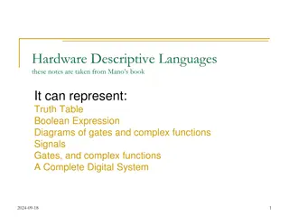
Describe a circuit in a form of module Gate Level: structural description and (u, ~s, x1); // without an explicit not ahead module mux (x1, x2, s, f); input x1, x2, s; output f; keyword not (si,s); and (u, si, x1); and (l, s, x2); or (f, u, l); endmodule output 8
Behavioral: logic equation module mux (x1, x2, s, f); input x1, x2, s; output f; Continuous assignment: f is re-evaluated whenever the right hand side signal changes. assign f = (~s & x1) | (s &x2); assign y = f | x2; No order for f and y, concurrent statement; assign: for nets (like wire) since nets can not hold values, so you need to assign the value continuously. endmodule 9
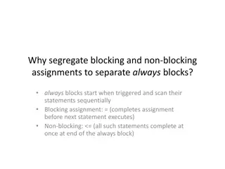
Behavioral: procedural statement The simulator registers this value until the always block is executed again. output reg f; module mux (x1, x2, s, f); input x1, x2, s; output f; reg f; always@(sensitivity list) always@(x1, x2, s) if (s == 0) Evaluated in the order given by the code; if first, then else. = blocking assignment (evaluated in order) f = x1; else f = x2; endmodule 10
Coding in 3 ways: Gate instantiation Continuous assignment (assign) Procedural statements (always) Blocking assignment = sequencing S = X + Y; // S[3:0] C = S[0]; // C takes the new value from X+Y. Non-blocking assignment <= S <= X + Y; C <= S[0]; // at simulation time ti, C takes the value of S[0] at simulation time ti-1 11
More compact procedural statement module mux (input x1, x2, s, output reg f); always@(x1, x2,s) if (s == 0) f = x1; else f = x2; endmodule 12
Hierarchical Verilog Code Hierarchical Verilog Code Top-level module module whole (X1, X2, A, B, C, D, E); Input X1, X2; output A, B, C, D, E; wire w0, w1; a b c d e A B C D E w0 X1 a c y1 b d y2 X2 w1 front U1 (X1, X2, w0, w1); back U2 (w0, w1, A, B, C, D, E); .. endmodule module front (a, b, c, d); Input a, b; output c, d; .. endmodule module back (y1, y2, a, b, c, d, e); Input y1, y2; output a, b, c, d, e; .. endmodule Internal (not output or input) uses wire. 13
Full Adder Full Adder U Using sing G Gates ates x i y i c i 00 01 11 10 module fulladd (Cin, x, y, s, Cout); input Cin, x, y; output s, Cout; 1 1 0 c i x i y i s i i c + 1 1 1 1 0 0 0 0 1 1 1 1 0 0 1 1 0 0 1 1 0 1 0 1 0 1 0 1 0 0 0 1 0 1 1 1 0 1 1 0 1 0 0 1 = s i x i y i c i x i y i module fulladd (Cin, x, y, s, Cout); input Cin, x, y; output s, Cout; c i 00 01 11 10 xor (s, x, y, Cin); and (a, x, y); and (b, x, Cin); and (c, y, Cin); or (Cout, a, b, c); 1 0 1 1 1 1 (a) Truth table = + + c i x i y i x i c i y i c i + 1 (b) Karnaugh maps xor (s, x, y, Cin); and (a, x, y), (b, x, Cin), //omit and (c, y, Cin); or (Cout, a, b, c); x i y i s i endmodule c i endmodule c i + 1 (c) Circuit 14
Full Adder Full Adder U Using sing F Functional unctional E Expression xpression x i y i c i 00 01 11 10 1 1 0 c i x i y i s i i c + 1 1 1 1 0 0 0 0 1 1 1 1 0 0 1 1 0 0 1 1 0 1 0 1 0 1 0 1 0 0 0 1 0 1 1 1 0 1 1 0 1 0 0 1 = s i x i y i c i module fulladd (Cin, x, y, s, Cout); input Cin, x, y; output s, Cout; assign s = x ^ y ^ Cin, Cout = (x & y) | (x & Cin) | (y & Cin); endmodule x i y i c i 00 01 11 10 1 0 1 1 1 1 (a) Truth table = + + c i 1 + x i y i x i c i y i c i (b) Karnaugh maps x i y i s i c i c i 1 + (c) Circuit 15
3 3- -bit Ripple Adders bit Ripple Adders module adder3 (c0, x2, x1, x0, y2, y1, y0, s2, s1, s0, carryout); input c0, x2, x1, x0, y2, y1, y0; output s2, s1, s0, carryout; fulladd b0 (c0, x0, y0, s0, c1); fulladd b1 (c1, x1, y1, s1, c2); fulladd b2 (c2, x2, y2, s2, carryout); endmodule Instantiate the fulladd module module fulladd (Cin, x, y, s, Cout); input Cin, x, y; output s, Cout; assign s = x ^ y ^ Cin, assign Cout = (x & y) | (x & Cin) | (y & Cin); endmodule 16
3 3- -bit Ripple Adders Using Vectored Signals bit Ripple Adders Using Vectored Signals Vectored signals used module adder3 (c0, x2, x1, x0, y2, y1, y0, s2, s1, s0, carryout); input c0, x2, x1, x0, y2, y1, y0; output s2, s1, s0, carryout; module adder3 (c0, X, Y, S, carryout); input c0; input [2:0] X, Y; output [2:0] S; output carryout; wire [2:1] C; fulladd b0 (c0, x0, y0, s0, c1); fulladd b1 (c1, x1, y1, s1, c2); fulladd b2 (c2, x2, y2, s2, carryout); endmodule fulladd b0 (c0, X[0], Y[0], S[0], C[1]); fulladd b1 (C[1], X[1], Y[1], S[1], C[2]); fulladd b2 (C[2], X[2], Y[2], S[2], carryout); module fulladd (Cin, x, y, s, Cout); input Cin, x, y; output s, Cout; endmodule assign s = x ^ y ^ Cin, assign Cout = (x & y) | (x & Cin) | (y & Cin); endmodule 17
n n- -bit Ripple Adders bit Ripple Adders module adderN (c0, X, Y, S, carryout); parameter n = 16; input c0; input [n-1:0] X, Y; output reg [n-1:0] S; output reg carryout; reg [n:0] C; integer k; always @(X, Y, c0) begin C[0] = c0; for (k = 0; k < n; k = k+1) begin 1: for: a procedural statement, must be inside a always block. for loop in Verilog specifies a different subcircuit in each iteration. for loop does not specify change that takes place in time during successive iterations as in a programming language. 2: Values inside a always block must retain their values until any change of signals in the sensitivity list. To hold on the values, use reg to keep them. There is no physical meaning of k in the circuit. It is used to tell the compiler that how many instances of the iteration are needed. S[k] = X[k] ^ Y[k] ^ C[k]; C[k+1] = (X[k] & Y[k]) | (X[k] & C[k]) | (Y[k] & C[k]); end carryout = C[n]; end endmodule 18
3 3- -bit to n bit to n- -bit transformation using bit transformation using generate generate module addern (c0, X, Y, S, carryout); parameter n = 16; input c0; input [n-1:0] X, Y; output [n-1:0] S; output carryout; wire [n:0] C; module adder3 (c0, X, Y, S, carryout); input c0; input [2:0] X, Y; output [2:0] S; output carryout; wire [2:1] C; Instantiate a submodule n times using generate fulladd b0 (c0, X[0], Y[0], S[0], C[1]); fulladd b1 (C[1], X[1], Y[1], S[1], C[2]); fulladd b2 (C[2], X[2], Y[2], S[2], carryout); genvar i; // to be used in generate assign C[0] = c0; assign carryout = C[n]; generate for (i = 0; i <= n-1; i = i+1) begin:adderbit fulladd b (C[i], X[i], Y[i], S[i], C[i+1]); end endgenerate endmodule endmodule Instance name produced adderbit[0].b adderbit[1].b . adderbit[15].b 19
O Overflow and Carry verflow and Carry- -Out detection Out detection n-bit signed number: -2n-1to 2n-1 -1 For unsigned number carry out from n-1 bit position: Detect overflow for signed number: Overflow = Cn-1 C Cn n If both xn-1and yn-1are 1 or If either xn-1or yn-1is 1 and sn-1is 0. Overflow = Xn-1Yn-1~Sn-1(110) + ~Xn-1~Yn-1Sn-1(001) (summation of two same signs produce different sign) Hence, carryout = xn-1yn-1 +~sn-1 xn-1+ ~sn-1yn-1 where X and Y represent the 2 s complement numbers, S = X+Y. (sign bits 0, 0 1 ) 0111 0111 1111 x or y carryin 1 1 0 20
n-bit adder with overflow and carryout module addern (carryin, X, Y, S, carryout, overflow); parameter n = 32; input carryin; input [n-1:0] X, Y; output reg [n-1:0] S; output reg carryout, overflow; always @(X, Y, carryin) begin S = X + Y + carryin; // arithmetic assignment carryout = (X[n-1] & Y[n-1]) | (X[n-1] & ~S[n-1]) | (Y[n-1] & ~S[n-1]); overflow = (X[n-1] & Y[n-1] & ~S[n-1]) | (~X[n-1] & ~Y[n-1] & S[n-1]); end endmodule 21
Another way to get carryout module addern (carryin, X, Y, S, carryout, overflow); parameter n = 32; input carryin; input [n-1:0] X, Y; output reg [n-1:0] S; output reg carryout, overflow; reg [n:0] Sum; //n+1 bits, nthfor the carryout always @(X, Y, carryin) begin Sum = {1'b0,X} + {1'b0,Y} + carryin; // One 0 bit is concatenated (,) with X S = Sum[n-1:0]; carryout = Sum[n]; overflow = (X[n-1] & Y[n-1] & ~S[n-1]) | (~X[n-1] & ~Y[n-1] & S[n-1]); end Will this work? Sum = X + Y + carryin;? endmodule 22
Better module addern (carryin, X, Y, S, carryout, overflow); parameter n = 32; input carryin; input [n-1:0] X, Y; output reg [n-1:0] S; output reg carryout, overflow; always @(X, Y, carryin) begin {carryout, S} = X + Y + carryin; //using concatenation overflow = (X[n-1] & Y[n-1] & ~S[n-1]) | (~X[n-1] & ~Y[n-1] & S[n-1]); end endmodule 23
Module Hierarchy in Verilog two adders: 16-bit and 8-bit module adder_hier (A, B, C, D, S, T, overflow); input [15:0] A, B; input [7:0] C, D; output [16:0] S; output [8:0] T; output overflow; module addern (carryin, X, Y, S, carryout, overflow); parameter n = 32; input carryin; input [n-1:0] X, Y; output reg [n-1:0] S; output reg carryout, overflow; wire v1, v2; // used for the overflow signals always @(X, Y, carryin) begin {carryout, S} = X + Y + carryin; overflow = (X[n-1] & Y[n-1] & ~S[n- 1]) | (~X[n-1] & ~Y[n-1] & S[n-1]); end defparam: define n to be 16 addern U1 (1 b0, A, B, S[15:0], S[16], v1); defparam U1.n = 16; addern U2 (1 b0, C, D, T[7:0], T[8], v2); defparam U2.n = 8; S[16] and T[8] for unsigned carryout endmodule assign overflow = v1 | v2; endmodule 24
Specifying Parameters two adders: 16-bit and 8-bit module adder_hier (A, B, C, D, S, T, overflow); input [15:0] A, B; input [7:0] C, D; output [16:0] S; output [8:0] T; output overflow; // not in an always block Using # operator. addern #(16) U1 (1 b0, A, B, S[15:0], S[16], v1); wire v1, v2; // used for the overflow signals addern U1 (1 b0, A, B, S[15:0], S[16], v1); defparam U1.n = 16; addern U2 (1 b0, C, D, T[7:0], T[8], v2); defparam U2.n = 8; assign overflow = v1 | v2; endmodule 25
Named port connection module adder_16(A, B, S, overflow); input [15:0] A, B; output [16:0] S; output overflow; // not in an always block wire v1; // used for the overflow signals module addern (carryin, X, Y, S, carryout, overflow); parameter n = 32; input carryin; input [n-1:0] X, Y; output reg [n-1:0] S; output reg carryout, overflow; addern #(.n(16)) U1 ( .carryin(1 b0), .X (A), .Y (B), .S (S[15:0), .carryout (S[16]), .overflow (v1) ); assign overflow = v1; always @(X, Y, carryin) begin {carryout, S} = X + Y + carryin; overflow = (X[n-1] & Y[n-1] & ~S[n-1]) | (~X[n-1] & ~Y[n-1] & S[n-1]); end endmodule endmodule 26
So far, nets and variables Net: connecting things. Represent structural connections between components. wire. A wire connects an output of one logic element to the input of another logic element. No need to declare scalar signals of wire, since signals are nets by default. tri. Another net is tri denoting circuit nodes which are connected in tri-state. Variable: used to describe behaviors of the circuits. reg. Represent variables. reg does not denote a storage element or register. reg can model either combinational or sequential part of the circuit. integer. 27