Understanding Stress Breakers in Removable Partial Dentures
Removable partial dentures in dentistry encounter various stresses, with Class I, II, and IV being more susceptible than Class III due to the need for support from both teeth and soft tissue. Stress breakers and equalizers play crucial roles in managing and distributing stresses effectively on abutment teeth, ensuring proper function and comfort of the denture.

Download Presentation

Please find below an Image/Link to download the presentation.
The content on the website is provided AS IS for your information and personal use only. It may not be sold, licensed, or shared on other websites without obtaining consent from the author. Download presentation by click this link. If you encounter any issues during the download, it is possible that the publisher has removed the file from their server.
E N D
Presentation Transcript
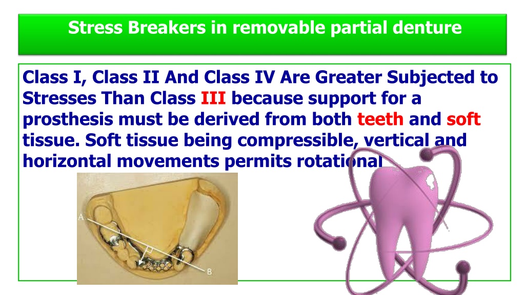
Stress Breakers in removable partial denture Class I, Class II And Class IV Are Greater Subjected to Stresses Than Class III because support for a prosthesis must be derived from both teeth and soft tissue. Soft tissue being compressible, vertical and horizontal movements permits rotational
Definition A stress breaker is a device that allows some movement between the denture base or its supporting framework and the direct retainers [whether they are intracoronal or extracoronal] Or may be defined are those elements of a partial denture which are interposed in a connector system in order to introduce a controlled and intentional degree of flexibility into the structure.
Stress equalizer is an integral part of a partial denture that will enable the operator to limit the movements between the clasps on the abutment teeth and the free end saddle to such a degree that the movement will be within the physiologic tolerance of the underlying tissues and equalize the stress between the abutment teeth and edentulous area.
Types of stresses created on the abutment teeth In general there are three types of stresses on the abutment teeth Vertical Lateral Oblique/anteroposterior Thus vertical stress results from a lack of distal tooth support. lateral stress results from a horizontal movement of the denture.
anteroposterior stress is a result of a combination of the first two. In all types of stress, the abutment becomes the fulcrum. To control these stresses and to distribute them between mucosa and the adjacent teeth requires a careful consideration of: 1] The condition of the teeth and mucosa 2] The impression techniques 3] The denture design 4] The distribution of stress between the mucosa and as many supporting teeth as possible
Aims of stress breaking To direct occlusal forces in the long axis of the abutment teeth. To prevent harmful loads being applied to the remaining natural teeth. To share load as evenly as possible between the natural teeth and saddle areas according to the ability of these different tissues to accept the loads. To ensure that part of the load applied to the saddle area is distributed as evenly as possible over the whole mucosal surface. To provide greater comfort to the patient.
Guidelines for stress breaker To decide whether to use a stress breaker or a rigid design Rule 1: If the teeth are strong and the ridge is poor flat, knife edged, or narrow- use a rigid design. Rule 2: If the teeth are weak e. g. , loss of supporting tissues so the mobility is plus or more and the ridge is strong, use a stress breaker.
Classification Stress breakers can be classified according to their mode of action: Type 1 Those utilizing a hinge or moveable joint. ( moveable joint between direct retainer and the denture base ) Type 2 Those utilizing flexible connection.
Type 1 Stress breakers These can be used in association with either precision attachments or clasp units as tooth bearing direct retainers. In this group fall the hinges, sleeves and cylinders, and ball and socket devices. The hinge is usually of a rigid design, the soft tissue absorbs a minimum of load adjacent to the hinge and a maximum of load toward the distal of the ridge. The base is permitted movement in a vertical plane only.
An example of this group are the various hinges, the Swiss made Dalbo attachment and the Crismani attachment. If the device works on a ball and socket principle, movement of the base is allowed in all planes and the tooth is relieved of all stress.
Type 2 Second group include those design having a flexible connection between the direct retainer and the denture base including wrought wire connectors, divided major connectors and other flexible devices for permitting movement of the distal extension base also included in this group are those using a movable joint between two major connectors. sleeve
Various forms which are commonly applied are: 1. Torsion bars/split bar major connectors Used in the design of a lower partial denture carrying bilateral free end saddles. Bars extend anteriorly from the clasp units on each side to join a lingual bar near the midline. Flexibility can be controlled by varying the cross section of the torsion bars, the method of construction (cast or wrought) and the material of construction (normally gold alloys or cobalt chromium alloys).
Disadvantages are In a torsion bar structure in that the double bar system is liable to trap food and cause irritation to the tongue. Some split connectors used as stress breakers have been known to pinch the underlying soft tissues or the tongue as they open and close under function.
2. Partial division of connectors This principle can be applied in both upper and lower dentures. For example, in a lower denture, a lingual plate may be partly divided by an antero posterior slot. The upper portion of the plate is attached to the retainer unit on the abutment tooth and the lower portion is attached to the saddle ,a degree of flexibility between the retainer unit and the saddle is so developed.
3. Mesial placement of occlusal rests This offers the simplest available approach to stress breaking. The degree of stress breaking achieved is though, much less than that available where more complex devices are employed. It may be used in the design of either upper or lower dentures. By positioning the rest of the clasp unit on the mesial instead of on the distal fossa of the abutment tooth and by using a minor connector to link the rest to a major connector some flexibility may be introduced into the clasp unit/saddle link.
Other types of stress breakers (12 gauge) chrome wire stress breaker The advantages : The extension base moves vertically immediately and the resiliency of the wire quickly returns the base to its original position The rigidity of the 12 gauge wire avoids overloading the mucosa. The mucosa is also more evenly loaded. It is easy to splint teeth with this design. The fabrication is relatively simple. Repairs are rarely needed.
Split palate stress breaker A stress breaker for a maxillary partial denture is often not necessary, has there is more alveolar ridge for support. In case of Kennedy class V, partial denture may be difficult to design, as the placement of a rest on the remaining weak anterior incisor is not considered desirable. The molar would be required to absorb most of the load of mastication on the left side. In such cases a split palate stress breaker was designed.
Advantages 1. Since the horizontal forces acting on the abutment teeth are minimized, the alveolar support of these teeth is preserved. 2. By careful choice of the type of flexible connector, it is possible to obtain a balance of stress between the abutment teeth and the residual ridge.
3 Intermittent pressure of the denture bases massages the mucosa, thus providing physiologic stimulation, which prevents bone resorption and eliminates the need for relining. 4 If relining is needed but not done, the abutment teeth are not damaged as quickly. 5 Splinting of weak teeth by the denture is made possible despite the movement of a distal extension base.
Disadvantages 1. The broken stress denture is usually more difficult to fabricate and therefore more costly. 2. Vertical and horizontal forces are concentrated on the residual ridge, resulting in increased ridge resorption. Many stress breakers designs are not well stabilized against horizontal forces. 3. If relining is not done when needed, excessive resorption of the residual ridge may result if exceed flexibility limits.
4. The effectiveness of indirect retainers is reduced or eliminated altogether. 5. The more complicated the prosthesis , the less it may be tolerated by the patient. Spaces between components are sometimes opened up in function, thus trapping food. 6. Flexible connectors may be bent and distorted by careless handling. Even a slightly distorted connector may bring more stress to bear on the abutment 7. Repair and maintenance of any stress breaker is difficult, costly, and frequently required.
Quadrilateral Configuration The quadrilateral configuration is indicated most often for Class III arches particularly when there is a modification space on the opposite side of the arch. A retentive clasp should be positioned on each abutment tooth adjacent to the edentulous spaces. This results in the denture being confined within the outline of the four clasps, and leverage on the denture is effectively neutralized.
For a Class III arch where no modification space exists, the goal should be to place one clasp as far posterior on the dentulous side as possible and one as far anterior as space and esthetics permit. This retains the quadrilateral concept and is the most effective way to control stress.
Tripod Configuration Tripod clasping is used primarily for Class II arches. If there is a modification space on the dentulous side, the teeth anterior and posterior to the space are clasped to bring about the tripod configuration. If a modification space is not present, one clasp on the dentulous side of the arch should be positioned as far posterior as possible, and the other, as far anterior.
Bilateral Configuration In case of bilateral distal extension group class 1 .the single retentive clasp arm on each side of the arch should be located near the centre of the dental arch or the denture bearing area. In the bilateral configuration the clasps exert little neutralizing effect on the leverage induced stresses generated by the denture base.