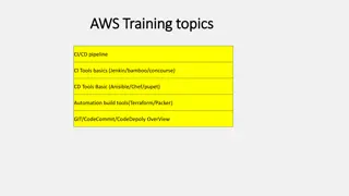
Overview of IEC 61850 Data Model for Substation Automation
This content provides an in-depth look into the IEC 61850 standard, focusing on logical devices, logical nodes, and their implementation in substation automation systems. It covers use cases, system specifications, model mapping, measurements examples, and hierarchical data modeling, offering valuable insights for professionals in the energy industry.

Download Presentation

Please find below an Image/Link to download the presentation.
The content on the website is provided AS IS for your information and personal use only. It may not be sold, licensed, or shared on other websites without obtaining consent from the author. Download presentation by click this link. If you encounter any issues during the download, it is possible that the publisher has removed the file from their server.
E N D
Presentation Transcript
IEC 61850 Model Examples Part 1: Logical Devices & Logical Nodes Tom Berry 02 August 2013
Introduction Usecase overview 61850 Data model Logical Devices & Logical Nodes Examples 2
Usecase summary Planning department issues a requirements document (maybe paper) Substation engineering produce a substation automation system using IEC61850 methods and tools Convert requirement to formal Substation Configuration Language => SSD System Specification Description Allocate specific IEDs and communications network => SCD System Configuration Description Export a copy of their model =>SED System Exchange Description EMS/DMS data maintenance team use a conversion tool Convert SED to some sort of CIM incremental update 3
Use case detail model mapping Which parts of the 61850 SSD , SCD or SED are useful in a CIM based system? The Substation Configuration Document defines Description of substation primary equipment & connectivity Similar but not the same as CIM Identification of Logical Nodes for each equipment Details of attributes for logical node types Standard: Vendor: Mandatory or Optional Extended 4
Measurements Example for a SEPAM S80 protection relay vs Logical Nodes Old IEC60870-5-103 or DNP3 344 Binary Inputs 68 Binary Outputs 128 Analogue Inputs 36 Counters >500, simple data points New IEC 61850 Around 80 Logical Nodes Includes Status, Measurands, configuration settings 70-80% standard data objects 20-30% vendor specific data objects fewer, more complex objects 5
61850 Data Model Logical Devices & Logical Nodes Definition in words Definition as a picture IED Relay example IEC61850-6 Annex D example substation one-line IEC61850-6 Annex D example distributed IEDs Draft 61850-7-500 Synchro-check and interlocking 6
IEC 61850 Hierarchical Data Model IED = Intelligent Electronic Device = a physical device = a server Each IED/physical device contains 1 or more instances of Logical Devices (LD) Each Logical Device contains many instances of Logical Nodes (LN) Each Logical Node is a standardised set of related Data Objects (DO) Data Objects have standard types = Common Data Classes (CDC) Common Data Classes define a set of Data Attributes Status information (digital values) Measurands (analogue values) Operation requests (if applicable) Settings (sometimes changed) Configuration (rarely changed) 7
IEC 61850 Hierarchical Data Model Physical Device Logical Device Logical Node Data Object Data Attribute Data Objects or Data Attributes standard but can be M Mandatory O Optional C Conditional F Forbidden (Ed 2.1) Example name SEPAM_IED/LD0/XCBR1.Pos.stVal 8
IED Example: Logical Nodes for a Relay Physical Device: SEPAM Logical Device: SEPAM S80 Station Bus GGIO GAPC Limit overflow HMI General Input / Output Automatic Process Control Switch position Subst. controller PTRC Trip Decision Trip Conditioning PTOC Start value Overcurrent Protection Process Bus RDRE gateway Disturbance recorder Measurement Unit XCBR RMS Measurements Circuit Breaker MMXU 9
IEC 61850-6 System Configuration example distributed physical devices 11
Draft 61850-7-500 Synchro-check and interlocking Remote switchgear positions Command from HMI (Remote) Busbar voltage XSWI.Pos.stVal TVTR.ValSv.instMag Station Bus XCBR.Pos.stVal Control IED CILO CSWI RSYN Process Bus Switch IED Breaker IED XSWI XSWI XCBR TVTR Physical I/O 12
Distribution Network Equipment Distribution Network Example Feeder loop operated with normal open point MV/LV Secondary Substation (Ring Main Unit) Contains 3 switch controllers Ring load break switch controller Main switch position & control, plus Earth switch Ring Switch other data points Current flow, voltage presence, fault passage indication IEC61850 Data Attribute Identification Summary of principles Ring Switch Data points identification Example 13
Distribution Network Example Primary Substation Primary Secondary 3 switches Recloser Spur Feeder Secondary 4 switches Normal Open Point MV/LV substations = Ring Main Units (RMU) European (3 wire) MV distribution network 14
MV/LV Secondary Substation Ring Main Unit (RMU) controller - logical devices RMU with 3 switches RTU SC1 Modelled as 1 main logical device and identical logical devices for the switch controllers SC2 SC3 15
Ring Switch Controller (part) - logical nodes Status modelled as two XSWI -Phase switch -Earth switch Each switch has 3 positions - Closed - Opened - Earthed (Grounded) CILO = Control interlock logic All 3 phases operated together CSWI = Switch control (pulse timing etc) SSWI = Switch Supervision CSWI1 SSWI1 PhaseXSWI1 Note: SSWI can report command failures regardless of source of command: local HMI, SCADA or automation CILO1 EarthXSWI1 16
Ring Switch other data points 3 Position switch with CTs and voltage sensor Other logical nodes (standard) MMXU Measurement Unit (proposed standard) SVPI Voltage Presence Indicator SFPI Fault Passage Indicator TCTR1 MMXU1 SFPI1 SVPI1 TVTR1 17
IEC61850 Data Attribute Identification Logical Device name Either product naming (vendor or configurable) Or functional naming (configurable) Logical Node name 3 parts LN Prefix Logical Node type LN Instance Optional usually fixed by vendor 61850 standard Fixed by vendor or configurable Data Object within LN 61850 standard or guidelines for extensions Data Attribute within CDC 61850 standard To be continued 18
Ring Switch Data points identification 3 Position switch Data points for each switch Generic Type Name (e.g. on web page) 61850 Common Data Class Logical Device LN Prefix Logical Node LN Ins Data Object Data Attribute Double bit digital input Double bit command Double bit digital input Single bit digital input SW1_status SW1_command SW1_locked SW1_command_failed DPC DPC DPC SPS SC_1 SC_1 SC_1 SC_1 / EmvPh / Emv / EmvEarth / Emv XSWI CSWI XSWI SSWI 1. Pos 1. Pos 1. Pos 1. OpTmAlm stVal stVal stVal stVal 19
For full details: IEC 61850 References IEC61850-5 lists Logical Node (LN) names IEC61850-6 defines the Substation Configuration Language And the profiles SCD, SSD, SED etc IEC61850-7-4 defines Logical Node (LN) classes IEC61850-7-3 defines Common Data Classes (CDC) IEC61850-7-2 defines Abstract communication service interface (ACSI) 20


")